Lamtec 662R2112 Mode D'emploi

Manuels Connexes pour Lamtec 662R2112

Sommaire des Matières pour Lamtec 662R2112
- Page 1 Betriebsanleitung elektr. 662R2112 Stellmotor Operatoring Instruction electr. actuator Mode d´emploi organes de manœvre electr. Drehmoment | torque | couple 30Nm Sensoren und Systeme für die Feuerungstechnik...
-
Page 2: Table Des Matières
Inhaltsverzeichnis Table of Content Table des matières Thema Kapitel Chapter | chapitre Theme | thème Allgemeine Hinweise General references | Indications générales Sicherheitshinweise Safety references | Indications de sécurité Einstellen der Endlagen Adjust the end positions | Ajuster les situations finales Elektrischer Anschluss Electrical connection | Raccordement électrique Maßzeichnung... -
Page 3: Allgemeine Hinweise
Indications générales Allgemeine Hinweise Gültigkeit dieser Anleitung: Diese Anleitung gilt für Stellmotor Fabrikat Lamtec Typ 662R2112 Diese Motoren sind ausschließlich zum Antrieb von Stellorganen von Feuerungsanlagen in Verbindung mit Lamtec Feuerungs und Verbund- Management Systemen Typ ETAMATIC, FMS oder VMS zugelassen, wenn Stellungsrückmeldung 1 mit Poti 5 kOhm ausgeführt ist. - Page 4 LAMTEC GmbH & Co KG will not accept liability for damages arising from failure to comply with the above instructions. The above instructions do not extend the warranty and liability conditions of the Conditions of Sale and Supply of LAMTEC GmbH &...
- Page 5 Protection et sécurité de l’appareil La loi de protection de sécurité de l’appareil stipule : Prendre en considération les indications de la notice d’utilisation seule les documentations No DLT 662R2112 sont valable Utiliser seulement l’appareil pour les applications décrites dans la manuel.
-
Page 6: Sicherheitshinweise
Sicherheitshinweise Safety references for Indications de sécurité für die Montage the assembly d'assemblages Sicherheitshinweise für die Montage Je nach dem, zu welchem Zeitpunkt und unter welchen Umgebungsbedingungen Sie den Stellantrieb montieren, sind spezielle Sicherheitsaspekte zu berücksichtigen. Die Montage und Inbetriebnahme des Antriebes darf nur durch •... - Page 7 Sicherheitshinweise Safety references for Indications de sécurité für die Montage the assembly d'assemblages Safety references for the assembly Depending upon that, at which time and under which site conditions you install the control drive, special safety aspects are to consider. •...
- Page 8 Sicherheitshinweise Safety references for Indications de sécurité für die Montage the assembly d'assemblages Indications de sécurité d'assemblages Selon cela, à quel moment et sous quelles conditions d'environnement vous installez l'organe de manœuvre, des aspects de sécurité spéciaux doivent être pris en considération . L'assemblage et le démarrage de la commande ne peuvent avoir •...
- Page 9 Sicherheitshinweise Safety references for Indications de sécurité für die Einstellungen the attitudes de réglages Sicherheitshinweise für die Einstellungen WARNUNG Stellen Sie sicher, dass durch die Inbetriebnahme bzw. durch die Testeinstellungen keine Gefahr für Mensch, Umwelt und Geräte/ Maschinen/Anlagen entstehen kann! WARNUNG Vergewissern Sie sich, dass die volle Bewegungsfreiheit der Stellantriebe gewährleistet ist und für das Personal keine...
- Page 10 Sicherheitshinweise Safety references for Indications de sécurité für die Einstellungen the attitudes de réglages Safety References for the Attitudes WARNING Guarantee that from start-up and/or from the test attitudes no danger for humans, environment and equipment/machine/plants can result!·· WARNING Make sure that the full freedom of movement of the control drives is ensured and exists for the personnel no squeezing danger! Establish to shut-off positions if necessary!·...
- Page 11 Sicherheitshinweise Safety references for Indications de sécurité für die Einstellungen the attitudes de réglages Indications de sécurité de réglages AVERTISSEMENT Garantissez que de démarrage et/ou de réglages d'essai, aucun danger pour homme, environnement et des installations d'appareil ne peut naître! AVERTISSEMENT Vous assurez que la liberté...
- Page 12 Gerätesicherheit Equipment Safety Sécurité de l'appareil Gerätesicherheit Die Stellantriebe sind nach anerkannten Regeln der Technik hergestellte • Qualitätsprodukte und haben das Herstellerwerk in sicherheitstechnisch einwandfreien Zustand verlassen! Zur Erhaltung des sicherheitstechnisch einwandfreien Zustandes ist es • zwingend notwendig, dass Monteur/Anwender sich strikt an die Herstellerangaben aus dieser Dokumentation halten und über eine entsprechende berufliche Qualifikation verfügen.
- Page 13 Gerätesicherheit Equipment Safety Sécurité de l'appareil Equipment Safety • The control drives are according to recognized rules of the technology manufactured quality products and the manufacturer in safety-relevant perfect condition left!· For the preservation of the safety-relevant perfect condition it is •...
- Page 14 Gerätesicherheit Equipment Safety Sécurité de l'appareil Sécurité de l'appareil • Les organes de manœuvre ont été des produits de qualité fabriqués après les règles reconnues de la technique et ont quitté le travail de fabricant dans un état à l'égard de règlements de sécurité parfait!· •...
-
Page 15: Einstellen Der Endlagen
Einstellen der Endlagen Adjust the End Positions Ajuster les situations finales Einstellen der Wegendschalter Die Wegendschalter mit Spitznocken 15° sind werkseitig ca. 90° oder 135° eingestellt. Die Feinjustierung erfolgt mit Schraubendreher an Schraube „F“. Schraube drehen, bis ein leichtes Klicken des Schalters zu hören ist. -
Page 16: Elektrischer Anschluss
Elektrischer Anschluss Electrical connection Raccordement électrique Elektrischer Anschluss Es sind die VDE- und EVU-Vorschriften beim Anklemmen der Regelantriebe zu beachten und sollten nur von einem zugelassenen Fachmann angeschlossen werden. Beachten Sie den in der Haube eingeklebten Anschlussplan und die außen am Stellantrieb angegebenen technischen Angaben. - Page 17 Elektrischer Anschluss Electrical connection Raccordement électrique Electrical Connection VDE and EVU specifications have to be observed when connecting our actuator motors. Connections are to be executed by an authorized specialist only. Please follow the connection diagram glued to the inside of the top as well as the technical information found on the outside of the actuating drives.
- Page 18 Elektrischer Anschluss Electrical connection Raccordement électrique Raccordement électrique Tenir compte des prescriptions VDE et EVU pour la connexion des mécanismes de commande. Le raccordement ne doit être effectué que par du personnel spécialisé autorisé. Veuillez tenir compte du schéma de raccordement collé à l’intérieur du capot ainsi que des informations techniques à...
- Page 19 Elektrischer Anschluss Electrical connection Raccordement électrique Kundenseitige Anschlüsse an Anschlussplatine MST5 mit elektrischer Handverstellung Connections Provided by the Customer at Connection Plate MST5 with electrically manual adjustment Raccordements chez le client à la plaque de raccordement MST5 avec réglage de l'allumage à main électrique Poti 2 (Option) Poti 1...
- Page 20 Elektrischer Anschluss Electrical connection Raccordement électrique Kundenseitige Anschlüsse an Anschlussplatine MST 5 Klemme1: An dieser Klemme wird der Schutzleiter angeschlossen. Dieser hat wie der Name schon sagt eine reine Schutzfunktion. Das heißt alle elektrisch leitenden Teile sind nach Anschluss des Schutzleiters mit dem Potential "Erde"...
- Page 21 Elektrischer Anschluss Electrical connection Raccordement électrique Zusatzschalter S3, potentialfrei Klemme 6, 15, 5: Klemme 6: Öffner von S3 Klemme 15: Wurzel von S3 Klemme 5: Schließer von S3 Klemme 16, 7, 17: Zusatzschalter S4, potentialfrei Klemme 16: Öffner von S4 Klemme 7: Wurzel von S4 Klemme 17: Schließer S4 Potentiometer 5kR (Poti 1)
- Page 22 Elektrischer Anschluss Electrical connection Raccordement électrique Connections provided by the customer at connection plate MST5 Holds the protective conductor witch is used -as indicated by the Terminal 1: name- for protective function only. All conductive parts are thereby connected to ground. Terminal 2: Holds the neutral conductor to provide for current flow, if necessary.
- Page 23 Elektrischer Anschluss Electrical connection Raccordement électrique Additional switch S3, floating Terminal 5, 15, 6 Terminal 6: nc-contact S3 (normally close) Terminal 15: root S3 Terminal 5: no-contact S3 (normally open) Additional switch S4, floating Terminal 16, 7, 17 Terminal 16: nc-contact S4 (normally close) Terminal 7: root S4 Terminal 17: no-contact S4 (normally open) Terminal...
- Page 24 Elektrischer Anschluss Electrical connection Raccordement électrique Raccordements chez le client à la plaque de raccordement MST5 Raccord du fil de protection a cette borne. Comme son nom Borne 1: l'indique, ce fil a une pure fonction de protection. Cela signifie que toutes les pièces a conduction électrique sont connectées au potentiel "terre"...
- Page 25 Elektrischer Anschluss Electrical connection Raccordement électrique Commutateur S3, sans potentiel Borne 5, 15, 6: Borne 6 : contact a ouverture de S3 Borne 15 : racine de S3 Borne 5 : contact a fermeture de S3 Commutateur S4, sans potentiel Borne 16, 7, 17: Borne 16 : contact a ouverture de S4 Borne 7 : Racine de S4...
- Page 26 Regelantrieb mit AC Synchronmotor Rückführung über Potentiometer und Stromsignal 4...20mA Bei Stellmotoren Fabrikat „LAMTEC“ mit elektronischer Regelung 4U20 mA ist das integrierte Signal 4U20 mA für die Stellungsrückmeldung, in Verbindung mit ETAMATIC/FMS/VMS, nicht als unabhängige und fehlersichere Rückführung im Sinne EN12067-2 verwendbar. In Verbindung mit ETAMATIC/FMS/VMS werden diese Motoren nur noch mit zusätzlicher Stellungsrückmeldung...
- Page 27 Elektrischer Anschluss Electrical connection Raccordement électrique Kundenseitige Anschlüsse an Anschlussplatine AB076 Regelantrieb mit AC Synchronmotor Klemme 8: An dieser Klemme wird er Neutralleiter angeschlossen. Dieser bewirkt, das bei Bedarf ein Stromfluss zustande kommen kann. An dieser Klemme wird der L-leiter angeschlossen Klemme 9: (Versorgungsspannung).
- Page 28 Elektrischer Anschluss Electrical connection Raccordement électrique Zusatzschalter S3, potentialfrei Klemme 14, 15, 16: Klemme 16: Öffner von S3 Klemme 14: Wurzel von S3 Klemme 15: Schließer von S3 Klemme 17, 18, 19: Zusatzschalter S4, potentialfrei Klemme 19: Öffner von S4 Klemme 17: Wurzel von S4 Klemme 18: Schließer S4 Rückführung Istwert Potentiometer 0...5kR...
- Page 29 Elektrischer Anschluss Electrical connection Raccordement électrique Connections provided by the customer at connection board AB076 actuator with AC Synchronous Motor Feedback via potentiometer and current signal 4…20mA At actuators with electronic controlling 4…20 mA the integrated signal 4…20 mA for the position feedback, in conjunction with ETAMATIC/FMS/VMS, can not be used as an independent and fail-safe position feedback in according to EN12067-2.
- Page 30 Elektrischer Anschluss Electrical connection Raccordement électrique Connections Provided by the Customer at Connection Board AB076 Actuator with AC Synchronous Motor Holds the neutral conductor to provide for current flow, if necessary. Terminal 8: L - 230V AC line voltage for supply Terminal 9: Holds the protective conductor witch is used -as indicated by the name- Terminal 10:...
- Page 31 Elektrischer Anschluss Electrical connection Raccordement électrique Additional switch S3, floating Terminal 14 , 15, 16 Terminal 16: nc-contact S3 (normally close) Terminal 14: root S3 Terminal 15: no-contact S3 (normally open) Additional switch S4, floating Terminal 17, 18, 19 Terminal 19: nc-contact S4 (normally close) Terminal 17: root S4 Terminal 18: no-contact S4 (normally open) Terminal 20...
- Page 32 AC moteur synchrone Retroaction via potentiometer et signal de courant 4…20mA Pour les servomoteurs de fabrications LAMTEC avec régulation électronique 4...20 mA, la recopie intégré 4...20 mA n'est pas un signal autocontrôlée au vue de la norme EN12067-2 et qui est nécessaire pour les appareils en liaison avec ETAMATIC/FMS/VMS.
- Page 33 Elektrischer Anschluss Electrical connection Raccordement électrique Raccordements chez le client à la plaque de raccordement AB076 Mécanisme de commande avec AC moteur synchrone Raccord du conducteur neutre a cette borne. Cela a pour effet qu'en cas de Borne 8 : besoin une conduction de courant est possible.
- Page 34 Elektrischer Anschluss Electrical connection Raccordement électrique Commutateur S3, sans potentiel Bornes: Borne 16 : contact a ouverture de S3 Borne 14 : racine de S3 14, 15, 16 Borne 15 : contact a fermeture de S3 Bornes: Commutateur S4, sans potentiel Borne 19 : contact a ouverture de S4 Borne 17 : racine de S4 17, 18, 19...
-
Page 35: Maßzeichnung
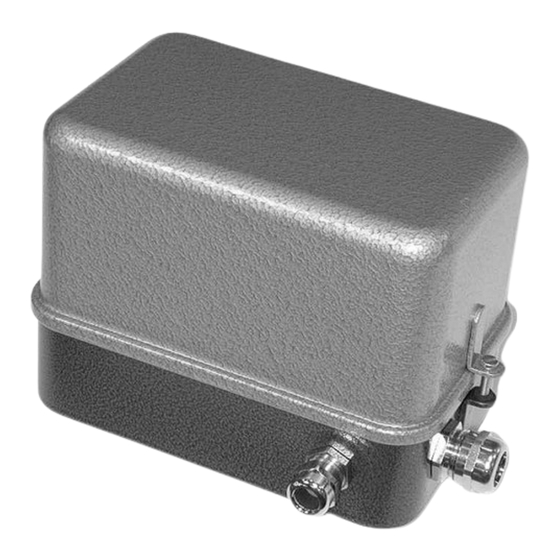
Maßzeichnung Dimensional Drawing Dessin Wellenendformen Forms of the end of the shaft Formes de fin de arbre WARNING / ATTENTION: WARNUNG / Bei Verbindung mit den Regelklappen Sicherheitshinweise beachten ! Consider safety references when connecting with the control damper. Par la connexion avec les clapets de réglage, veuillez prendre en considération les recommandations de sécurité. - Page 36 Maßzeichnung Dimensional Drawing Dessin Antrieb | Control drive | Organes de manœuvre 662R2112, IP54 Kap. 6...
- Page 37 Dessin Control drive Organes de manœuvre Antrieb | 662R2112, IP65 Hinweis Bei Montage im Freien empfehlen wir die Verwendung eines Regenschutzdaches ! When mounting outside, we recommend using a rain protection roof ! Lors du montage à l'extérieur, nous vous recommandons d'utiliser un toit housse de pluie !
-
Page 38: Technische Daten
Technische Daten Technical data Data technique Typ 662R2112 mit Drei-Punkt-Schritt-Ansteuerung “DPS”, IP54 Type 662R2112 with three-point-step-controlling “DPS”, IP54 Type 662R2112 avev regulation 3 pas-à-pas “DPS”, IP54 Antriebstyp 02-20 actuator type | type motor Typ Anschlussplatine MST 5 type connection plate... - Page 39 Technische Daten Technical data Data technique Zusätzliche Ohne Stellungsrückmeldung Without | sans Additional position feedback | oder / or / ou retroaction supplémentaire Potentiometer 0 - 5 K-Ohm, Fabrikat Novotechnik, TÜV zugelassen. potentiometer 0 - 5 k-Ohm, type Novotechnik, TÜV certified. potentiomètre 0 - 5 k-Ohm, marque Novotechnik, homologué...
- Page 40 Technische Daten Technical data Data technique Typ 662R2112 mit Drei-Punkt-Schritt-Ansteuerung “DPS”, IP65 Type 662R2112 with three-point-step-controlling “DPS”, IP65 Type 662R2112 avev regulation 3 pas-à-pas “DPS”, IP65 Antriebstyp 02-25 actuator type | type motor Typ Anschlussplatine MST 5 type connection plate...
- Page 41 Technische Daten Technical data Data technique Zusätzliche Ohne Stellungsrückmeldung Without | sans Additional position feedback | oder / or / ou retroaction supplémentaire Potentiometer 0 - 5 K-Ohm, Fabrikat Novotechnik, TÜV zugelassen. potentiometer 0 - 5 k-Ohm, type Novotechnik, TÜV certified. potentiomètre 0 - 5 k-Ohm, marque Novotechnik, homologué...
- Page 42 Technische Daten Technical data Data technique Typ 662R2112 mit elektronischer Regelung 4I20mA „REG“ Type 662R2112 with electronic controlling 4...20mA “REG” Type 662R2112 avec contrôle électronique 4...20mA « REG » Antriebstyp 02-25 actuator type | type motor Typ Anschlussplatine AB 076...
- Page 43 Technische Daten Technical data Data technique Adaption Lochkreis Ø 50 mm, 8 x 90°, M6 / ISO 5211 F07 adaption | adaptions circle of holes Ø 50 mm, 8 x 90°, M6 cercle de trous Ø 50 mm, 8 x90°, M6 Farbe Deckel Aluminium-Sandguss, Hammerschlag blau lackiert color cover | couleur...
-
Page 44: Ersatzteile
Ersatzteile Spare Parts Pièces de Rechange Ersatzteile / spare parts / pièces de rechange Poti NOVOTEC 0U5kOhm, 0...90°, incl. Ritzel / incl. gear / avec pignon Bestell-Nr. / order no. / no. d’ordre 660P7005 Poti NOVOTEC 0U5kOhm, 0...135, incl. Ritzel / incl. gear / avec pignon Bestell-Nr. - Page 45 Ersatzteile Spare Parts Pièces de Rechange Beim Austausch eines Potentiometers oder Endschalters ist folgendes zu beachten: Der Antrieb muss in den geschlossenen Zustand gefahren werden, d.h. • Position der Passfeder auf 12.00 Uhr Vor Öffnen der Haube muss die Versorgungsspannung abgeschaltet und vor •...
-
Page 46: Ec Declaration Of Confirmity | Déclaration De Conformité Ce
EC Declaration of Déclaration de conformité Konformitätserklärung Confirmity Kap. 8... - Page 47 EC Declaration of Déclaration de conformité Konformitätserklärung Confirmity EC Declaration of Conformity The control drives series 00-01-02-03 complies with the provisions of the following European Directives: 2004/108/EC directive of electromagnetic compatibility 2006/95/EC dirctive of low voltage EN60730 automatic electrical controls for household and similar use The conformity of the standards and regulations is verified by the CE sign.
- Page 48 LAMTEC Mess- und Regeltechnik LAMTEC Leipzig GmbH & Co KG Überreicht durch: für Feuerungen GmbH & Co KG Wiesenstr. 6 Portitzerstr. 69 D-69190 Walldorf D-04425 Taucha Telefon (+49) 06227 / 6052-0 Telefon +49 (341) 86329400 Telefax (+49) 06227 / 6052-57 Telefax +49 (341) 86329410 Internet: www.lamtec.de...