Aritech ATS1170 Instructions D'installation
Liens rapides
English
M
OUNTING
ATS1170 PCB can be mounted in any existing control panel housing which
supports the size B board.
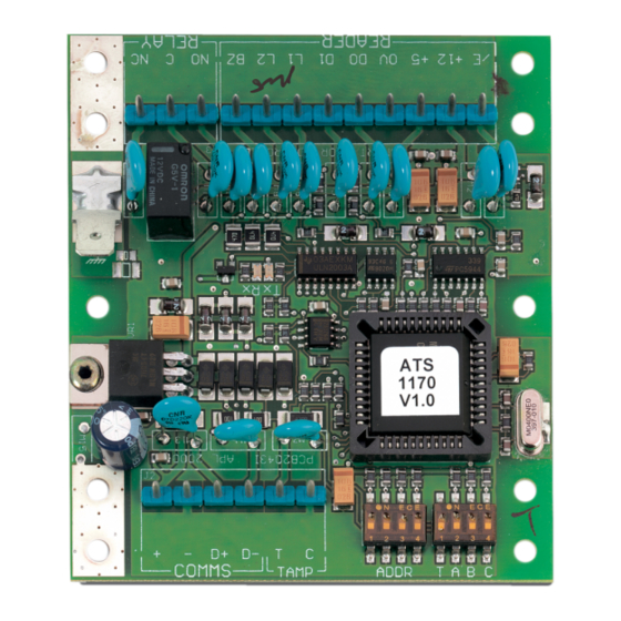
RAS DIP
SWITCH SETTINGS
Addressing : DIP switches 1 to 4 are used to identify the RAS number. See also
the Advisor control panel installation guide.
y y y y
DIP
(
)
SWITCHES
T
ON - the unit is the last physical device on the databus.(Term)
OFF - the unit is NOT the last physical device on the databus.
A
ON - enable the offline programming mode.
OFF - disable offline programming. Use this setting for standard operation.
B
ON - enable Financial Institution Magnetic swipe cards.
OFF - enable ATS format Magnetic swipe cards.
C
ON - Magnetic swipe card reader used.
OFF - Wiegand reader is used.
ATS
DATABUS CONNECTION
See Advisor Control Panel Installation guide.
C
J2 & J3
ONNECTIONS
J2
PWR 12 VDC supply input, COMMS Positive and negative data
connection of the databus.
J3
Unlock relay (NO/C/NC)
This relay is energised for the unlock period, i.e. when L1 or L2 is
flashing. See the Advisor control panel programming regarding this
arming station's output controller group (programming menu 3).
Français
M
ONTAGE
L'unité ATS1170 PCB peut être installée dans un coffret existant intégrant les
cartes au format B.
P
ARAMETRES DE DIPSWITCH
Adressage : Les dipswitch 1 à 4 correspondent aux numéros RAS. Consultez
également le guide d'installation de la centrale ATS pour plus d'informations.
y y y y
DIPSWITCH : (
)
T
ON – L'unité est le dernier dispositif physique présent sur le bus de
données. (Term)
OFF – L'unité N'EST PAS le dernier dispositif physique présent sur le bus
de données.
A
ON – Autorise le mode de programmation autonome.
OFF – Interdit le mode de programmation autonome. Utilisez ce paramètre
pour une utilisation standard.
B
ON – Active les cartes magnétiques spéciales Institution financière.
OFF Active les cartes magnétiques de la gamme ATS.
C
ON – Utilisation du lecteur à défilement.
OFF – Utilisation du lecteur Wiegand.
x
x
Address dipswitches
x x x x
(
)
(
) & E
SYSTEM OR LOCAL
ARTHING
RAS (x x x x )
y
y
LED
S
RX
LED flashes to indicate polling data is being received on the system
databus from the ATS control panel. If the LED does not flash the control
panel is not operational or the databus is faulty (usually cabling).
TX
LED flashes to indicate RAS is replying to polling from the ATS control
panel. If the RX LED flashes but the TX LED does not, the RAS is not
programmed to be polled in the control panel or is addressed incorrectly.
For details see the Advisor control panel installation guide.
R
EADER WIRING
/E
+ 5V
+ 1 2V
0V
D0
D1
L1
L2
BZ
C
ONNEXION DE BUS DE DONNEES
MISE A LA TERRE
Consultez le guide d'installation de la centrale ATS pour plus d'informations.
C
ONNEXIONS
J2 –
Entrée alimentation 12 Vcc et connexion du bus de données.
J3 –
Relais de déverrouillage (NO/C/NC)
Ce relais est alimenté pour toute la durée de déverrouillage, à savoir
lorsque le voyant L1 ou L2 clignote. Reportez-vous à la programmation
de la centrale ATS pour connaître le groupe de la carte de sortie de cette
station d'armement (menu de programmation 3).
V
OYANTS LUMINEUX
RX
Ce voyant clignote pour indiquer que des données de scrutation sont
reçues sur le bus de données du système en provenance de la centrale
ATS. Si ce voyant ne clignote pas, la centrale n'est pas opérationnelle
ou le bus de données est défectueux (généralement, il s'agit d'un
problème de câblage).
TX
Ce voyant clignote pour indiquer que la station d'armement répond à la
scrutation de la centrale ATS. Si ce voyant clignote, mais que le voyant
Model ATS1170
One Door RAS
J1
(Request to Exit) Input connection for door RTE button.
Shorting RTE to 0V will activate Request to Exit. (i.e. Request
to Exit button requires normally open contacts).
Power supply connection to the Reader (100 mA max. at 5 V fo
2 seconds and 75 mA constant).
Power supply connection to the Reader (100 mA max. at 12 V
for 2 seconds and 75 mA constant).
CAUTION! The + (positive) wire is connected to + 5 V or
+12 V depending on the type of reader used.
NEGATIVE Power Supply connection to Reader.
Data connection to Reader.
Data connection to Reader.
Open collector output to control Reader LED.
Open collector output to control Reader LED.
Open collector output to control Reader beeper if fitted.
Mini Contrôleur une porte
ATS (
SYSTEME OU LOCAL
J2
J3
ET
)
ET
1

Manuels Connexes pour Aritech ATS1170


Sommaire des Matières pour Aritech ATS1170
- Page 1 English One Door RAS OUNTING ATS1170 PCB can be mounted in any existing control panel housing which LED flashes to indicate polling data is being received on the system supports the size B board. databus from the ATS control panel. If the LED does not flash the control...
- Page 2 Italiano OFF – Utilizzo del lettore Wiegand. NSTALLAZIONE ’ Il C.S. dell’ATS1170 può essere montato in qualsiasi scatola per centrale in ONNESSIONE BUS DATI DELL DI SISTEMA O LOCALE grado di supportare le dimensioni della scheda B. E MESSA A TERRA...
- Page 3 Model ATS1170 J2 (RJ45) ABLAGGIO DEL LETTORE Il LED lampeggia per indicare che il bus dati del sistema riceve i dati di I colori qui citati fungono da esempio e possono variare a seconda del tipo e interrogazione dalla centrale ATS. Se il LED non lampeggia, la centrale della marca di cavo usato.
- Page 4 Model ATS1170 ECHNICAL SPECIFICATIONS PECIFICATIONS ECHNISCHE SPECIFICATIES PECIFICHE TECNICHE TECHNIQUES Power supply Alimentation Voedingsspanning Alimentazione 12 VDC Current consumption Consommation électrique Stroomverbruik Assorbimento without reader sans lecteur zonder kaartlezer senza lettore 45 mA max. Reader power output Sortie du lecteur...