Aritech ATS1210 Instructions D'installation
Liens rapides
English
M
OUNTING THE UNIT
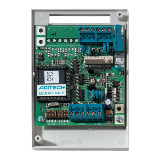
Mount the 4/8-zones Data Gathering Panel PCB in any existing ATS series
enclosure that supports the BB format.
C
J1
ONNECTIONS
COMMS
12 VDC power supply. It is recommended that where the distance
between an ATS1220 and the nearest device is more than 100
+
meters, a separate power supply be used.
-
COMMS
Positive and negative data connection of the system databus.
D+
Units can be up to 1.5 km from the 4-lift DGP or the ATS control
D-
panel, depending on the cable used. See the ATS control panel
installation guide for details.
T
TAMP
Connect the enclosure tamper switch across these terminals
C
(Tamper switch requires normally open contacts.)
L
INKS
Earth connection. Earth wires from all pieces of equipment must
be earthed at one system earth. For further detail see the ATS
control panel installation guide
DGP
DIPSWITCH SETTINGS
x
switches 1 to 4 are used to identify the DGP number.
ADDR
Dip
y
ABCT
T
Set switch T on if this device is the last device on the system
databus. For more details see the ATS control panel installation
guide.
A,C
Not in use
B
ON - ATS1811 8-way relay card or ATS1820 16-way open
collector card connected to J4.
OFF - no ATS1811 or ATS1820 connected to J4. Use this
setting also if an ATS1810 is connected to J4.
Français
M
'
ONTAGE DE L
UNITE
Installez la carte du circuit DGP à 4 zones dans un coffret de type ATS
existant prenant en charge le format BB.
C
J1
ONNEXIONS
COMMS
Alimentation 12 VCC. Si la distance entre une centrale
ATS1220 et le dispositif le plus proche est supérieure à
+
100 mètres, il est conseillé d'utiliser une alimentation distincte
-
pour les deux.
COMMS
Connexion de données positive et négative du bus de données
D+
du système. Les unités peuvent se trouver à une distance de
1,5 km de la centrale ATS ou du contrôleur à 4 ascenseurs,
D-
selon le câble utilisé. Pour plus d'informations, consultez
le guide d'installation de la centrale ATS.
.
TX
RX
x
y
LED'
S
RX
LED flashes to indicate polling data is being received on the system
databus from the ATS control panel. If the LED does not flash the control
panel is not operational or the databus is faulty (usually cabling).
TX
LED flashes to indicate the DGP is replying to polling from the ATS
control panel. If the RX LED flashes but the TX LED does not, it
indicates that the DGP is not programmed to be polled in the control
panel or that it is addressed incorrectly.
Z
ONE NUMBERING
A 4/8-zones DGP can have four or eight zones connected to it.
There are 16 zones allocated to every DGP address. Only zones 1 to 4 or 1 to
8 can be used when an ATS1210/1220 is allocated a DGP number. Zones not
available (5 - 16) or (8-16) should be programmed as type 0 (zone disabled)
in the Zone database.
Control panel
DGP1
DGP2
DGP3
DGP4
DGP5
DGP6
DGP7
Note 1: The ATS1210/1220 cannot be expanded to provide additional zones.
J4
OUTPUTS
J2
Each zones requires a 4k7 end-of-line resistor (1 or 2
depending on single or dual zone monitoring programmed in
ATS control panel).
J4
+12 VDC supply and open collector or data output for
Output
connection to ATS 1810, ATS 1811 and ATS 1820 output
cards via 10-way cable supplied with the output card. Up to
sixteen outputs are available with 8-way or 16-way open
collector cards (4-way and 8/16-way output cards cannot be
used together on the same DGP)
Autopro
Connecter le contact d'autoprotection du coffret sur ces deux
T
bornes (en principe, ce contact requiert des contacts ouverts).
C
C
ONNEXIONS ENTRÉES
J2
Chaque zone demande 1 ou 2 résistances de fin de la ligne
(4k7) en fonction de ce qui a été programmé dans la centrale.
J4
Alimentation +12 V et collecteur ouvert en sortie de données
Output
pour des connexions avec les cartes de sortie ATS1810,
ATS1811 et ATS1820 via un cable à 10 fils fourni avec la carte
de sortie. Seize sortie sont possibles avec 2 cartes 8 relais ou
1 carte 16 collecteurs ouverts.
Model ATS1210/1220
4/8-Zones DGP
1 – 16
DGP8
129 - 144
17 - 32
DGP9
145 - 160
33 - 48
DGP10
161 - 176
49 - 64
DGP11
177 - 192
65 - 80
DGP12
193 - 208
81 - 96
DGP13
209 - 224
97 - 112
DGP14
225 - 240
113 - 128
DGP15
241 - 256
DGP à 4/8 zones
/
SORTIES
1

Manuels Connexes pour Aritech ATS1210


Sommaire des Matières pour Aritech ATS1210
- Page 1 TAMP Connect the enclosure tamper switch across these terminals 8 can be used when an ATS1210/1220 is allocated a DGP number. Zones not (Tamper switch requires normally open contacts.) available (5 - 16) or (8-16) should be programmed as type 0 (zone disabled) in the Zone database.
- Page 2 ABCT Zet switch T aan indien dit apparaat het eerste of het laatste is op de Monteer de printplaat met de 8- of 4-ingangen DI (ATS1210 of ATS1220) in systeemdatabus. Zie voor meer details de installatiehandleiding van een behuizing van de Advisor Master-reeks waarin het BB-formaat past.
- Page 3 Model ATS1210/1220 4 oppure a 8 relè e in alternativa una scheda a 16 uscite open UMERAZIONE DELLE ZONE collector (le schede a 4 relè e 8 relè/16 uscite non possono essere Ad un concentratore ATS1220 possono essere collegate 4 zone. Ad ogni utilizzate insieme sullo stesso concentratore.
- Page 4 Model ATS1210/1220 ECHNICAL SPECIFICATIONS PECIFICATIONS ECHNISCHE SPECIFICATIES PECIFICHE TECNICHE TECHNIQUES Supply Voltage Tension d’alimentation Voedingsspanning Tensione di alimentazione 10,5 - 13,8 V DC. Current consumption Consommation électrique Stroomverbruik Assorbimento 53 mA max. Dimensions (H x W) (size B board). Dimensions (H x l) (carte de...