Table des Matières
Publicité
Les langues disponibles
Les langues disponibles
Liens rapides
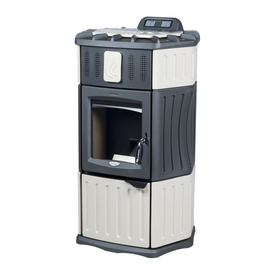
Apparecchi a combustibile solido con caldaia: pellets di legno
Residential space heating appliances with boiler fired by wood pellets
Appareil à combustible solide avec chaudière: pellets de bois
IT
LIBRETTO USO – MANUTENZIONE
GB
USING INSTRUCTIONS AND MAINTENANCE
FR
INSTRUCTIONS – USAGE – ENTRETIEN
Monella
Mod. 940 – 940/SA
1/112
Pag. 02
Pag. 39
Pag. 75
ErP
Cod. 90003204
Rev. 3
Publicité
Chapitres
Table des Matières

Manuels Connexes pour Lincar Monella

Sommaire des Matières pour Lincar Monella
- Page 1 Apparecchi a combustibile solido con caldaia: pellets di legno Residential space heating appliances with boiler fired by wood pellets Appareil à combustible solide avec chaudière: pellets de bois Monella Mod. 940 – 940/SA LIBRETTO USO – MANUTENZIONE Pag. 02 USING INSTRUCTIONS AND MAINTENANCE Pag.
-
Page 2: Table Des Matières
IT-GB-FR mod. 940-940/SA INDICE Sezione Pag. Installazione Misure collegamenti Distanze sicurezza Allacciamenti Dati tecnici Utilizzo Combustibile Pannello Comandi Regolazioni apparecchio Avviamento Segnalazioni Display Sicurezza Menu Pannello Comandi Dettaglio Menù Pulizia a carico dell’utilizzatore Manutenzione ordinaria Accessori Possibili inconvenienti e loro rimedio Segnalazioni Allarmi Esempi di collegamento impianto Condizioni di garanzia e richiesta intervento... -
Page 3: Installazione
IT-GB-FR mod. 940-940/SA INSTALLAZIONE PARTE DESTINATA ALL’INSTALLATORE Prescrizioni e norme • Leggere attentamente il contenuto del presente manuale, in quanto fornisce importanti indicazioni ed istruzioni riguardanti l’installazione, l’uso, la manutenzione e soprattutto la sicurezza del prodotto. • L’installazione, il collegamento elettrico ed idraulico, la verifica di funzionamento e la manutenzione vanno eseguite da Personale Qualificato, utilizzando sempre i dispositivi di sicurezza individuale e gli altri mezzi di protezione previsti per legge. -
Page 4: Misure Collegamenti
IT-GB-FR mod. 940-940/SA Avvertenze: La macchina è dotata di una valvola di sicurezza che interviene (se per qualsiasi motivo l’impianto termico supera la pressione di 3bar) scaricando il fluido contenuto nella caldaia. Al fine di evitare fastidiose uscite di acqua (non dovute a problemi), eventualmente generate da sovrapressioni dell’impianto di rete, è... -
Page 5: Distanze Sicurezza
IT-GB-FR mod. 940-940/SA Operazioni preliminari • Togliere delicatamente l’imballo. • Il materiale che compone l’imballo va riciclato mettendolo negli appositi contenitori o conferito al sito preposto nel comune di residenza. • Prima dell’installazione assicurasi dell’integrità dell’apparecchio, in caso di dubbio non utilizzarlo e rivolgersi al rivenditore. - Page 6 IT-GB-FR mod. 940-940/SA ALLACCIAMENTO ELETTRICO • La stufa viene fornita con un cavo H05RR-F 3x0.75 mm² di collegamento provvisto di spina europea. Il collegamento è di tipo “Y”, l’eventuale sostituzione deve essere effettuata da personale qualificato. Alimentazione 1N 230V AC 50Hz. Il cavo di collegamento deve essere disposto in modo tale da evitare qualsiasi contatto con superfici calde e/o taglienti.
- Page 7 IT-GB-FR mod. 940-940/SA • Disaerazione dell’impianto -Collegare l’apparecchio all’impianto di riscaldamento. -Riempire l’impianto e portarlo in pressione (es. 1,0 bar) 1- Sul display dell’apparecchio selezionare “Tarature Tecnico” ed inserire la password per accedere. 2- Selezionare “Test Uscite”. 3- Selezionare “Test Pompa”. 4- Mediante la pressione del pulsante 1 è...
- Page 8 IT-GB-FR mod. 940-940/SA Posizione selettore del circolatore in FUNZIONAMENTO Al termine dell’operazione di disareazione, il selettore del circolatore deve essere posizionato nella configurazione di massima (ruotare in senso orario a fine corsa), come da immagine della figura a lato, Primo funzionamento dell’impianto Durante la prima ora di funzionamento è...
- Page 9 IT-GB-FR mod. 940-940/SA CAMINO O CANNA FUMARIA Il camino o canna fumaria deve rispondere ai seguenti requisiti: - Essere a tenuta dei prodotti della combustione, impermeabile ed adeguatamente isolato e coibentato alla stregua delle condizioni di impiego (UNI 9615); - Essere realizzato in materiali adatti a resistere alle normali sollecitazioni meccaniche, al calore, all’azione dei prodotti della combustione e alle eventuali condense;...
- Page 10 IT-GB-FR mod. 940-940/SA COMIGNOLO Il comignolo deve rispondere ai seguenti requisiti: - Avere sezione interna equivalente a quella del camino; - Avere sezione utile di uscita non inferiore al doppio di quella interna del camino; - Essere costruito in modo da impedire la penetrazione nel camino di pioggia, neve, corpi estranei e in modo che anche in caso di venti di ogni direzione e inclinazione sia comunque assicurato lo scarico dei prodotti della combustione;...
- Page 11 IT-GB-FR mod. 940-940/SA Di seguito si riportano alcuni schemi consigliati a cui attenersi riguardanti lo scarico dei prodotti della combustione. Canna Fumaria Coibentata Canna Fumaria Coibentata Canna Fumaria in Muratura Isolata Canna Fumaria in Muratura Isolata 11/112...
- Page 12 IT-GB-FR mod. 940-940/SA Canna Fumaria Coibentata REALIZZAZIONE DELL’ALLACCIAMENTO ALLA CANNA FUMARIA • Eseguire il collegamento dell’apparecchio alla canna fumaria del camino esistente, assicurandosi che il tubo di uscita fumi non occupi la sezione libera della canna fumaria. Utilizzare esclusivamente tubi dotati di guarnizione di tenuta. •...
- Page 13 IT-GB-FR mod. 940-940/SA PRESA ARIA COMBUSTIONE DALL’AMBIENTE DI INSTALLAZIONE • L’apparecchio deve poter disporre dell’aria necessaria a garantirne il regolare funzionamento mediante prese d’aria esterna. • Le prese d’aria devono rispondere ai seguenti requisiti: Avere sezione libera totale minima di 200 cm²; Essere comunicanti direttamente con l’ambiente di installazione;...
-
Page 14: Dati Tecnici
IT-GB-FR mod. 940-940/SA Dati tecnici Monella Descrizione 940/SA Larghezza Profondità Altezza 1180 Peso apparecchio (senza acqua) Diametro scarico fumi Diametro aspirazione aria Potenza termica Max del focolare 19.9 Potenza termica utile Max (Nominale ) 18.6 Potenza utile Max all’acqua 14.4 Potenza utile Max all’ambiente*... - Page 15 IT-GB-FR mod. 940-940/SA Curve caratteristiche Circolatore 15/112...
-
Page 16: Utilizzo
IT-GB-FR mod. 940-940/SA UTILIZZO - PARTE DESTINATA ALL’UTILIZZATORE Avvertenze importanti • Leggere attentamente il contenuto della presente sezione, in quanto fornisce importanti indicazioni ed istruzioni riguardanti l’uso, la manutenzione e soprattutto la sicurezza del prodotto. • E’ di fondamentale importanza che il presente manuale, venga letto integralmente con la massima attenzione. - Page 17 IT-GB-FR mod. 940-940/SA Combustibile • Il combustibile da utilizzare è: PELLETS DI LEGNO DI BUONA QUALITA’ CARATTERISTICHE PELLETS PREGIATI Potere calorifico kWh/kg 4.8÷5.2 Densità kg/m Contenuto di acqua Max 8% del peso Percentuale ceneri Max 1% del peso Diametro Ø Lunghezza 20 ÷...
-
Page 18: Pannello Comandi
IT-GB-FR mod. 940-940/SA • Il carico del combustibile avviene dall’alto, dopo aver rimosso il coperchio superiore. A stufa funzionante utilizzare l’apposito guanto in dotazione in quanto le superfici possono raggiungere temperature elevate. Per evitare che il fuoco si spenga inavvertitamente a causa della mancanza di combustibile, si consiglia di controllare e mantenere costante un adeguato livello di pellets nel serbatoio di alimentazione. -
Page 19: Regolazioni Apparecchio
IT-GB-FR mod. 940-940/SA REGOLAZIONI APPARECCHIO (da eseguirsi integralmente prima di eseguire la 1° Accensione) REGOLAZIONE Temperatura Acqua per il Riscaldamento. L’apparecchio è dotato di un termostato posto sulla caldaia per il controllo della temperatura dell’acqua inviata all’impianto, questo termostato riduce progressivamente la potenza dell’apparecchio (modulazione) quando la temperatura dell’acqua in caldaia, raggiunge la temperatura impostata. -
Page 20: Avviamento
IT-GB-FR mod. 940-940/SA REGOLAZIONE Temperatura Ambiente Impostare la temperatura ambiente significa porre un limite al riscaldamento dell’apparecchio, qualora la temperatura dell’ambiente superi il valore impostato (es.20°) l’apparecchio ridurrà automaticamente la propria potenza portandosi al minimo per evitare spreco (potenza 1) di combustibile. -
Page 21: Segnalazioni Display
IT-GB-FR mod. 940-940/SA 1-ACCENDE 2-CARICA PELLETS (durata circa 2 min.) (durata max 18 / 20 min) (riscaldamento candeletta accensione) (caricamento del combustibile) 3-FUOCO PRESENTE Ultimato il ciclo di accensione l’apparecchio (durata 5 min.) (stabilizzazione bruciatore) funzionerà alla potenza impostata. L’apparecchio controlla continuamente la temperatura dell’ambiente e della caldaia, nel caso la potenza impostata fosse sufficiente a superare i valori impostati l’apparecchio ridurrà... -
Page 22: Sicurezza
IT-GB-FR mod. 940-940/SA L’apparecchio ha iniziato la fase di spegnimento e procede PULIZIA Spegnimento con lo smaltimento del combustibile presente nel cestello FINALE bruciatore. FUMI Temperatura fumi L’apparecchio ha rilevato una temperatura fumi elevata, elevata viene ridotto momentaneamente la potenza. MODULA Apparecchio in ALLARME... -
Page 23: Menu Pannello Comandi
IT-GB-FR mod. 940-940/SA -Controllo temperatura fumi. La temperatura dei fumi viene costantemente monitorata da una specifica sonda per controllare il regolare funzionamento dell’apparecchio, in caso la temperatura superi il livello di guardia , inizia un ciclo (il valore di guardia è impostato di fabbrica) di raffreddamento riducendo la potenza (FUMI MODULA), se la temperatura fumi continua a salire l’apparecchio inizia il ciclo di arresto e sul display sarà... - Page 24 IT-GB-FR mod. 940-940/SA MENU 02 (set crono) All’interno di questo Menu è possibile impostare i cicli di accensione/spegnimento automatici che si desidera utilizzare. Vi sono 3 diverse modalità che si possono utilizzare anche contemporaneamente, si raccomanda di prestare attenzione alla possibile sovrapposizione delle programmazioni.
-
Page 25: Dettaglio Menù
IT-GB-FR mod. 940-940/SA MENU 08 (correzz. pellet) Talvolta cambiando tipo di pellets, vista la varietà delle tipologie di pellets di legno presenti sul mercato possono verificarsi modifiche nella combustione dell’apparecchio. Un segnale evidente di una non efficiente combustione, è la presenza di eccessiva o scarsa quantità di pellets nel cestello bruciatore durante il normale funzionamento. - Page 26 IT-GB-FR mod. 940-940/SA PROGRAM GIORNO. Le programmazioni inserite in questa sezione si ripeteranno per tutti i giorni della settimana in ugual modo (max 2 cicli accendi/spegni) PROGRAM SETTIM. Con le programmazioni inserite in questa sezione è possibile eseguire accensioni/spegnimenti diversi nei giorni della settimana (max 4 cicli accendi/spegni). PROGRAM WEEK-END.
- Page 27 IT-GB-FR mod. 940-940/SA Attivare(on)/Disattivare(off) il MARTEDI PROG-2 on-oFF M-2-3-14 PROG-2 per il Martedì Attivare(on)/Disattivare(off) il MERCOLDI PROG-2 on-oFF M-2-3-15 PROG-2 per il Mercoledì Attivare(on)/Disattivare(off) il GIOVEDI PROG-2 on-oFF M-2-3-16 PROG-2 per il Giovedì Attivare(on)/Disattivare(off) il VENERDI PROG-2 on-oFF M-2-3-17 PROG-2 per il Venerdì Attivare(on)/Disattivare(off) il SABATO PROG-2 on-oFF...
- Page 28 IT-GB-FR mod. 940-940/SA STOP 1 WEEK-END Inserire orario 1 spegnimento 12:00 00:00-off M-2-4-03 START 2 WEEK-END Inserire orario 2 accensione 14:00 00:00-off M-2-4-04 STOP 2 WEEK-END Inserire orario 2 spegnimento 00:00-off M-2-4-05 Gli orari programmati si ripeteranno in tutti i week-end Per una corretta esecuzione dei programmi regolare con attenzione i dati del MENU 01.
-
Page 29: Pulizia A Carico Dell'utilizzatore
IT-GB-FR mod. 940-940/SA Menu 09 TARATURE TECNICO -(Riservato per TECNICI). Display Descrizione Esempio TARATURE TECNICO Menu riservato ai TECNICI CHIAVE ACCESSO Inserire il codice di accesso Questa sezione è riservata ai TECNICI per eseguire le eventuali regolazioni dell’apparecchio. Pulizia a carico dell’utilizzatore Per un corretto e funzionamento dell’apparecchio si rende necessario eseguire alcune piccole manutenzioni, eseguire le manutenzioni con apparecchio spento e freddo. -
Page 30: Manutenzione Ordinaria
IT-GB-FR mod. 940-940/SA Pulizia cassetto cenere. Aprire la porta inferiore, asportare il cassetto cenere (ruotare i due agganci laterali per sbloccare il cassetto), prelevare il cassetto cenere e svuotarlo prestando attenzione ad eventuali residui di combustibile ancora caldi, riposizionare il cassetto cenere nel proprio alloggiamento e richiudere. -
Page 31: Accessori
IT-GB-FR mod. 940-940/SA Accessori I seguenti attrezzi di servizio vengono forniti insieme alla stufa: Per le parti calde di manipolazione Per la pulizia dei condotti fumi (Attenzione, il particolare menzionato e riposto nella busta accessori, si ricorda che all’interno della porta inferiore è situato l’apposito supporto). Possibili inconvenienti e loro rimedio DIFETTO PROBABILE CAUSA... - Page 32 IT-GB-FR mod. 940-940/SA Segnalazioni di Allarme del Display Allarme Spiegazione Probabile Causa Rimedio Mancata alimentazione Verifica presenza pellets nel pellets. serbatoio Verifica funzionamento coclea. Non si è verificata Verifica collegamenti elettrici. l’accensione del combustibile in Rottura candeletta Sostituzione candeletta. fase di Mancata accensione.
- Page 33 IT-GB-FR mod. 940-940/SA Pressione errata Verificare la pressione dell’impianto termico. dell’impianto termico. (min. 0,5bar max. 2bar). Pressione troppo elevata Ridurre la pressione dell’impianto Rilevata pressione Press scaricando acqua. caldaia non Collegamenti elettrici Acqua corretta. interrotti. Verificare i collegamenti elettrici del pressostato. Rottura trasduttore di pressione Verificare/sostituire trasduttore di...
- Page 34 IT-GB-FR mod. 940-940/SA 34/112...
- Page 35 IT-GB-FR mod. 940-940/SA 35/112...
- Page 36 IT-GB-FR mod. 940-940/SA 36/112...
- Page 37 IT-GB-FR mod. 940-940/SA 37/112...
-
Page 38: Condizioni Di Garanzia E Richiesta Intervento
IT-GB-FR mod. 940-940/SA CONDIZIONI DI GARANZIA e RICHIESTA INTERVENTO • La Garanzia dell’apparecchio ha durata di anni due, così come previsto dalla Direttiva Europea 1999/44/CE sulla vendita dei beni di consumo. Il periodo è conteggiato a partire dalla data riportata sullo scontrino fiscale d’acquisto o sulla fattura o altro documento fiscale che comprovi l’avvenuto acquisto con data certa. - Page 39 IT-GB-FR mod. 940-940/SA INDEX Section Pag. Installation Connection measurements Security distances Connections Technical data Utilization Fuel Control panel Appliance regulation Starting Indications on Display Security Control panel menu Menu details Cleaning to be carried out by the User Ordinary maintenance Accessories Possible failures and cure Alarm indications...
-
Page 40: Installation
IT-GB-FR mod. 940-940/SA INSTALLATION SECTION DESTINATED TO THE INSTALLER Prescriptions and norms Read carefully the contents of this handbook, it contains important information and instructions for installation, use, maintenance and product safety. The installation, the electrical as well as the hydraulic connection, the working verification and the maintenance operations must be carried out by a qualified staff only, utilizing always the individual security devices and all other security features foreseen by local laws. - Page 41 IT-GB-FR mod. 940-940/SA Directions: The appliance is equipped with a security valve, which (in case that for any reason the pressure of the thermal plant is exceeding 3 bar) intervenes, discharging the fluid contained into the boiler. In order to avoid annoying outlets of water (not due to problems of the appliance) generated by overpressure of the hydraulic plant, we recommend to install a pressure reducing valve regulated at 1 bar, placed before the thermal plant charging cock.
-
Page 42: Security Distances
IT-GB-FR mod. 940-940/SA Preliminary operations Take away the packing Before installation, check the appliance integrity. In case of doubt, do not use the appliance and call the dealer. Packing materials is for recycle, getting it in the specify container Appliance positioning The installation room should have : A suitable floor for appliance weight. - Page 43 IT-GB-FR mod. 940-940/SA ELECTRICAL CONNECTION • The appliance is equipped with an electrical cable H05RR-F 3x0.75 mm² having an European plug. It is a type “Y” connection and therefore any replacement of the cable must be carried out by a qualified staff only. Feeding 1N 230V AC 50Hz. The electrical cable should be disposed in such a way to avoid any contact with hot and sharp parts.
- Page 44 IT-GB-FR mod. 940-940/SA Heating System Venting Phase -Connect the equipment with the heating installation. -Fill the heating installation and bring it on pressure (es. 1,0 bar) 1- On equipment’s display select “Tarature Tecnico” = “ Technical Setting” insert the password to enter. 2- Select “Test Uscite”...
- Page 45 IT-GB-FR mod. 940-940/SA Position selector circulator OPERATION ( In function When the venting phase is finished, the circulator selector has to be placed in the same position as in the picture. (Rotate clockwise at the stroke end). First functioning operation of heating installation During the first hour of functioning, we recommend to employ the equipment on power 1 ( minimum ) this to check the functioning of the entire heating installation to avoid that “particular”...
- Page 46 IT-GB-FR mod. 940-940/SA CHIMNEY OR FLUE The chimney or flue should have the following characteristics: Well sealed from combustion products, impermeable and completely insulated as normative condictions The flue has to be built with materials well suitable for normal mechanical stress, heat, action of combustion products and their condenses −...
- Page 47 IT-GB-FR mod. 940-940/SA CHIMNEY CAP The chimney cap should have the following characteristics: Internal section equivalent to the one of the chimney Exhaust section exit not lower than the double of the chimney internal one Built in a way to avoid rain, snow or external body entrance, to ensure the right exit of combustion products with any type of wind Positioned to guarantee the right fumes dispersion especially out of re-flux area.
- Page 48 IT-GB-FR mod. 940-940/SA Hereby some suggested schemes regarding the exhaust of the combustion products. Insulated Flue Insulated Flue Masonry insulated flue Masonry insulated flue 48/112...
- Page 49 IT-GB-FR mod. 940-940/SA Insulated Flue CONNECTION TO A FLUE • It’s advisable to read, follow and respect what indicated in the Section Installation. Connect the heating equipment to the flue / chimney verifying that the exhaust pipe does not enter into the free section of the flue. Employ only tubes supplied by seal gasket.
- Page 50 IT-GB-FR mod. 940-940/SA COMBUSTION AIR INTAKE DIRECTLY FROM THE INTALLATION ROOM • It’s advisable to read, follow and respect what indicated in the Section Installation. The equipment should have the necessary air for combustion, supplied by external air intake. The air intake should have the following characteristics : Total free section min 200 cm²;...
-
Page 51: Technical Data
IT-GB-FR mod. 940-940/SA Technical data Monella Description Width Depth Height 1180 Weight in ceramic (without water) Ø Diameter Exhaust Fumes Ø Diameter Air Suction Global Heat Input 19.9 Nominal Heat Output 18.6 Water Heat Output 14.4 Space Heat Output* Reduced Heat Input... - Page 52 IT-GB-FR mod. 940-940/SA Characteristic curves Circulator 52/112...
- Page 53 IT-GB-FR mod. 940-940/SA UTILIZING - SECTION DESTINATED TO THE USER Important warnings Read carefully the instructions of this section, which are very important for the use, the maintenance and the safety of the appliance. This handbook has to be read and studied in each part of it. Such a Lack can be considered an improper use of the equipment and therefore a not correct working of the appliance.
-
Page 54: Fuel
IT-GB-FR mod. 940-940/SA Fuel The fuel to be utilized is GOOD QUALITY WOOD PELLETS’ Calorific power kWh/kg 4,8÷5,2 Density kg/m Water contents Max 8% of weight Ash percentage Max 1% of weight Diameter Lenght 20 ÷ 30 Contents 100% untreated wood It is not allowed to use solid fuels as straw, mais, hazelnut, pinecone or others, different from the ones indicated in this handbook. - Page 55 IT-GB-FR mod. 940-940/SA CONTROL PANEL PUSH BUTTONS FUNCTIONS Button 1 (P1) - Pushed for one time you enter into the heating plant water temperature modification modality (use P1 and P2 to modify the value, P4 to exit). - Keeping it pushed, it indicates on the display the plant water temp. ,the pressure of the boiler and the loading time of fuel.
- Page 56 IT-GB-FR mod. 940-940/SA APPPLIANCE REGULATION (to be completely carried out before effecting the 1st Lighting) REGULATION of Heating water Temperature. The appliance is provided with a thermostat put on the boiler for the control of the water temperature sent to the plant, this thermostat reduces progressively the power of the appliance (modulation) whenever the temperature of the water inside the boiler has reached the selected temperature.
-
Page 57: Starting
IT-GB-FR mod. 940-940/SA REGULATION of the Room Temperature The setting of the room temperature means to put a limit to the heating process of the appliance, whenever the room temperature exceeds the selected value (i.e. 20°C) the appliance reduces automatically the power commuting on minimum (power 1) - Push on P2 - Regulate the temperature the buttons P1 and P2 - Terminate the regulation of the temperature of the water... -
Page 58: Indications On Display
IT-GB-FR mod. 940-940/SA 1-START (duration approx. 2min.) 2-LOAD PELLET (max. duration 18/20 min) (lighting element heating) (fuel loading) FLAME LIGHT (duration 5 min) Once the lighting phase has been completed, (burner stabilization) the appliance starts working normally During the working phase the appliance controls constantly the temperature of the room and of the boiler. - Page 59 IT-GB-FR mod. 940-940/SA SMOKE High fume Appliance noticed a too high fume temperature, the temperature power is at the moment reduced. MODULAT Appliance in Appliance noticed an anomaly, extinction cycle ALARM Alarm, start of starts and the display signals the type of problem. ACTIVATD extinction cycle PRODUCTION OF DOMESTIC WATER...
-
Page 60: Control Panel Menu
IT-GB-FR mod. 940-940/SA -Fume temperature control. The temperature of the exhaust fumes is constantly controlled by a specific feeler in order to control the regular working of the appliance, in case the temperature is exceeding the max. value (factory value setting) a stop cycle starts, while on the display appears “HOT EXHAUST”. - Page 61 IT-GB-FR mod. 940-940/SA MENU02 (crono setting) Within this Menu you can set up the automatic cycles of switching ON/OFF you desire to utilize. There are 3 different modalities you can utilize, even contemporaneously, but pay attention to not overlap the programmations. PROGRAM DAY.
- Page 62 IT-GB-FR mod. 940-940/SA MENU 08 (pellet correct) Sometimes, changing type of pellet, there are so many types of wood pellet on the market, the combustion of the appliance can be affected. A clear signal of an inefficient combustion is given by the quantity of pellets into the burner basket during the normal working phase: too much or too scarce.
- Page 63 IT-GB-FR mod. 940-940/SA PROGRAM DAY. The programmations inserted in this section will be repeated every day of the week in the same way (max 2 ON/OFF cycles) PROGRAM WEEK. With the programmations inserted in this section you can effect different ON/OFF during the days of the week (max 4 ON/OFF cycles) PROGRAM WEEK-END.
- Page 64 IT-GB-FR mod. 940-940/SA Activate(on) / Deactivate(off) MONDAY PROG-2 on-oFF M-2-3-13 PROG-2 for Monday Activate(on) / Deactivate(off) TUESDAY PROG-2 on-oFF M-2-3-14 PROG-2 for Tuesday Activate(on) / Deactivate(off) WEDNESDAY PROG-2 on-oFF M-2-3-15 PROG-2 for Wednesday Activate(on) / Deactivate(off) THURSDAY PROG-2 on-oFF M-2-3-16 PROG-1 for Thursday Activate(on) / Deactivate(off) FRIDAY PROG-2...
- Page 65 IT-GB-FR mod. 940-940/SA Activate(on) / Deactivate(off) to make operative or to exclude the programmings of the week START 1 WEEK-END Insert 1 starting hour 07:00 00:00-off M-2-4-02 STOP 1 WEEK-END Insert 1 extinction hour 12:00 00:00-off M-2-4-03 START 2 WEEK-END Insert 2 starting hour 14:00 00:00-off...
-
Page 66: Cleaning To Be Carried Out By The User
IT-GB-FR mod. 940-940/SA Menu 9 SETTINGS TECHNIC -(Reserved to TECHNICIANS). Display Description Example TECHNICAL SETTINGS Menu reserved to TECHNICIANS ACCESS KEY Insert access code This section is reserved to the TECHNICIANS and permits to effect working regulations on the appliance. Cleaning to be carried out by the User For the correct working of the appliance, it is necessary to carry out some short maintenance operations, these operations should be effected always with switched off appliance and in cold... -
Page 67: Ordinary Maintenance
IT-GB-FR mod. 940-940/SA Ashtray cleaning Open the lower door, take out the ashtray cover (to release the cover, turn the two lateral hooks), take the ashtray and empty it carefully, paying attention to possible hot combustion residuals, place the ashtray in its housing and closed the cover of the ashtray. DO NOT empty the ashes in inflammable containers, remember that into the ashes could be some embers, even after several hours from the extinction. -
Page 68: Accessories
IT-GB-FR mod. 940-940/SA Accessories The following accessories are supplied with the appliance : For warm parts To clean the fume ducts (Attention, this tool is placed into the accessories bag, we remind that at the inside part of the lower door there is a special support where you can store it). - Page 69 IT-GB-FR mod. 940-940/SA Alarm indications on display Alarm Explication Probable cause Cure No pellets feed Check if there is pellet into the container Check operating of screw feeder Check electrical wiring. In the starting phase the Lighting element broken Replace lighting element. lighting of lighting fuel failed or...
- Page 70 IT-GB-FR mod. 940-940/SA Wrong pressure of thermal Verify thermal plant pressure. plant. (min. 0,5bar max. 2bar). Too high pressure Reduce the pressure of the plant by Noticed draining water. Press wrong boiler Water Electrical connections Verify the electrical connections of pressure.
- Page 71 IT-GB-FR mod. 940-940/SA 71/112...
- Page 72 IT-GB-FR mod. 940-940/SA 72/112...
- Page 73 IT-GB-FR mod. 940-940/SA 73/112...
- Page 74 IT-GB-FR mod. 940-940/SA 74/112...
- Page 75 IT-GB-FR mod. 940-940/SA INDEX Pag. Section Installation Mesures Laçages Distances de sécurité Laçages Données Techniques Usage Combustible Panneau des commandes Régulations appareil Allumage – Mis en fonction Signalisation Display Sécurité Menu Panneau des commandes Détails Menù Nettoyage au soin de l’Utilisateur Entretien Ordinaire Accessoires Possibles inconvénients et leur résolutions...
-
Page 76: Installation
IT-GB-FR mod. 940-940/SA INSTALLATION PARTIE DESTINEE A L’INSTALLATEUR Normatives et prescriptions • Ce manuel est à lire avec attention car il fournit indications et informations très importants au sujet de l’installation, l’utilisation, l’entretien et surtout la sûreté de l’appareil. • L’installation, le laçage électrique et hydraulique, la vérification du fonctionnement et l’entretien sont à... - Page 77 IT-GB-FR mod. 940-940/SA ATTENTION : La machine est douée d’une soupape de sécurité qui intervient ( si l’installation thermique dépasse le 3bar de pression) et cause le déchargement du liquide contenu dans la chaudière. Pour éviter la sortie de l’eau causé par des surpressions de l’installation centrale, il est conseillé...
-
Page 78: Distances De Sécurité
IT-GB-FR mod. 940-940/SA Opérations Préliminaire • Enlever avec attention l’emballage. • Le matériel qui compose l’emballage est à recycler en le mettant dans les récipients spécifiques. • Avant d’installer l’appareil, il est convenable de vérifier son bon état, dans le cas contraire n’utiliser pas l’appareil et s’adresser au revendeur Positionnement de l’appareil •... -
Page 79: Laçages
IT-GB-FR mod. 940-940/SA LACAGE ELECTRIQUE • Le poêle est fournit avec cave H05RR-F 3x0.75 mm² de connexion avec épine européenne. Le laçage est du type « Y » et l’éventuelle maintenance ou substitution est à faire par personnel technique. Alimentation 1N 230V AC 50Hz. Il faut éviter que le cave de connexion soit en contacte avec surfaces chaudes et ou tranchant. - Page 80 IT-GB-FR mod. 940-940/SA • Désaération del l’installation - Raccorder l’appareil au système de chauffage. - Remplir l’installation et la mettre en pression (ex. 1,0 bar) 1- Sur le display de l’appareil sélectionner “Tarature Tecnico” = Set Technique et mettre le pass word pour rentre.
- Page 81 IT-GB-FR mod. 940-940/SA • Position du sélecteur du circulateur en FONCTIONNEMENT. A la fin de l’opération de désaération, le sélecteur du circulateur doit se trouver dans la position illustré à côté. (tourner en sens horaire jusqu’à la fin). Premier fonctionnement de l’installation Pendant la première heure de fonctionnement, il est convenable d’employer l’appareil à...
- Page 82 IT-GB-FR mod. 940-940/SA CHEMINEE OU CARNEAU Complètement hermétique pour les produits de combustion, imperméable, bien isolé et avec calorifugeage par apport aux conditions d’emploi. Les carneaux doivent être réalisés avec matériels adaptes aux normales contraintes mécaniques, à la chaleur, à l’action des produits de combustion et à leur condensation . Ils doivent avoir une structure verticale avec déviation de l’axe pas majeur de 45°...
- Page 83 IT-GB-FR mod. 940-940/SA PARTIE TERMINALE CONDUIT FUMEES La partie terminale du conduit des fumées doit avoir les caractéristiques suivantes : − Section équivalent à celle du cheminée − Section libre de sortie et pas inférieur au double de celle intérieure de la cheminée −...
- Page 84 IT-GB-FR mod. 940-940/SA En suite quelques exemples de réalisation de l’enlace pour la sortie des fumées de la combustion : Conduit fumées calorifugé Conduit fumées calorifugé Conduit fumées en maçonnerie calorifugé Conduit fumées en maçonnerie calorifugé 84/112...
- Page 85 IT-GB-FR mod. 940-940/SA Conduit fumées calorifugé REALISATION DU LACAGE AU CARNEAU • Exécuter le laçage de l’appareil au carneau de la cheminée existante, en s’assurant que le tube de sortie fumées n’occupe pas la section libre du carneau. • Employer exclusivement tuyaux doués de garniture •...
- Page 86 IT-GB-FR mod. 940-940/SA ALIMENTATION D’AIR DE COMBUSTION DANS LA PIECE D’INSTALLATION • L’appareil doit disposer de l’air nécessaire à garantir le fonctionnement régulier, à travers des prises d’air extérieures. • Les prises d’air doivent avoir les caractéristiques suivantes : Section totale Libre de 200 cm²; Communiquer directement avec la pièce d’installation ;...
-
Page 87: Données Techniques
IT-GB-FR mod. 940-940/SA Données Techniques Monella Description 940/SA Largeur Profondeur Hauteur 1180 Pois appareil Céramique (sans eau) Ø Décharge fumées Ø Aspiration air Puissance thermique Max du foyer 19.9 Puissance thermique utile Max (Nominale) 18.6 Puissance utile Max à l’eau 14.4... - Page 88 IT-GB-FR mod. 940-940/SA Courbes caractéristique circulatoire 88/112...
- Page 89 IT-GB-FR mod. 940-940/SA USAGE – PARTIE DESTINEE AU CLIENT Informations Importantes • Lire avec attention les instructions de la partie suivante car elle fournit des indications très importants concernant l’emploi, l’entretien, et surtout la sûreté de l’appareil. • Ce manuel doit être lu et étudié dans toutes ses parties car l’omission de ça sera considéré comme mauvais emploi de l’appareil donc un usage pas correct •...
-
Page 90: Combustible
IT-GB-FR mod. 940-940/SA Combustible • Le combustible à employer est : PELLETS DE BOIS DE BONNE QUALITE’ CARACTERISTIQUES DU PELLETS DE BONNE QUALITE Puissance calorifique 4.8÷5.2 kWh/Kg. Densité 650 kg/m³ Contenu d’eau Max 8% du pois Pourcentage de cendre Max 1% du pois Diamètre 6 mm Longueur... - Page 91 IT-GB-FR mod. 940-940/SA • Le chargement du combustible est à effectuer de l’haut, après l’enlèvement du couvercle supérieur. Pendant le fonctionnement du poêle, il faut employer le gant en dotation, car les surfaces puissent rejoindre températures très hautes. Il faut toujours contrôler et maintenir un bon niveau de Pellets au but d’éviter que le poêle s’éteint.
-
Page 92: Régulations Appareil
IT-GB-FR mod. 940-940/SA REGULATIONS APPAREIL (à faire complètement avant de faire le 1 er Allumage ) REGULATION Température Eau pour le Chauffage. L’appareil est doué d’un thermostat placé sur la chaudière pour le control ,de la température de l’eau, envoyé à l’installation, ce thermostat baisse progressivement la puissance de l’appareil(modulation) quand la température de l’eau dans la chaudière s’approche / rejoint la température programmée. - Page 93 IT-GB-FR mod. 940-940/SA REGULATION Température Ambiance Programmer la température de la pièce, signifie donner un limite au chauffage de l’appareil, dé que la température de la pièce passe le valeur programmé ( es.20°) l’appareil va réduire automatiquement sa propre puissance en se ponant à la puissance 1 pour éviter gaspillage de combustible.
-
Page 94: Signalisation Display
IT-GB-FR mod. 940-940/SA 1- ALLUMAGE 2-CHARGE PELLETS (durée env. 2 min.) (durée max 18/20 min) (chauffage bougie allumage) (chargement combustible) 3- FLAMME LUMIERE (durée 5 min.) Terminé le cycle d’allumage, l’appareil (stabilisation brûleur ) fonctionnera à la puissance programmée. L’appareil contrôle continuellement la température de l’ambiance et de la chaudière et dans le cas que la puissance programmée soit suffisante à... -
Page 95: Sécurité
IT-GB-FR mod. 940-940/SA L’appareil commence la phase d’éteignement ou il NETTOYAGE Eteignement commence à éliminer le combustible qui reste dans le panier FINALE brûleur FUMEES Température fumées L’appareil relève une température fumées élevées, la élevée puissance est redite pour l’instant. MODULA SIGNALE Appareil en alerte,... -
Page 96: Menu Panneau Des Commandes
IT-GB-FR mod. 940-940/SA - Contrôle température fumées. La température des fumées est toujours surveillé par une sonde spécifique pour contrôler le fonctionnement correct de l’appareil, si la température dépasse le niveau – garde ( ce valeur est programmé par le fabricant ), il commence un cycle d’arrêt en baissant la puissance (Fumées Module), si la température fumées continue à... - Page 97 IT-GB-FR mod. 940-940/SA MENU02 (set chrono) Avec ce menu, il est possible de programmer les cycles d’allumage / éteignement automatiques désirés. Il est possible d’employer trois différents modalités au même temps mais il faut faire attention aux possibles superpositions des programmations. PROGRAM JOUR.
- Page 98 IT-GB-FR mod. 940-940/SA MENU 08 (Correction pellet) Quelque fois, si l’appareil vient alimenté avec un autre type de pellet de bois, modifications dans la combustion de l’appareil peuvent se vérifier Le premier signale d’une mauvaise combustion est la présence d’une excessive ou baisse quantité de pellets dans le panier brûleur pendant le normal fonctionnement.
- Page 99 IT-GB-FR mod. 940-940/SA PROGRAM JOUR . Les programmations introduites dans cette section vont se répéter pour tous les jours de la semaine dans la même façon ( max 2 cycles allumage/éteignement) PROGRAM HEBDOMADAIRE . Avec les programmations introduites dans cette section, il et possible de réaliser allumage/éteignement différents pendant les jours de la semaine (max 4 cycles allumage / éteignement ).
- Page 100 IT-GB-FR mod. 940-940/SA Activer (on) / Désactiver (off) MARDI PROG-2 on-oFF M-2-3-14 le PROG-2 pour le Mardi Activer (on) / Désactiver (off) MERCREDI PROG-2 on-oFF M-2-3-15 le PROG-2 pour le Mercredi Activer (on) / Désactiver (off) JEUDI PROG-2 on-oFF M-2-3-16 le PROG-2 pour le Jeudi Activer (on) / Désactiver (off) VENDREDI PROG-2...
- Page 101 IT-GB-FR mod. 940-940/SA Introduire heure 1 STOP 1 WEEK-END 12:00 00:00-off M-2-4-03 éteignement START 2 WEEK-END Introduire heure 2 allumage 14:00 00:00-off M-2-4-04 Introduire heure 2 STOP 2 WEEK-END 00:00-off M-2-4-05 éteignement Les horaires programme se répèteront pendant tous les week-end. Pour une correcte exécution des programmes, régler avec attention les données du MENU 01 En choisissant oFF dans un programme de allumage/éteignement l’appareil n’exécutera pas le relatif commande, employer oFF seulement quand le poêle doit ou s’allumer ou s’éteindre...
-
Page 102: Nettoyage Au Soin De L'utilisateur
IT-GB-FR mod. 940-940/SA Menu 09 ARREGLAGES TECHNIQUES -(Reservé aux techniciens ). Display Description Example ARREGLAGES TECHNIQUES Menu réservé aux techniciens CLEF ACCES Introduire la clef d’accèss Cette section est reservée au techniciens pour réaliser les régulations de l’appareil Nettoyage au soin de l’Utilisateur Pour un fonctionnement correcte de l’appareil il est nécessaire de faire quelques opérations de entretien et maintenance. -
Page 103: Entretien Ordinaire
IT-GB-FR mod. 940-940/SA Nettoyage tiroir cendres. Ouvrir la porte inférieure, enlever le couvercle tiroir cendres (tourner les deux accrochages latérales pour débloquer le couvercle ) enlever le tiroir et le vider en faisant attention aux éventuels résidus chaudes de combustion, positionner de nouveau le tiroir des cendres dans sa propre siège et fermer le couvercle tiroir cendres. - Page 104 IT-GB-FR mod. 940-940/SA Outils de service Avec la poêle seront fourni ces outils de service, ils sont à utiliser pour . Toucher parties chaudes • Pour le nettoyage du conduits fumées (Attention ! ce outil se trouve dans l’enveloppe des outils, à l’intérieure de la porte inférieure se trouve son propre support ).
- Page 105 IT-GB-FR mod. 940-940/SA Signales de alerte du display Alerte Explication Possible Cause Solution Non – alimentation pellets. Vérifier présence pellets dans le réservoir. Vérifier fonctionnement vis sans fin. Vérifier laçages électriques. Non allumage du combustible en Rupture bougie allumage. Substitution bougie. phase de allumage Allumage ou l’appareil ne...
- Page 106 IT-GB-FR mod. 940-940/SA Pression de l’installation Vérifier la pression de l’installation thermique pas correcte. thermique ( min. 0,5bar max. 2bar). Pression trop élevée. Réduire le pression de l’installation Press Pression de la en faisant sorti eau. chaudière pas correcte Laçages électriques Vérifier les laçages électriques du coupés.
- Page 107 IT-GB-FR mod. 940-940/SA 107/112...
- Page 108 IT-GB-FR mod. 940-940/SA 108/112...
- Page 109 IT-GB-FR mod. 940-940/SA 109/112...
- Page 110 IT-GB-FR mod. 940-940/SA 110/112...
- Page 111 IT-GB-FR mod. 940-940/SA Note: 111/112...
- Page 112 IT-GB-FR mod. 940-940/SA Targhetta caratteristiche - Technical data plate Fiche Technique CORISIT S.R.L. Via Enrico Fermi 5, Z.I. Rame, 42046 Reggiolo (RE) Italy – P.Iva IT02628000354 www.corisit.com – info@corisit.com 112/112...