LEGRAND 261 93 Mode D'emploi
Masquer les pouces Voir aussi pour 261 93:
Table des Matières

Publicité

Les langues disponibles

Les langues disponibles

Liens rapides

B B o o î î t t i i e e r r
d d ' ' A A u u t t o o m m a a t t i i s s m m e e
Réf. 261 93 – Réf. 261 94
Octobre 08
Y1958C

Publicité

Chapitres

Table des Matières
loading

Sommaire des Matières pour LEGRAND 261 93

  • Page 1 B B o o î î t t i i e e r r d d ’ ’ A A u u t t o o m m a a t t i i s s m m e e Réf. 261 93 – Réf. 261 94 Octobre 08...
  • Page 3: Table Des Matières

    Table des matieres 1. Caractéristiques générales ..1.1 Versions ......1.2 Description .
  • Page 4: Caractéristiques Générales

    à l’application 1.5 Alimentation • 261 93 et 261 94 ont un double circuit d’ali- • Quand le boîtier est alimenté en CA et CC en mentation; ils peuvent être alimentés en CA et même temps, l’énergie est prélevé en CA CC en même temps, ou seulement en CA ou en...
  • Page 5: Description De La Façade

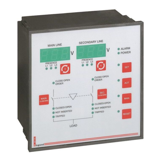
    2. Description de la façade 2.1 Touches de sélection • La façade du boîtier dispose de deux afficheurs à • Au centre la façade est représenté un synoptique diodes pour indiquer les tensions des deux qui indique l’état des appareils pour la connexion sources d’alimentation avec les deux touches cor- de la charge.
  • Page 6: Indicateurs À Diodes

    2.2 Sélections des mesures • En appuyant à plusieurs reprises sur la touche située • Au bout de 1 minute sans que la touche ait été sous chaque moniteur (A) et (B), il est possible de enfoncée, est rétablie la mesure par défaut qui visualiser successivement les différentes mesures de la peut être la première tension phase-phase ou la ligne correspondante.
  • Page 7 • Dans le tableau ci-dessus est indiquée la signification des différents témoins. Certains d’entre eux sont bicolores à savoir que leur signification est différente selon la couleur. Voyant Allumé Éteint Clignotant Un ou plusieurs alarmes actives ALARME Aucune alarme active (ROUGE) Boîtier alimentée (VERT) Absence alimentation...
  • Page 8: Modes De Fonctionnement

    3. Modes de fonctionnement • A l’aide des quatre touches SET / AUT / MAN • Si le voyant qui indique le mode de fonctionne- / RESET il est possible de sélectionner le mode ment sélectionné clignote, cela indique que l’ap- de fonctionnement voulu et indiqué...
  • Page 9: Mode Manuelle (Voyant Touche Man Rouge)

    3.2 Mode Manuel (voyant touche MAN rouge) • Le mode manuel permet à l’opérateur d’ouvrir/fer- boîtier ouvre initialement l’autre appareil, laisse mer électriquement les appareils à l’aide des s’écouler le temps d’inter-verrouillage puis ferme touches présentes sur la façade de l’appareil. l’appareil voulu.
  • Page 10: Applications

    4. Applications 4.1 Application Secteur-Groupe • Sur l’application secteur-groupe (U-G, configura- • Au retour de la ligne principale la charge est tion par défaut) la charge est en principe connec- retransférée et le groupe est maintenu en marche tée à la ligne principale. En présence d’une ano- sans charge pendant une durée préétablie de malie sur le secteur ou en cas de signal de trans- façon à...
  • Page 11: Commande Appareils

    5. Commande appareils • La commande de la motorisation des appareils est • Suite à une anomalie sur l’appareil provoquant assurée par deux relais distincts, l’un pour la fer- une alarme, les sorties de commande sont toutes meture et l’autre pour l’ouverture. deux ouvertes jusqu’à...
  • Page 12: Sans Feedback

    5.2 Sans feedback • Les voyants d’état de l’appareil restent éteints. • Les temps d’inter-verrouillage entre l’ouverture d’un appareil et la fermeture de l’autre est • Les alarmes de Timeout sont désactivées. décompté à partir de la commutation des sor- •...
  • Page 13: Contrôles De Tension

    P0.03). Ci-après sont indiquées les anomalies dont la gestion est assuré par le contrôle de tension. Les colonnes 261 93 et 261 94 indiquent la présence de la fonction sur les différents modèles du boîtier. Contrôle 261 93...
  • Page 14 • Chacune des anomalies a un temps de retard elle est de nouveau acceptable (ex. P2.02). La indépendant. L’anomalie doit avoir une durée inin- distance entre ces deux points définit l’hystérésis. terrompue supérieure au temps indiqué pour inva- Par exemple, on peut établir qu’en deçà de 80% lider le signal de présence tension.
  • Page 15: Programmation

    7. Programmation 7.1 Programmation des paramètres • Pour accéder à la programmation, appuyer sur les • Validation de la modification du paramètre avec touches H et E simultanément pendant 5 secondes la touche B d’affilée • Augmentation de la valeur du paramètre sélection- •...
  • Page 16: Tableau Des Menus

    7.2 Tableau des menus Menu Description Données nominales de l’installation Données générales Contrôle tension ligne principale Contrôle tension ligne secondaire Entrées programmables Sorties programmables Port de communication 7.3 Menu P0 - Données nominales Prog. Description Plage Par défaut P0.01 Tension nominale Ue 100 …...
  • Page 17: Menu P1 - Données Générales

    7.4 Menu P1 - Données générales Prog. Description Plage Par défaut U-G = Secteur-Groupe Type d’application P1.01 U-U = Secteur-Secteur Les paramètres OFF - Désactivé en évidence P1.02 Contrôle séquence phase 123 - Direct sont présents 321 - Inverse uniquement FEE - Avec feedback sur la version P1.03...
  • Page 18: Menu P2 - Contrôle Tension Ligne Principale

    7.5 Menu P2 - Contrôle tension ligne principale Prog. Description Plage Par défaut P2.01 Seuil tension minimum - décrochage 70…98% Ue 85% Ue P2.02 Seuil tension minimum - rétablissement 75…100% Ue 90% Ue Les paramètres P2.03 Retard seuil tension minimum 0.1 ….
  • Page 19: Menu P3 - Contrôle Tension Ligne Secondaire

    7.6 Menu P3* - Contrôle tension ligne secondaire Prog. Description Plage Par défaut P3.01 Seuil tension minimum - décrochage 70…98 % Ue 85 % Ue P3.02 Seuil tension minimum - rétablissement 75…100 % Ue 90 % Ue Les paramètres Retard seuil tension minimum 0.1 ….
  • Page 20: Menu P4 - Entrées Programmables

    7.7 Menu P4 - Entrées programmables Prog. Description Plage Par défaut P4.01 Fonction entrée - Programmable 1 Forçage sur ligne Voir liste secondaire “Fonctions entrées In.r programmables” P4.02 Fonction entrée - Programmable 2 Inhibition sur ligne principale Fonctions entrées programmables Fonction Description Notes...
  • Page 21: Menu P6 - Communication Série

    Fonctions sorties programmables Fonction Description Notes Sortie non utilisée Quand elle est fermée, le générateur doit être à l’arrêt. Validation mise en marche générateur Contact ouvert pour mettre en marche le générateur. S.GE Si la boîtier n’est pas alimentée, le générateur se met en marche Signal que le boîtier est en mode automatique et sans alarmes, Commutation transfert automatique prêt prêt à...
  • Page 22: Messages De Diagnostic

    8. Messages de diagnostic Sur les afficheurs peuvent être visualisés à différents moments les messages suivants: Code Description (Tirets) - La temporisation d’inter-verrouillage est active. - - - S’affichent du côté vers lequel la charge est en cours de transfert (Start) - Commande de mise en marche générateur (Cooling) - Le générateur est maintenu en marche pour effectuer le refroidissement (Test) - Si fixe, test off-load en cours, à...
  • Page 23: Alarmes

    9. Alarmes • Durant le fonctionnement du boîtier, peut se pré- • La sortie à relais Alarme générale est désactivée senter toute une série de situations anormales, les- en condition alarme, alors qu’elle est activée en quelles sont signalées de différentes manières. condition normale.
  • Page 24 Liste alarmes Description Code Voyant Cause MEM RESET alarme Se déclenche si le paramètre P0.06 n’est pas sur OFF et si la Tension batterie tension de batterie mesurée reste inférieure au seuil % programmé trop basse Les alarmes en sur P1.09 pendant la durée programmée sur P1.11 évidence sont Se déclenche si le paramètre P0.06 n’est pas sur OFF et si la présentes...
  • Page 25: Branchements

    10. Branchements Borne Fonction Borne Fonction Ouverture appareil ligne principale Entrée contact SD appareil ligne principale Commun commande ligne principale Entrée contact appareil débrochable ligne principale Fermeture appareil ligne principale Entrée contact CA appareil ligne secondaire Ouverture appareil ligne secondaire Entrée contact SD appareil ligne secondaire Commun commandes ligne secondaire Entrée contact appareil débrochable...
  • Page 26: Caractéristiques Techniques

    11. Caractéristiques techniques Alimentation auxiliaire Champ d’alimentation CC 9...70Vcc (Us=12-24-48Vcc) Champ d’alimentation CA 187…264Vca (Us=220…240Vca) Fréquence 45…65Hz Puissance absorbée max. 6VA (Us=240Vca) Puissance dissipée max. 4,8W (Us= 240Vca ou Us=48Vcc) Courant absorbé max. 420mA à 12Vcc; 200mA à 24Vcc; 100mA à 48Vcc Temps d’immunité...
  • Page 27 E E l l e e c c t t r r o o n n i i c c C C o o n n t t r r o o l l B B o o x x Item 261 93 – Item 261 94 October 08...
  • Page 29 Contents 1. General features ....1.1 Versions ......1.2 Description .
  • Page 30: General Features

    • Use the right wiring diagram for the application 1.5 Supply • 261 93 and 261 94 have a double power sup- • In presence of both power supplies, the energy is ply circuit, that means that they can operate with...
  • Page 31: Description Of The Front Panel

    2. Description of the front panel 2.1 Selection keys • The front panel of the electronic control box has • A mimic diagram is located at the center of the two LED displays showing the voltages of the two front panel; it shows the status of the circuit break- power sources with their correspondent keys –...
  • Page 32: Measurement Selection

    2.2 Measurement selection • When the key located under each display (A) and • After 1 minute without touching the key, the meas- (B) is pressed several times, it will be possible to view urement returns to the default measurement, which the various measurements of the line sequentially.
  • Page 33 • The following table describes the meaning of the various LEDs. Some of them are bicolor and have a different meaning according to the color. Flashing ALARM No alarm enabled One or more alarms enabled (RED) Device powered No power POWER SUPPLY (GREEN) OPEN/CLOSE...
  • Page 34: Operating Mode

    3. Operating mode • The four keys SET / AUT / MAN / RESET can • If the LED indicating the selected operating mode be used to select the required operating mode, flashes, it means that the device is communicating which will be indicated when the corresponding through the serial interface and that it could exe- red LED lights up.
  • Page 35: Manual Mode (Red Led Of Man Key)

    3.2 Manual mode (red MAN key LED) • The manual mode allows the operator to electrical- interlocking time and then it will close the required ly open/close the circuit breakers with the special circuit breaker. keys located at the front side of the device. •...
  • Page 36: Applications

    4. Applications 4.1 Utility-to-generator Application • In the Utility-to-generator application (U-G, default • When the main line returns, the load is transferred setup) the load is normally connected to the main again and the generator is kept in operation with line.
  • Page 37: Circuit Breakers Control

    5. Circuit breakers control • The circuit breakers control is carried out through • In case of an anomaly on the switch, hence caus- two separate relays, one for closing and one for ing an alarm, the control outputs will both be opening.
  • Page 38: Without Feedback

    5.2 Without feedback • The circuit breakers status LEDs remain off. • The changeover times between the opening of a switch and the closing of another start during • The timeout alarms are disabled. the commutation of the outputs and are steady •...
  • Page 39: Voltage Controls

    (via the P0.03 lowing menus. parameter). The following describes the anomalies monitored by the voltage control. Columns 261 93 and 261 94 point out the presence of the function within their unit models. Control 261 93 261 94...
  • Page 40 • Each anomaly has an independent delay time. tance between these two thresholds determines the The anomaly must last consecutively longer than hysteresis. For instance, it may be considered that the time specified for invalidating the voltage pres- when the nominal value is below 80%, the voltage ence signal.
  • Page 41: Programming

    7. Programming 7.1 Setting the parameters • Press the H and E keys together for 5 consecutive • Enable modification of the parameter with key B seconds to start programming • Increase the value of the selected parameter with • The flashing LED of the E key indicates that pro- key F gramming is in progress •...
  • Page 42: Table Of Menus

    7.2 Table of menus Menu Description System nominal data General Data Main line voltage control Secondary line voltage control Programmable inputs Programmable outputs Communication port 7.3 P0 menu - Nominal data Setup Description Range Default P0.01 Nominal voltage Ue 100 … 690 VAC 380 VAC Transformation ratio TV 1.00 …...
  • Page 43: P1 Menu - General Data

    7.4 P1 menu - General data Setup Description Range Default U-G = Utility-to-Generator Type of application P1.01 U-U = Utility-to-Utility OFF - Disabled The highlighted P1.02 Control of phase sequence 123 - Direct parameters are 321 - Opposite included only in version 261 94 FEE - With feedback P1.03...
  • Page 44: P2 Menu - Main Line Voltage Control

    7.5 P2 menu - Main line voltage control Setup Description Range Default P2.01 Minimum voltage threshold - release 70…98% Ue 85% Ue P2.02 Minimum voltage threshold - retrieval 75…100% Ue 90% Ue The highlighted P2.03 Minimum voltage threshold delay 0.1 …. 900 s 1.0 s parameters are included only in...
  • Page 45: P3 Menu - Secondary Line Voltage Control

    7.6 P3 menu - Secondary line voltage control Setup Description Range Default P3.01 Minimum voltage threshold - release 70…98 % Ue 85 % Ue P3.02 Minimum voltage threshold - retrieval 75…100 % Ue 90 % Ue The highlighted Minimum voltage threshold delay 0.1 ….
  • Page 46: P4 Menu - Programmable Inputs

    7.7 P4 menu - Programmable inputs Setup Description Range Default P4.01 Programmable input function 1 Forced changeover on secondary line See list ì P rogrammable input functions” In.r P4.02 Programmable input function 2 Inhibition return on main line Programmable input functions Function Description Notes...
  • Page 47: P6 Menu - Serial Communication

    Programmable output functions Function Description Notes Output not used When closed, the generator must be inactive. Consent to start up the generator Contact opens to start generator. S.GE If the unit is not powered, the generator starts Indicates unit automatically and without alarms, ready to Automatic transfer switch ready start operating Global alarm...
  • Page 48: Diagnostic Messages

    8. Diagnostic messages The following messages can be displayed, at different moments: Code Description (Dashes) - The interlocking time is in progress. - - - They are displayed from the side in which the load is being transferred (Start) - Indicates that the Start Generator command has been sent (Cooling) - Indicates that the generator is being left running for the cooling (Test) - When steady, it indicates that an off-load test - namely a power unit test with the voltage controls active - is currently in progress...
  • Page 49: Alarms

    9. Alarms • When the unit is running, it is possible to verify a • The Global alarm relay output is de-energized dur- number of abnormal situations which are signaled ing alarm conditions whereas it is energized under in different ways. normal conditions.
  • Page 50 Alarm list Description Code Causes RESET alarm This occurs if the P0.06 parameter is OFF and if the battery Battery voltage voltage measured remains lower than the threshold % set too low The highlighted with P1.09 for the time set with P1.11 alarm are This occurs if the P0.06 parameter is not OFF and if the included only in...
  • Page 51: Connections

    10. Connections Mors. Function Mors. Function Main line circuit breaker opening AL input of Main line circuit breaker Common main line commands DISCONNECTED input of Main line circuit breaker Main line circuit breaker closing AUX input of Secondary line circuit breaker Secondary line circuit breaker opening AL input of Secondary line circuit breaker Common secondary line commands...
  • Page 52: Technical Features

    11. Technical features Auxiliary power supply DC power supply operating limits 9...70VDC (Us=12-24-48VDC) AC power supply operating limits 187…264VAC (Us=220…240VAC) Frequency 45…65Hz Max. absorbed power 6VA (Us=240VAC) Max. dissipated power 4,8W (Us= 240VAC or Us=48VDC) Max. absorbed current 420mA to 12VDC; 200mA to 24VDC; 100mA to 48VDC Micro-breaking immunity time 50ms Voltage inputs...
  • Page 53 Schéma Wiring diagram Alimentation boitier et moteurs en 12-24-48Vdc LG1B Electronic Control Box and motors supply in 12-24-48Vdc Programmation des paramètres pour le schéma représenté sur la figure: Parameter setting for the wiring diagram in picture: Paramètre Programmation Parameter Setting P0.05 Principal Secondaire...
  • Page 54 Schéma Wiring diagram Alimentation boitier en 230Vac et 12Vdc et moteurs en 230Vac Electronic Control Box supply 230Vac and 12Vdc and motor supply in 230Vac Programmation des paramètres pour le schéma représenté sur la figure: Parameter setting for the wiring diagram in picture: Paramètre Programmation Parameter...
  • Page 55 Schéma Wiring diagram Relevé de tensions monophasées Single-phase voltage inputs Programmation des paramètres pour le schéma représenté sur la figure: Parameter setting for the wiring diagram in picture: Paramètre Programmation Parameter Setting P0.03 100 - 690 Vac 50/60 Hz Principal Secondaire Main 1A gG...
  • Page 56 Schéma Wiring diagram Relevé de tensions monophasées Single-phase voltage inputs Programmation des paramètres pour le schéma représenté sur la figure: Parameter setting for the wiring diagram in picture: Paramètre Programmation Parameter Setting P0.03 100 - 690 Vac 50/60 Hz Principal Secondaire Main PRINCIPAL...
  • Page 57 Schéma Wiring diagram Relevé de tensions biphasées Two-phase voltage inputs Programmation des paramètres pour le schéma représenté sur la figure: Parameter setting for the wiring diagram in picture: Paramètre Programmation Parameter Setting P0.03 100 - 690 Vac 50/60 Hz Principal Secondaire Main Sec.
  • Page 58 Schéma Wiring diagram Relevé de tensions biphasées Two-phase voltage inputs Programmation des paramètres pour le schéma représenté sur la figure: Parameter setting for the wiring diagram in picture: Paramètre Programmation Parameter Setting P0.03 100 - 690 Vac 50/60 Hz Secondaire Principal Main Sec.
  • Page 59 Schéma Wiring diagram Relevé de tensions triphasées Three-phase voltage inputs Programmation des paramètres pour le schéma représenté sur la figure: Parameter setting for the wiring diagram in picture: Paramètre Programmation Parameter Setting P0.03 100 - 690 Vac 50/60 Hz Principal Secondaire Main 1A gG...
  • Page 60 Schéma Wiring diagram Relevé de tensions triphasées Three-phase voltage inputs Programmation des paramètres pour le schéma représenté sur la figure: Parameter setting for the wiring diagram in picture: Paramètre Programmation Parameter Setting P0.03 100 - 690 Vac 50/60 Hz Principal Secondaire Main PRINCIPAL...
  • Page 61 Schéma Wiring diagram DPX 125/160 sans feedback LG10 DPX 125/160 without feedback Programmation des paramètres pour le schéma représenté sur la figure: Parameter setting for the wiring diagram in picture: Paramètre Programmation Parameter Setting P1.03 P1.04 P1.05 DPX 125: verrouillage mécanique non disponible DPX 125: mechanical interlock not available...
  • Page 62 Schéma Wiring diagram DPX 125/160 avec feedback LG11 DPX 125/160 with feedback Programmation des paramètres pour le schéma représenté sur la figure: Parameter setting for the wiring diagram in picture: Paramètre Programmation Parameter Setting P1.03 P1.05 DPX 125: verrouillage mécanique non disponible DPX 125: mechanical interlock not available DPX 125: contact de condition “non enclenché”...
  • Page 63 Schéma Wiring diagram DPX 125/160 avec EJP + feedback LG12 DPX 125/160 with EJP and feedback Programmation des paramètres pour le schéma représenté sur la figure: Parameter setting for the wiring diagram in picture: Paramètre Programmation Parameter Setting P1.03 P1.05 DPX 125: verrouillage mécanique non disponible DPX 125: mechanical interlock not available DPX 125: contact de condition “non enclenché”...
  • Page 64 Schéma Wiring diagram DPX 250/630 sans feedback LG13 DPX 250/630 without feedback Programmation des paramètres pour le schéma représenté sur la figure: Parameter setting for the wiring diagram in picture: Paramètre Programmation Parameter Setting P1.03 P1.04 P1.05...
  • Page 65 Schéma Wiring diagram DPX 250/630 avec EJP + feedback + declencheur EM LG15 DPX 250/630 with EJP + feedback + shunt trip Programmation des paramètres pour le schéma représenté sur la figure: Parameter setting for the wiring diagram in picture: Paramètre Programmation Parameter...
  • Page 66 Schéma Wiring diagram DPX 250/630 avec feedback + declencheur EM + arrêt d’urgence LG16 DPX 250/630 with feedback + shunt trip + emergency stop Programmation des paramètres pour le schéma représenté sur la figure: Parameter setting for the wiring diagram in picture: Paramètre Programmation Parameter...
  • Page 67 Schéma Wiring diagram DPX 1600 sans feedback LG17 DPX 1600 without feedback Programmation des paramètres pour le schéma représenté sur la figure: Parameter setting for the wiring diagram in picture: Paramètre Programmation Parameter Setting P1.03 P1.04 P1.05...
  • Page 68 Schéma Wiring diagram DPX 1600 avec feedback + declencheur EM + arrêt d’urgence LG19 DPX 1600 with feedback + shunt trip + emergency stop Programmation des paramètres pour le schéma représenté sur la figure: Parameter setting for the wiring diagram in picture: Paramètre Programmation Parameter...
  • Page 69 Schéma Wiring diagram DPX 1600 avec EJP + feedback LG20 DPX 1600 with EJP + feedback Programmation des paramètres pour le schéma représenté sur la figure: Parameter setting for the wiring diagram in picture: Paramètre Programmation Parameter Setting P1.03 P1.05...
  • Page 70 Schéma Wiring diagram DMX sans feedback LG21B DMX without feedback Programmation des paramètres pour le schéma représenté sur la figure: Parameter setting for the wiring diagram in picture: Paramètre Programmation Parameter Setting P1.03 P1.04 P1.05...
  • Page 71 Schéma Wiring diagram: DMX avec feedback + arrêt d’urgence LG22B DMX with feedback + emergency stop Programmation des paramètres pour le schéma représenté sur la figure: Parameter setting for the wiring diagram in picture: Paramètre Programmation Parameter Setting P1.03 P1.05...
  • Page 72 Schéma Wiring diagram DMX avec feedback LG23B DMX with feedback Programmation des paramètres pour le schéma représenté sur la figure: Parameter setting for the wiring diagram in picture: Paramètre Programmation Parameter Setting P1.03 P1.05...
  • Page 73 Schéma Wiring diagram DPX 125 1600 avec declencheur MT + arrêt d’urgence LG24B DPX 125 1600 with UVR and emergency stop Programmation des paramètres pour le schéma représenté sur la figure: Parameter setting for the wiring diagram in picture: Paramètre Programmation Parameter Setting...
  • Page 74 Programmation des paramètres Setting of parameters Valeur Valeur Setup Setup Value Value P0.01 P3.01 P0.02 P3.02 P0.03 P3.03 P0.04 P3.04 P0.05 P3.05 P1.01 P3.06 P1.02 P3.07 P1.03 P3.08 P1.04 P3.09 P1.05 P3.10 P1.06 P3.11 P1.07 P3.12 P1.08 P3.13 P1.09 P3.14 P1.10 P3.15 P1.11...

Ce manuel est également adapté pour:

261 94

Table des Matières