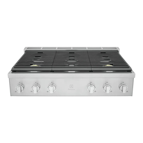
Publicité

Les langues disponibles

Les langues disponibles

Liens rapides

INSTALLATION INSTRUCTIONS
INSTALLATION AND SERVICE MUST BE PERFORMED BY A QUALIFIED
IMPORTANT: SAVE FOR LOCAL ELECTRICAL INSPECTOR'S USE.
READ AND SAVE THESE INSTRUCTIONS FOR FUTURE REFERENCE.
WARNING
FOR YOUR SAFETY: Do not store or use gasoline or other flammable vapors or
liquids near this or any other appliance.
Table of Contents
Product Dimensions ........................................ 4
Cabinet clearances.......................................... 4
Island installation............................................. 6
ance................................................................. 7
Electrical connection ....................................... 7
Gas safety ....................................................... 8
Gas connection ............................................... 9
If the instructions contained in this manual are not followed precisely, a fire
or explosion may result causing property damage, personal injury or loss of life.
FOR YOUR SAFETY:
• Do not store or use gasoline or other flammable vapors or liquids near this or any other appliance.
WHAT TO DO IF YOU SMELL GAS:
• Do not try to light any appliance.
• Do not touch electrical switches; do not use any phone in the building.
• Immediately call your gas supplier from a neighbor's phone. Follow the gas supplier's instructions.
• If you cannot reach your gas supplier, call the fire department.
INSTALLATION AND SERVICE MUST BE PERFORMED BY A QUALIFIED INSTALLER,
SERVICE COMPANY OR GAS SUPPLIER.
Note: For appliances installed in the State of Massachusetts, go to page 9.
Note: When operating at elevations higher than 2000 ft. above sea level, the appliance rating
should be reduced by 4 percent for each additional 1000 ft.
All rights reserved. Printed in Italy
36" GAS RANGETOP
INSTALLER.
Important Notes to the Installer
1. Read all instructions contained in these installa-
tion instructions before installing the range.
2. Remove all packing material from the oven and
the drawer compartments before connecting the
electrical and gas supplies to the range.
3. Observe all governing codes and ordinances. Be
sure to leave these instructions with the con-
sumer.
Important Note to the Customer
Keep these instructions with your owner's guide for
future reference.

Publicité

Table des Matières
loading

Sommaire des Matières pour Electrolux ECCG3672AS

  • Page 1: Table Des Matières

    INSTALLATION INSTRUCTIONS 36” GAS RANGETOP INSTALLATION AND SERVICE MUST BE PERFORMED BY A QUALIFIED INSTALLER. IMPORTANT: SAVE FOR LOCAL ELECTRICAL INSPECTOR'S USE. READ AND SAVE THESE INSTRUCTIONS FOR FUTURE REFERENCE. WARNING FOR YOUR SAFETY: Do not store or use gasoline or other flammable vapors or liquids near this or any other appliance.
  • Page 2: Important Safety Instructions

    36” GAS RANGETOP INSTALLATION INSTRUCTIONS IMPORTANT SAFETY INSTRUCTIONS This manual contains important safety symbols and insulating pad or sheet of ¼" (10,16cm) thick ply- instructions. Please pay attention to these symbols wood between the range and carpeting. and follow all instructions given. •...
  • Page 3 36” GAS RANGETOP INSTALLATION INSTRUCTIONS • In the event of an electrical power outage, the sur- Tip Over Hazard face burners can be lit manually. To light a surface WARNING burner, hold a lit match to the burner head and slowly turn the Surface Control knob to LITE.
  • Page 4: Product Dimensions

    36” GAS RANGETOP INSTALLATION INSTRUCTIONS Product Dimensions Cabinet clearances 912.4 mm 35 15/16" max: 688 mm max: 27 1/8" min: 681.5 mm min: 26 13/16” 190.5 mm 7 1/2" 914 mm 36” 46.5 mm 1 13/16" max: 619 mm max: 24 3/8” min: 612.5 mm min: 24 1/8”...
  • Page 5 36” GAS RANGETOP INSTALLATION INSTRUCTIONS Countertop cutout for gas and electric 2. Divide the measurement in half and draw the midline on the surface of the cabinet. connections 3. Measure 3” (76mm) from the front edge of the cabinet and draw a line perpendicular to the mid- line.
  • Page 6: Location Of The Gas And Electric Outlets

    36” GAS RANGETOP INSTALLATION INSTRUCTIONS Location of the gas and electric Island installation outlets If the appliance is installed as an island: 1. Unscrew the screws indicated. 2. Remove the spacers (A) and the screws (B). min: 24” min: 610 mm Keep a minimum clearance of 5 7/8"...
  • Page 7: Unpacking, Moving And Positioning The Appli- Ance

    36” GAS RANGETOP INSTALLATION INSTRUCTIONS Unpacking, moving and Electrical connection positioning the appliance Electrical shock hazard WARNING CAUTION This unit is designed as a cooking • This appliance is equipped appliance. For safety reasons, never use it for with a four-prong grounding warming the room or as a space heater.
  • Page 8: Gas Safety

    36” GAS RANGETOP INSTALLATION INSTRUCTIONS See the rating plate for technical specifications. The rating plate is visibly located at the bottom of the Electrical shock hazard WARNING appliance, towards the rear. • For personal safety, this appliance must be properly grounded.
  • Page 9: Gas Connection

    36” GAS RANGETOP INSTALLATION INSTRUCTIONS The maximum supply pressure of 14.0 inches water Install the pressure regulator (supplied with the unit) on the gas inlet. Install the gasket (supplied with the column (34.9 Millibars) must not exceed. unit) between the inlet and the regulator. Position WARNING State of California Proposi- the regulator so that the cap D is easily accessible.
  • Page 10 36” GAS RANGETOP INSTALLATION INSTRUCTIONS The technical data tables for the nozzles and burn- Connect the gas supply line to the unit pressure reg- ulator using a 1/2” flex gas line connector between ers are shown below the manual shut-off valve and the pressure regula- tor.
  • Page 11: Conversion To Propane Gas (Lpg)

    36” GAS RANGETOP INSTALLATION INSTRUCTIONS Testing for gas leaks Adjusting the minimum gas setting Since all cooktop burners are of the dual-flame type, WARNING NEVER use a flame to check for the minimum gas setting must be adjusted for both gas leaks.
  • Page 12 36” GAS RANGETOP INSTALLATION INSTRUCTIONS When checking if the regulator is working properly, 3. Invert the plastic regulator stem to achieve the the inlet pressure must be at least 1" greater than configuration “B” for Propane Gas and screw it in the operating (manifold) pressure above.
  • Page 13 36” GAS RANGETOP INSTALLATION INSTRUCTIONS 4. Remove the internal (8) and external (9) nozzles Refitting the burners and replace them with the LPG nozzles (see In order to be installed correctly, the shape of the "LPG nozzles table (Pressure in W.C.P.: 10”)"). burner skirt openings must match the shape of the openings in the burner base.
  • Page 15 INSTALLATION INSTRUCTIONS RACCORDEMENT DU GAZ 36’’ L’INSTALLATION ET L’ENTRETIEN DOIVENT ÊTRE EFFECTUÉS PAR UN INSTAL- LATEUR QUALIFIÉ. IMPORTANT : À CONSERVER POUR L’USAGE DES INSPECTEURS DES RÉSEAUX ÉLECTRIQUES LOCAL. LISEZ ET CONSERVEZ CES INSTRUCTIONS À TITRE DE RÉFÉRENCE ULTÉRIEURE. AVERTISSEMENT POUR VOTRE SÉCURITÉ...
  • Page 16: Consignes De Sécurité Importantes

    INSTALLATION INSTRUCTIONS RACCORDEMENT DU GAZ 36’’ CONSIGNES DE SÉCURITÉ IMPORTANTES Ce manuel contient des instructions et des symboles à moins de placer un tampon isolant ou une feuille de contreplaqué de ¼" (10,16cm) d'épaisseur de sécurité importants. Veuillez faire attention à ces entre la cuisinière et la moquette.
  • Page 17 INSTALLATION INSTRUCTIONS RACCORDEMENT DU GAZ 36’’ • N’utilisez jamais votre cuisinière pour réchauffer ou chauffer une pièce. L’utilisation prolongée de la Risque de AVERTISSEMENT basculement cuisinière sans une ventilation adéquate peut être dangereuse. • Un enfant ou une per- • N’entreposez pas ou n’utilisez pas d’essence ou sonne adulte pourrait d’autres vapeurs inflammables et de liquides à...
  • Page 18: Dimensions Du Produit

    INSTALLATION INSTRUCTIONS RACCORDEMENT DU GAZ 36’’ Il est de la responsabilité du propriétaire et de l'ins- Si vous retirez l’entretoise arrière, retirez également ses vis. L'épaisseur totale des entretoises et des tallateur de déterminer si des exigences supplémen- têtes de vis est de 0,256” (6,5 mm). taires et/ou des normes s'appliquent aux installations spécifiques.
  • Page 19 INSTALLATION INSTRUCTIONS RACCORDEMENT DU GAZ 36’’ • J = 36” / 914 mm minimum de dégagement entre « Dégagements des cabinets » - dégagement F). le dessus de la surface de cuisson et le fond du cabinet en bois ou en métal non protégé. •...
  • Page 20: Emplacement Des Prises De Gaz Et D'électricité

    INSTALLATION INSTRUCTIONS RACCORDEMENT DU GAZ 36’’ Emplacement des branchements élec- deux vis fournies. triques et de gaz de l'appareil X = Ligne d'alimentation en gaz REMARQUES : Y = Prise de terre • L'appareil doit reposer solidement dans la coupe et ne doit pas pouvoir se déplacer (par exemple Installation de l’îlot pendant le nettoyage).
  • Page 21: Déballage, Déplacement Et Positionnement De L'appareil

    INSTALLATION INSTRUCTIONS RACCORDEMENT DU GAZ 36’’ Déballage, déplacement et Branchement électrique positionnement de l’appareil Risque de choc AVERTISSEMENT électrique PRÉCAUTION Cet appareil a été conçu pour • Cet appareil est la cuisson. Pour des raisons de sécurité, ne l’utili- équipé d’une fiche à sez jamais pour chauffer la pièce ou comme chauf- quatre broches avec fage d'appoint.
  • Page 22: Sécurité Du Gaz

    INSTALLATION INSTRUCTIONS RACCORDEMENT DU GAZ 36’’ Voir la plaque signalétique pour les spécifications techniques. La plaque signalétique se trouve visible- Risque de choc AVERTISSEMENT ment au bas de l’appareil, vers l'arrière. électrique • Cet appareil doit être mis à terre pour votre sécurité...
  • Page 23: Raccordement Du Gaz

    INSTALLATION INSTRUCTIONS RACCORDEMENT DU GAZ 36’’ La pression d'alimentation maximale de 14,0 pouces Pour convertir l'appareil au gaz propane, voir « Conversion au gaz propane (GPL) ». La conversion de colonne d'eau (34,9 millibars) ne doit pas dépasser. doit être effectuée par un technicien ou un installateur qualifié.
  • Page 24 INSTALLATION INSTRUCTIONS RACCORDEMENT DU GAZ 36’’ Les tableaux des données techniques des injecteurs Raccordez la conduite d'alimentation en gaz au régulateur de pression de l'appareil à l'aide d'un et des brûleurs sont présentés ci-dessous connecteur de conduite de gaz flexible de 1/2” entre le robinet d'arrêt manuel et le régulateur de pres- sion.
  • Page 25: Conversion Au Gaz Propane (Gpl)

    INSTALLATION INSTRUCTIONS RACCORDEMENT DU GAZ 36’’ Test de fuites de gaz 1. Appuyez sur le bouton de commande du brûleur et allumez-le à la position minimale AVERTISSEMENT N’utilisez jamais de flamme pour vérifier des fuites de gaz. 2. Retirez le bouton de commande du brûleur, ainsi que le ressort conique et l’anneau du bouton.
  • Page 26 INSTALLATION INSTRUCTIONS RACCORDEMENT DU GAZ 36’’ Le régulateur de pression situé à l'entrée du collec- et vissez-la fermement. teur de la cuisinière doit rester dans la conduite d'ali- mentation. Utilisez un connecteur d'appareil métallique flexible ou un tuyau rigide pour connecter la cuisinière à l'alimen- tation en gaz.
  • Page 27 INSTALLATION INSTRUCTIONS RACCORDEMENT DU GAZ 36’’ Tableau des injecteurs de GPL (Pression en Remontage des brûleurs W.C.P. : 10”) »). Pour l’installer correctement, la forme des ouver- tures du dosseret du brûleur doit correspondre à la forme des ouvertures de la base du brûleur. PRÉCAUTION Cette procédure doit être exé- cutée pour chaque brûleur.
  • Page 29 INSTRUCCIONES DE MONTAJE PLANO DE COCCIÓN DE GAS DE 36” LAS OPERACIONES DE INSTALACIÓN Y SERVICIO TÉCNICO DEBEN SER LLE- VADAS A CABO POR UN INSTALADOR CUALIFICADO. IMPORTANTE: GUARDE ESTAS INSTRUCCIONES PARA USO DEL INSPECTOR ELÉCTRICO LOCAL. LEA Y GUARDE ESTAS INSTRUCCIONES PARA FUTURAS REFERENCIAS. ADVERTENCIA POR SU SEGURIDAD: No almacene o emplee gasolina u otros vapores o líquidos inflamables cerca de este o cualquier otro aparato.
  • Page 30: Instrucciones Importantes De Seguridad

    INSTRUCCIONES DE MONTAJE PLANO DE COCCIÓN DE GAS DE 36” INSTRUCCIONES IMPORTANTES DE SEGURIDAD Este manual contiene símbolos e instrucciones puede soportar una temperatura de al menos importantes con relación a la seguridad. Preste 90°F por encima de la temperatura ambiente sin atención a estos símbolos y siga las instrucciones encogerse, deformarse o decolorarse.
  • Page 31 INSTRUCCIONES DE MONTAJE PLANO DE COCCIÓN DE GAS DE 36” • No usar el horno como lugar de almacenamiento. Esto crea una situación potencialmente peligrosa. Peligro de vuelco ADVERTENCIA • No usar por ningún motivo la estufa para calentar el ambiente. Un uso prolongado de la estufa sin la •...
  • Page 32: Dimensiones Del Producto

    INSTRUCCIONES DE MONTAJE PLANO DE COCCIÓN DE GAS DE 36” La instalación debe realizarse en conformidad con Si retira los separadores traseros, retire también sus los códigos locales o, en ausencia de ellos, con el respectivos tornillos. El espesor total de los separado- Código Nacional de Gas Combustible, ANSI Z223.1/ res y de las cabezas de tornillo es de 0,256”...
  • Page 33 INSTRUCCIONES DE MONTAJE PLANO DE COCCIÓN DE GAS DE 36” • J = 36” / 914 mm distancia mínima entre la "Distancias del armario" distancia F). superficie de cocción y la base de un armario de madera o metal sin protección. •...
  • Page 34: Posición De Las Salidas Eléctricas Y De Gas

    INSTRUCCIONES DE MONTAJE PLANO DE COCCIÓN DE GAS DE 36” Posición de las conexiones de gas y dos tornillos suministrados. eléctricas del aparato X = Línea de suministro de gas NOTAS: Y = Salida de la puesta a tierra • El aparato debe estar bien colocado en el hueco y no debe poder moverse (por ejemplo, durante Instalación de isla la limpieza).
  • Page 35: Desembalaje, Desplazamiento Y Ubicación Del Aparato

    INSTRUCCIONES DE MONTAJE PLANO DE COCCIÓN DE GAS DE 36” Desembalaje, desplazamiento y Conexión eléctrica ubicación del aparato Peligro de descarga ADVERTENCIA eléctrica ATENCIÓN Esta unidad ha sido diseñada • El aparato cuenta con un como aparato de cocción. Por motivos de seguri- enchufe de puesta a tie- dad, nunca debe utilizarse para calentar ambien- rra con cuatro dientes...
  • Page 36: Seguridad Del Gas

    INSTRUCCIONES DE MONTAJE PLANO DE COCCIÓN DE GAS DE 36” Vea la placa de identificación para las especificacio- nes técnicas. La placa de identificación se encuen- Peligro de descarga ADVERTENCIA tra visiblemente colocada en la parte inferior del eléctrica aparato, hacia la parte trasera. •...
  • Page 37: Conexión Del Gas

    INSTRUCCIONES DE MONTAJE PLANO DE COCCIÓN DE GAS DE 36” La presión máxima de suministro no debe exceder de pano (GLP)". La conversión debe ser realizada por un técnico o instalador cualificado. Use una tubería 14,0 pulgadas de columna de agua (34,9 milibares). de gas flexible con una longitud de al menos 5 pies - ADVERTENCIA sobre la Propuesta 65...
  • Page 38 INSTRUCCIONES DE MONTAJE PLANO DE COCCIÓN DE GAS DE 36” A continuación se muestran las tablas con los datos Conecte la línea de suministro de gas al regulador de presión de la unidad mediante un conector de técnicos para las boquillas y los quemadores línea de gas flexible de 1/2"...
  • Page 39: Conversión A Gas Propano (Glp)

    INSTRUCCIONES DE MONTAJE PLANO DE COCCIÓN DE GAS DE 36” Comprobación de fugas de gas 1. Presione la perilla de control del quemador y enciéndala a la posición mínima ADVERTENCIA NUNCA utilice una llama 2. Retire la perilla de control del quemador, junto para comprobar la existencia de fugas de gas.
  • Page 40 INSTRUCCIONES DE MONTAJE PLANO DE COCCIÓN DE GAS DE 36” Utilice un conector flexible y metálico o una tubería 3. Invierta el vástago regulador de plástico para rígida para conectar la estufa al suministro de gas. conseguir la configuración “B” de gas propano y El conector debe tener un diámetro interior de 1/2"...
  • Page 41 INSTRUCCIONES DE MONTAJE PLANO DE COCCIÓN DE GAS DE 36” 4. Retire las boquillas internas (8) y externas (9) y Volver a montar los quemadores sustitúyalas con las boquillas de gas propano Para una instalación correcta, la forma de las aber- (vea "Tabla de las boquillas de gas propano turas del zócalo del quemador debe coincidir con la (Presión en c.d.a.: 10”)").
  • Page 44 914780092-A-112021...

Table des Matières