Eaton Z-LHASA Notice D'installation
Les langues disponibles
Les langues disponibles
Liens rapides
INSTRUCTIONS FOR INSTALLATION Shunt Trip Release Z-LHASA
1. Function and Description:
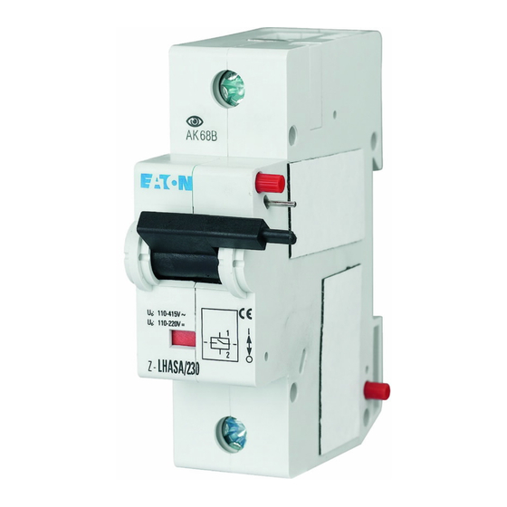
The shunt trip release type is a remote release based on the working current principle. The de-
vice for modular installation has been designed for installation on DIN support bars according to EN 50022. It is
1,5 MU (=27 mm) wide, has an optical switching position indicator (red/green) and can be mounted subsequently
on the left hand side onto any PLHT, miniature circuit breaker of up to 6 module units. Remote tripping is possible
within a wide voltage range. An auxiliary switch Z-LHK which can be connected additionally permits transmission
of a message that switchoff has occurred.
The sequence of installation as shown in the diagram must be observed, i.e. the shunt trip release must always
be installed to the left of the PLHT and the auxiliary switch Z-LHK on the right side.
When applying a voltage within the permitted range, the shunt trip release responds virtually without delay and
causes internal tripping of the PLHT mounted next to it. At the same time, it cuts the power supply to its own trip
coil and thus prevents thermal overload of the triipping device in case of continuous tripping commands. Conse-
quently, excessive length of the tripping pulse does not cause damage to the device. However, a minimum pulse
length is required for reliable functioning. The switching toggles of the Z-LHASA and PLHT are coupled mechani-
cally in such a way that when the PLHT is activated the toggle of the Z-LHASA is moved simultaneously. In case
the PLHT is switched off manually, the Z-LHASA trips mechanically even if no control voltage is present. In case
of electric tripping of the PLHT, the Z-LHASA is also activated internally by mechanical means and goes to the
OFF-position. If an external obstacle prevents the ASA switching toggle from moving to the OFF-position, the de-
vice may still trip internally like any PLHT independently of the toggle position.
2. Technical Data:
AC range
Responding limit
Operating voltage range
Max. current consumption at the moment of switching on
Duration of current flow at max. current consumption
DC range
Responding limit
Operating voltage range
Max. current consumption at the moment of switching on
Duration of current flow at max. current consumption
Minimum pulse duration
Internal resistance
Duty
Tripping time
Peak withstand voltage (1,2/50ms)
Service live operating cycles
Upper/lower terminals
Conductor cross section
1
Instruction Leaflet
Montageanweisung
Notice d'installation
Instrucciones de montaje
Istruzioni per il montaggio
Инструкция по монтажу
Montagehandleiding
Montagevejledning
Οδηγίες εγκατάστασης
Instruções de montagem
Monteringsanvisning
Asennusohje
Návod k montáži
Paigaldusjuhend
Szerelési utasítás
~
(V)
(V)
12 - 60
(A)
18 (at 24V)
(ms)
=
(V)
(V)
12 - 60
(A)
18 (at 24V)
(ms)
(ms)
(Ohm)
(%)
(ms)
(kV)
mm²
Montāžas instrukcija
Kullanma Talimatı
Montavimo instrukcija
Инструкција за монтажу
Instrukcja montażu
Intruksjonsblad
Navodila za montažo
Монтажна інструкція
تª ø¥u¤ة اL[ 
Návod na montáž
Монтажни инструкции
Instrucţiuni de montaj
Upute za montažu
24V
8
110 - 415
2 (at 230V)
4,5
11
110 - 230
2 (at 230V)
2
15
2,0
100
< 20
2
> 4000
lift / lift
2,5 - 50
GB
230V
70
4,5
90
4
10
130

Manuels Connexes pour Eaton Z-LHASA


Sommaire des Matières pour Eaton Z-LHASA
- Page 7 Les manettes de commande du Z-LHASA et du PLHT sont couplés mécanique- ment, de sorte que la manette du Z-LHASA est "entraînée" lors de la mise sous tension du PLHT. En cas de mise hors tension manuelle du PLHT, le Z-LHASA déclenche également (sur le plan mécanique) sans tension de commande.
- Page 8 5. Remarques : Le déclencheur à émission de tension Z-LHASA est compatible avec les bornes et les barres de raccordement de tous les appareils de connexion et de coupure. Les versions 24 V et 230 V possèdent une manette de commande de couleur grise (RAL 7035).