Table des Matières

Publicité

Les langues disponibles

Les langues disponibles

Liens rapides

BEDIENUNGSANLEITUNG
OPERATING INSTRUCTIONS
NOTICE D'UTILISATION
MCS 20
Kabelgebundenes Konferenzsystem
Wired Conference System
Système de conférence à fil

Publicité

Table des Matières
loading

Sommaire des Matières pour Beyerdynamic MCS 20

  • Page 1 BEDIENUNGSANLEITUNG OPERATING INSTRUCTIONS NOTICE D’UTILISATION MCS 20 Kabelgebundenes Konferenzsystem Wired Conference System Système de conférence à fil...
  • Page 3: Table Des Matières

    Netzgerät MCS 20........
  • Page 4: Einführung

    MCS 20 – Netzgerät Sie haben sich für das kabelgebundene Konferenzsystem MCS 20 von beyerdynamic entschieden. Wir danken für Ihr Vertrauen. Nehmen Sie sich bitte einige Minuten Zeit und lesen Sie diese Bedienungsanleitung vor Inbetriebnahme aufmerksam durch. Folgende Komponenten gehören zur Grundausstattung eines Systems: •...
  • Page 5 • Setzen Sie das Gerät nicht ein, wenn der Netzstecker beschädigt ist. • Wenn Sie defektes oder ungeeignetes Zubehör anschließen, kann das Gerät beschädigt werden. Verwenden Sie daher nur die von beyerdynamic lieferbaren oder empfohlenen Anschlusskabel. Verwenden Sie selbstkonfektionierte Kabel, erlischt Ihr Garantieanspruch.
  • Page 6: Bedienelemente

    MCS 20 steckt. Im Sicherungshalter befindet sich die 3,15 AT Kurzschlusssicherung. Renk-Buchsen • Das Netzgerät MCS 20 ist mit Renk-Buchsen ausgestattet zum Anschluss von weiteren Netzgeräten MCS 20 sowie Sprechstellen . An den weiteren Netzgeräten können Sie jeweils eigene Sprechstellen anschließen.
  • Page 7: Verkabelung

    (HE) frei für eine ausreichende Wärmeabfuhr. Der Raum hinter den Geräten darf nicht abgeschlossen sein. Wichtig: Wenn Sie das Netzgerät MCS 20 in ein Rack einbauen, achten Sie bitte darauf, dass das Rack geerdet ist (mit dem Schutzleiter der Elektroinstallation verbunden).
  • Page 8: Sprechstellen

    Verbindungen können zu Störungen führen. Haftungsausschluss • Die Firma beyerdynamic GmbH & Co. KG übernimmt keine Haftung für Schäden am Produkt oder Verletzungen von Personen aufgrund unachtsamer, unsachgemäßer, falscher oder nicht dem vom Hersteller angegebenen Zweck entsprechender Verwendung des Produkts.
  • Page 9: Bedienung Delegiertensprechstelle Mcs 221

    MCS 20 – Sprechstelle MCS 221 Ansicht von unten Ansicht von oben Konfigurationsschalter (DIP-Schalter) Schwanenhalsmikrofon mit Leuchtring Mikrofontaste mit LED Lautsprecher 3.2.1 Bedienung Delegiertensprechstelle MCS 221 • Zum Sprechen muss das Mikrofon der Delegiertensprechstelle MCS 221 aktiviert sein. Bei einem eingeschalteten Mikrofon leuchtet der Leuchtring am Schwanenhals sowie die LED in der Mikrofontaste .
  • Page 10: Konfigurationsschalter

    MCS 20 – Sprechstelle MCS 221 3.2.2 Konfigurationsschalter • Auf der Unterseite der Delegiertensprechstellen befinden sich Konfigurationsschalter, die einer Sprechstelle je nach Stellung ON bzw. OFF, die in der Tabelle aufgelisteten Funktionen zuweisen. Zum Programmieren der von den Standardfunktionen abweichenden Funktionen der Präsidentensprechstelle MCS 223 siehe Kapitel 3.3.8 „Programmiermodus“...
  • Page 11 MCS 20 – Sprechstelle MCS 221 2 OFF – Sprechstelle wird für das Limit im VOICE-Betrieb nicht mitgezählt Dieser Schalter gilt nur für die Delegiertensprechstelle MCS 221. 3 OFF – Limit gilt nicht für diese Sprechstelle Der Redner kann diese Sprechstelle auch dann einschalten bzw. anmelden, wenn jeweils das Limit bereits erreicht ist.
  • Page 12: Bedienelemente Präsidentensprechstelle Mcs 223

    MCS 20 – Sprechstelle MCS 223 3.3 Bedienelemente Präsidentensprechstelle MCS 223 Ansicht von hinten Ansicht von oben Konferenzbuchse; Anschluss von/zur nächsten Sprechstelle bzw. Anschluss an Netzgerät Kopfhöreranschluss, Klinke 3,5 mm Konferenzbuchse; Anschluss von/zur nächsten Sprechstelle bzw. Anschluss an Netzgerät Schwanenhalsmikrofon mit Leuchtring...
  • Page 13: Betriebsarten

    MCS 20 – Sprechstelle MCS 223 – „Limit“-Tasten zum Einstellen der zugelassenen Anzahl eingeschalteter bzw. angemeldeter Sprechstellen – Lautstärketasten zum Einstellen der Systemlautstärke für alle Sprechstellen – Timermodus aktivieren / deaktivieren (Tastenkombinaton „Prior“ + „Clear“) – Programmiermodus (Tastenkombination „Voice“ + „Requ“) Der Programmiermodus der Präsidentensprechstelle und die Konfigurationsschalter der Delegiertensprech-...
  • Page 14: Vorrangschaltung (Prior)

    MCS 20 – Sprechstelle MCS 223 • Für die Präsidentensprechstelle kann, abweichend von der allgemeinen Voice-Schwelle, eine eigene gewählt werden. • Die Einstellung für die Einschaltschwelle wird automatisch gespeichert und bei jedem Einschalten des Netzgerätes wieder geladen. • Der Wert der Einschaltschwelle sollte vor Ort angepasst werden, da auch der Abstand der Sprechstellen zueinander und die Raumakustik die Einschaltung der Mikrofone beeinflussen.
  • Page 15: Lautstärke Einstellen

    MCS 20 – Sprechstelle MCS 223 • Das Limit gilt jeweils für die aktivierte Betriebsart, die durch die leuchtende LED im „Mode“-Feld angezeigt wird. • Wählen Sie die Betriebsart, für welche das Limit eingestellt werden soll. Die gewählte Betriebsart wird durch die leuchtende LED angezeigt.
  • Page 16 MCS 20 – Sprechstelle MCS 223 • Schritt 1 – Limit auf 01 setzen Das Limit für die gewünschte Betriebsart („Free“ oder „Request“) sollte zuerst auf 01 gesetzt werden. Bei einem Limit von >1 gilt die angezeigte Redezeit der zuerst eingeschalteten Sprechstelle auch für alle weiteren Einschal- tungen innerhalb des Limits.
  • Page 17: Programmiermodus

    MCS 20 – Sprechstelle MCS 223 • Schritt 4 – Timermodus verlassen ohne Löschen eingeschalteter Mikrofone Drücken und halten Sie die „Prior“-Taste und drücken Sie kurz die „Clear“-Taste . Im Display erscheint wieder das Limit der aktivierten Betriebsart. ODER Timermodus verlassen mit Löschen eingeschalteter Mikrofone Drücken und halten Sie die „Clear“-Taste...
  • Page 18 MCS 20 – Sprechstelle MCS 223 • Schritt 4 – eingestellten Wert ändern Drücken Sie eine der „Vol“-Tasten , bis der gewünschte Wert im Display erscheint. • Schritt 5 – Zur Funktionsanzeige zurückkehren Drücken Sie die Limit [+] oder [-]-Taste, um von der Anzeige des eingestellten Wertes (blinkender Punkt rechts) zur Funktionsanzeige (blinkender Punkt links) zu wechseln.
  • Page 19 MCS 20 – Sprechstelle MCS 223 ODER Drücken Sie gleichzeitig die „Voice“- und die „Requ“-Taste (die „Voice“-Taste zuerst drücken), um den Programmiermodus zu verlassen. Hinweis: Über die in den Setups gespeicherten Einstellungen sollten Aufzeichnungen (z.B. in einer Kopie der Funktionstabelle) hergestellt werden.
  • Page 20: Programmierungsfunktionstabelle

    MCS 20 – Sprechstelle MCS 223 3.3.9 Programmierungsfunktionstabelle Beschreibung Werte- Werksein- bereich stellung Setups speichern bzw. laden 1 ... 7 max. Lautstärke 0 ... 32 Lautstärkeverstellung über die „Vol“-Tasten 0 oder 1 1 = erlaubt 0 = gesperrt max. Limit für „Voice“-Modus 0 ...
  • Page 21 MCS 20 – Sprechstelle MCS 223 Beschreibung Werte- Werksein- bereich stellung „FiFo“ = „Requ“ + „Free“: 0 oder 1 0 = MCS 223 schaltet andere Sprechstellen nicht aus 1 = MCS 223 schaltet andere Sprechstellen aus „FiFo“ = „Requ“ + „Free“:...
  • Page 22: Beispiele Systemkonfiguration

    MCS 20 – Systemkonfiguration Beispiele Systemkonfiguration Konfiguration mit einem Netzgerät MCS 20 weitere MCS 221 MCS 20 MCS 221 MCS 221 MCS 223 Hinweis: Pro Netzgerät können maximal 60 Sprechstellen in Summe angeschlossen werden. Konfiguration mit mehreren Netzgeräten MCS 20...
  • Page 23: Technische Daten

    MCS 20 – Systemkonfiguration Konfiguration mit T-Adapter weitere T-Adapter MCS 221 MCS 20 MCS 221 MCS 221 MCS 223 weitere MCS 221 MCS 221 MCS 221 MCS 221 Hinweis: Es kann nur eine Präsidentensprechstelle MCS 223 angeschlossen werden Technische Daten Netzgerät MCS 20...
  • Page 24: Pflege

    MCS 20 – Zubehör Pflege • Reinigen Sie die Sprechstellen nur mit einem leicht feuchtem oder trockenem Tuch. Verwenden Sie niemals Lösungsmittel, da diese die Oberfläche beschädigen. Achten Sie darauf, dass kein Wasser in den Mikrofonkopf dringt. Zubehör Lieferzubehör MCS 20 •...
  • Page 25: Kabelspezifikation Für Selbst Konfektionierte Kabel

    MCS 20 – Kabelspezifikation Kabelspezifikation für selbst konfektionierte Kabel...
  • Page 27 MCS 20 power supply unit ........
  • Page 28: Introduction

    Exemption from liability • beyerdynamic GmbH & Co. KG will not be liable if any damage, injury or accident occurs due to negligent, incorrect or inappropriate operation of the product.
  • Page 29: Safety Symbols

    • If you connect defective or unsuitable accessories, the equipment could be damaged. Only use connection cables available from or recommended by beyerdynamic. If you use cables you have made up yourself, all claim to warranty is null and void.
  • Page 30: Controls And Indicators

    • Make sure the power cable cannot be damaged or severed by sharp objects. • Connect the MCS 20 power supply unit to the mains. Make sure the mains cable is firmly connected to the MCS 20 power connection .
  • Page 31: Cabling

    • To avoid an overload of the cables never connect two or more power supply units with T-adapters! • Several MCS 20 units can be stockpiled in a rack. For a sufficient ventilation leave a space of one height unit (U) over and under the unit.
  • Page 32: Microphone Units

    • Make sure that the connector is tightly connected to the microphone unit. If it is loose it can cause interferences. Exemption from liability • beyerdynamic GmbH & Co. KG will not be liable if any damage, injury or accident occurs due to negligent, incorrect or inappropriate operation of the product.
  • Page 33: How To Operate The Mcs 221 Delegate Microphone Unit

    MCS 20 – MCS 221 Microphone Unit Bottom view Top view Configuration switches (DIP switches) Gooseneck microphone with LED ring Microphone button with LED Loudspeaker 3.2.1 How to operate the MCS 221 delegate microphone unit • For speaking, the microphone of the MCS 221 delegate microphone unit has to be activated. When the micro-...
  • Page 34: Configuration Switch

    MCS 20 – MCS 221 Microphone Unit 3.2.2 Configuration switch • At the bottom of the delegate microphone units there are configuration switches. Depending on the “ON” or “OFF” position, the functions listed in the table below are allocated. For programming functions of the MCS 223 chairman microphone unit, please refer to chapter 3.3.8 “Programming mode”...
  • Page 35 MCS 20 – MCS 221 Microphone Unit 2 OFF – Microphone unit is not counted to the limit in the “VOICE” operation This switch refers only to the MCS 221 delegate microphone unit. 3 OFF – Limit does not refer to this microphone unit The speaker can also turn on his microphone unit or enter a request-to-speak, when the limit is already achieved.
  • Page 36: Mcs 223 Chairman Microphone Unit - Controls And Indicators

    MCS 20 – MCS 223 Microphone Unit 3.3 MCS 223 chairman microphone unit - controls and indicators Rear view Top view Conference socket to connect to the next microphone unit or to the power supply unit Headphone connection, mini jack (3.5 mm)
  • Page 37: Operating Modes

    MCS 20 – MCS 223 Microphone Unit – “Limit” buttons to set the allowed number of activated or registered microphone units – Volume buttons to set the system volume for all microphone units – Activate / deactivate timer mode (button combination “Prior” + “Clear”) –...
  • Page 38: Priority Function (Prior)

    MCS 20 – MCS 223 Microphone Unit FiFo (first in - first out) • The “FiFo” operating mode is selected with the button combination “Free” and “Requ” . Both LEDs of the “Free” + “Requ” buttons will illuminate. • When another microphone unit is activated, the microphone unit of the current speaker is deactivated. The limit in this operating mode is 01.
  • Page 39: Operating Mode

    MCS 20 – MCS 223 Microphone Unit • Select the operating mode, for which the limit is to be set. The selected operating mode is displayed by the illuminated LED. • Set the limit by pressing the [+] or [-] button, until the desired number is displayed...
  • Page 40 MCS 20 – MCS 223 Microphone Unit • Step 1 – Set limit to 01 The limit for the selected operating mode (“Free” or “Request”) should be set to 01. With a limit of >1 the displayed speech time of the microphone unit turned on first applies to all microphone units turned on within the limit.
  • Page 41: Programming Mode

    MCS 20 – MCS 223 Microphone Unit • Step 4 – Leave timer function without clearing turned on microphones Hold down the “Prior” button and press the “Clear” button briefly. The limit of the activated operating mode is displayed Leave the timer function with clearing turned on microphones Hold down the “Clear”...
  • Page 42 MCS 20 – MCS 223 Microphone Unit • Step 4 – How to change the selected value Press one of the “Vol” buttons , until the requested value is displayed • Step 5 – How to return to the function display...
  • Page 43 MCS 20 – MCS 223 Microphone Unit How to load the configuration • The procedure for loading a setup is almost the same as when saving a setup. Please note in step 4 you have to press the “Prior” button instead of the microphone button •...
  • Page 44: Table Of Programmble Functions

    MCS 20 – MCS 223 Microphone Unit 3.3.9 Table of programmable functions No. Description Value Factory range setting Save or load setups 1 ... 7 Max. volume 0 ... 32 Volume setting with the “Vol” buttons 0 or 1 1 = enabled 0 = disabled Max.
  • Page 45 MCS 20 – MCS 223 Microphone Unit No. Description Value Factory range setting “FiFo” = “Requ” + “Free”: 0 or 1 0 = MCS 223 does not turn off another microphone unit 1 = MCS 223 turns off another microphone unit “FiFo”...
  • Page 46 MCS 20 – System Configuration Examples for a system configuration Configuration with a MCS 20 power supply unit further MCS 221 MCS 20 MCS 221 MCS 221 MCS 223 Note: A maximum of 60 microphone units can be connected to one power supply unit.
  • Page 47: Technical Specifications

    MCS 20 – System Configuration Configuration with T-adapter T-adapter further MCS 221 MCS 20 MCS 221 MCS 221 MCS 223 further MCS 221 MCS 221 MCS 221 MCS 221 Note: Only one MCS 223 chairman microphone unit can be connected.
  • Page 48: Maintenance

    MCS 20 – Accessories Maintenance • Only clean the microphone units with a slightly damp or dry cloth. Never use cleansing agents containing solvents as these damage the surface. Make sure not to allow any water to enter the microphone head.
  • Page 49: Cable Specifications For Self-Made Cables

    MCS 20 – Cable Specifications Cable specifications for self-made cables...
  • Page 51 Introduction..........52 Appareil d’alimentation MCS 20 ........52 Consignes de sécurité...
  • Page 52: Introduction

    MCS 20 – Appareil d’alimentation Vous avez opté pour le système de conférence à fil MCS 20 de beyerdynamic. Nous vous remercions pour la confiance que vous nous accordez. Veuillez prendre le temps de lire attentivement cette notice d’utilisation avant la mise en service du produit.
  • Page 53: Connexion

    • N’allumez pas l’appareil si le câble d’alimentation est endommagé. • Ne raccordez jamais d’accessoires défectueux ou inappropriés, l’appareil pourrait être endommagé. N’employez que des câbles recommandés et pouvant être livrés par beyerdynamic. La garantie ne s’applique pas en cas d’utilisation de câbles que vous auriez confectionnés vous-mêmes.
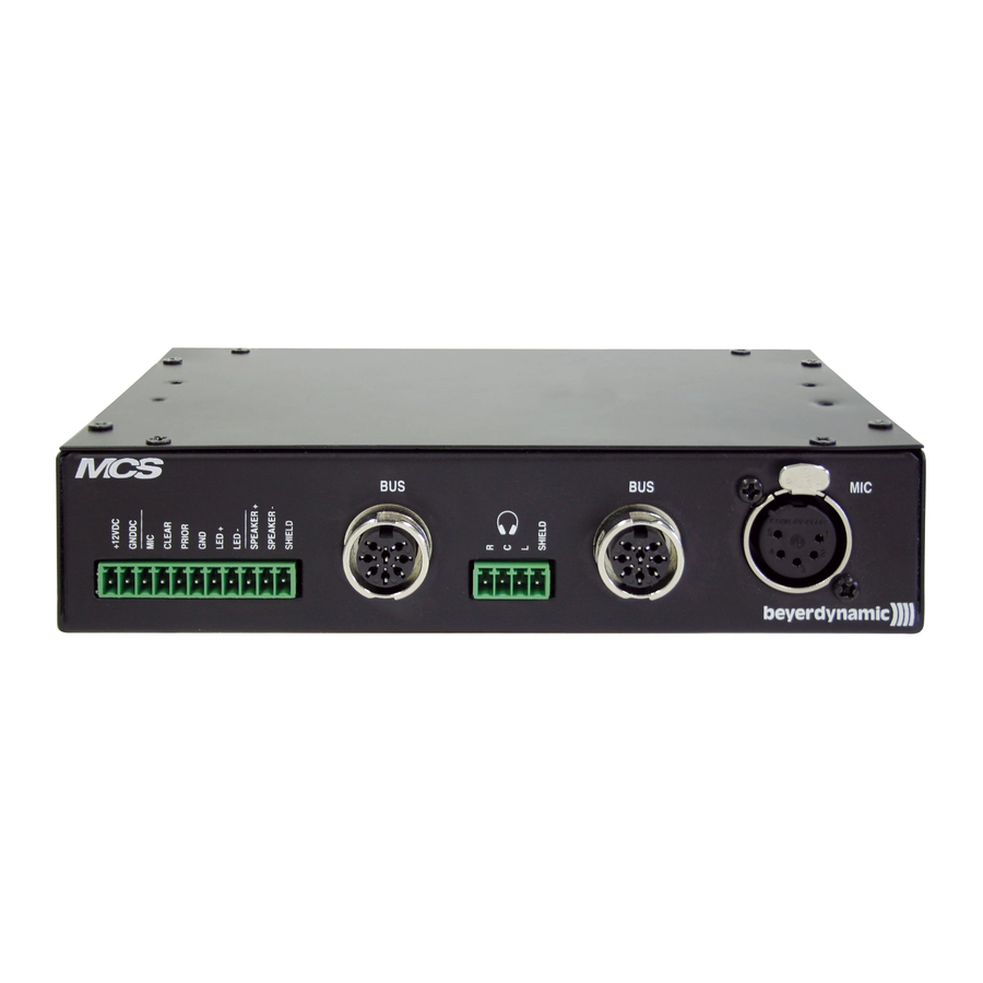
  • Page 54: Eléments De Commande

    . Veillez à ce que le connecteur soit bien enfoncé dans l’appareil MCS 20. Le porte-fusible intègre le fusible 3,15 AT. Prises à baïonnette • L’appareil d’alimentation MCS 20 est doté de prises à baïonnette pour le branchement d’appareils d’alimentation MCS 20 ainsi que de postes d’appel supplémentaires.
  • Page 55: Important

    être fermée. Important: En cas de montage du bloc d’alimentation MCS 20 dans un rack, veillez à ce que le rack soit mis à la masse (relié au fil pilote de l’installation électrique). Pour le montage dans un rack, veuillez utiliser des vis d’une taille minimum de M 6 x 15 mm.
  • Page 56: Postes D'appel

    Non-responsabilité • La société beyerdynamic GmbH & Co. KG décline toute responsabilité en cas de dommages sur le produit ou de blessures sur des personnes dus à une utilisation négligente, incorrecte ou contraire aux fins indiquées par le fabricant.
  • Page 57: Commande Du Poste Délégué Mcs 221

    MCS 20 – Poste d’appel MCS 221 Vue de dessous Vue de dessus Commutateur de configuration (commutateur DIP) Microphone à col de cygne avec anneau lumineux Touche de microphone avec DEL Haut-parleur 3.2.1 Commande du poste délégué MCS 221 • Pour parler, le microphone du poste délégué MCS 221 doit être activé. Lorsque le microphone est activé, l’anneau du col de cygne et la diode de la touche de microphone sont allumés.
  • Page 58: Commutateurs De Configuration

    MCS 20 – Poste d’appel MCS 221 3.2.2 Commutateurs de configuration • Sur le dessous des postes d’appel se trouvent des commutateurs de configuration permettant, selon réglage sur ON ou sur OFF, d’attribuer au poste les fonctions mentionnées dans le tableau. Pour programmer les fonctions du poste président MCS 223 différant des fonctions standard, veuillez vous reporter aux Chapitres 3.3.8 «Mode de...
  • Page 59 MCS 20 – Poste d’appel MCS 221 2 OFF – Le poste d’appel n’est pas pris en compte dans la limite en mode VOICE. Ce commutateur ne vaut que pour le poste délégué MCS 221. 3 OFF – La limite ne vaut pas pour ce poste d'appel.
  • Page 60: Eléments De Commande Poste Président Mcs 223

    MCS 20 – Poste d’appel MCS 223 3.3 Eléments de commande poste président MCS 223 Vue arrière Vue de dessus Prise conférence ; branchement du poste d’appel/vers le poste d’appel suivant ou raccordement à l’appareil d’alimentation Prise casque, jack 3,5 mm Prise conférence ;...
  • Page 61: Modes De Fonctionnement

    MCS 20 – Poste d’appel MCS 223 – Touche Prior (priorité) pour une brève interruption, p. ex. pour la diffusion d’un message – Touche Clear (effacement) pour la désactivation simultanée de tous les microphones délégués – Touches Limit pour la sélection du nombre autorisé de postes activés ou demandant la parole –...
  • Page 62: Circuit De Priorité (Prior)

    MCS 20 – Poste d’appel MCS 223 • La valeur sélectionnée pour le seuil d’activation est automatiquement mémorisée et chargée lors de chaque mise en marche de l’appareil d’alimentation. • Il est recommandé de régler le seuil d’activation sur le lieu même de la conférence. En effet, la distance entre les postes et l’acoustique de la salle exercent une influence sur l’activation des microphones.
  • Page 63: Mode De Fonctionnement

    MCS 20 – Poste d’appel MCS 223 • La limite vaut pour le mode de fonctionnement respectivement activé, indiqué via le témoin lumineux dans le champ «Mode». • Sélectionnez le mode de fonctionnement pour lequel la limite doit être déterminée. Le mode de fonctionnement choisi est indiqué...
  • Page 64 MCS 20 – Poste d’appel MCS 223 • Etape 1 – Réglage de la limite sur 01 Nous recommandons de régler la limite pour le mode de fonctionnement souhaité («Free» ou «Request») tout d’abord sur 01. En effet, en présence d’une limite >1, le temps de parole du poste d’appel activé en premier lieu vaut également pour tous les autres postes activés ultérieurement à...
  • Page 65: Mode De Programmation

    MCS 20 – Poste d’appel MCS 223 • Etape 4 – Quitter le mode Timer sans effaçage de microphones actifs Pressez la touche «Prior» et maintenez-la enfoncée, pressez brièvement la touche «Clear» . La limite pour le mode de fonctionnement activé apparaît de nouveau à l’écran Quitter le mode Timer avec effaçage de microphones actifs...
  • Page 66 MCS 20 – Poste d’appel MCS 223 • Etape 4 – Modification de la valeur réglée Pressez l’une des touches «Vol» jusqu’à ce que la valeur souhaitée apparaisse sur l’écran • Etape 5 – Retour à l’affichage de la fonction Pressez la touche Limit [+] ou [-] pour passer de l’affichage de la valeur réglée (point clignotant à...
  • Page 67 MCS 20 – Poste d’appel MCS 223 Pressez simultanément les touches «Voice» et «Requ» (presser tout d’abord la touche « Voice ») pour quitter le mode de programmation. Note: nous recommandons d’effectuer des enregistrements (p. ex. une copie du tableau de fonctions) des réglages mémorisés dans les setups.
  • Page 68: Tableau Fonctionnel De Programmation

    MCS 20 – Poste d’appel MCS 223 3.3.9 Tableau fonctionnel de programmation N° Description Plage de Réglage valeurs usine Mémorisation ou chargement des setups 1 ... 7 Volume sonore maximal 0 ... 32 Réglage du volume sonore via touches «Vol»...
  • Page 69 MCS 20 – Poste d’appel MCS 223 N° Description Plage de Réglage valeurs usine FiFo = Requ + Free: 0 ou 1 0 = MCS 223 ne désactive pas d’autres postes 1 = MCS 223 désactive d’autres postes FiFo = Requ + Free: 0 ou 1 0 = MCS 223 n’est pas désactivé...
  • Page 70: Exemple De Configuration Système

    MCS 20 – Configuration du système Exemple de configuration système Configuration avec un appareil d’alimentation MCS 20 autres MCS 221 MCS 20 MCS 221 MCS 221 MCS 223 Note: en tout, jusqu’à 60 postes d’appel peuvent être raccordés à un appareil d’alimentation.
  • Page 71: Spécifications Techniques

    MCS 20 – Configuration du système Configuration avec adaptateur T autres MCS 221 MCS 20 MCS 221 MCS 221 MCS 223 autres MCS 221 MCS 221 MCS 221 MCS 221 Note: un seul poste président MCS 223 peut être raccordé.
  • Page 72: Entretien

    MCS 20 – Equipement Entretien • Nettoyez les postes uniquement à l’aide d’un chiffon sec ou légèrement humidifié. N’utilisez jamais de solvants. Ces derniers peuvent endommager le dessus de l’appareil. Veillez à ce qu’aucun liquide ne pénètre dans la tête de microphone.
  • Page 73: Type De Câbles Recommandé En Cas De Fabrication Individuelle

    MCS 20 – Type de câbles Type de câbles recommandé en cas de fabrication individuelle...
  • Page 74: Ec Declaration Of Conformity

    Type of Equipment: Conference & Discussion System Model Numbers: MCS 20, MCS 221, MCS 223 I, the undersigned, as an employee of beyerdynamic, hereby declare that the equipment specified conforms to the above Directive and Standards. Manufacturer’s signature: Full Name:...
  • Page 76 GmbH & Co. KG Theresienstr. 8 74072 Heilbronn, Germany Tel. +49 (0 )71 31 / 6 17-0 Fax +49 (0 )71 31 / 617-224 E-mail: info@beyerdynamic.de Internet: www.beyerdynamic.de beyerdynamic U.K. Ltd. 17 Albert Drive Burgess Hill RH15 9TN Tel. +44 (0)1444 / 258 258 Fax +44 (0)1444 / 258 444 E-mail: sales@beyerdynamic.co.uk...

Table des Matières