ABB CM Serie Instructions De Montage Et De Mise En Service
Masquer les pouces
Voir aussi pour CM Serie:
- Instructions de montage et de mise en service (20 pages) ,
- Mode d'emploi (12 pages) ,
- Instructions de service et de montage (12 pages)
Table des Matières
Liens rapides
CM-MPS.23 / CM-MPS.43
CM-MPN.52 / CM-MPN.62
CM-MPN.72
(DE) Betriebs- und Montageanleitung
Multifunktionale Dreiphasenüberwachungs-
relais, CM Reihe
Hinweis: Diese Betriebs- und Montageanleitung enthält nicht
sämtliche
Detailinformationen
Produktreihe und kann auch nicht jeden Einsatzfall der
Produkte
berücksichtigen.
ausschließlich der Produktbeschreibung und sind nicht als
vertraglich
vereinbarte
Weiterführende Informationen und Daten erhalten Sie in den
Katalogen und Datenblättern der Produkte, über die örtliche
ABB-Niederlassung sowie auf der ABB Homepage unter
www.abb.com.
Technische
vorbehalten. In Zweifelsfällen gilt der deutsche Text.
Warnung! Gefährliche Spannung! Installation nur
durch
elektrotechnische
spezifische Vorschriften (z.B. VDE, etc.) beachten.
Vor
der
Montageanleitung sorgfältig lesen und beachten. An
die nicht beschrifteten Klemmen darf kein Leiter
angeschlossen werden.
(EN) Operating and installation instructions
Multifunction three-phase monitoring relays,
CM range
Note: These operating and installation instructions cannot
claim to contain all detailed information of all types of this
product range and can even not consider every possible
application of the products. All statements serve exclusively
to describe the product and have not to be understood as
contractually agreed characteristics. Further information and
data is obtainable from the catalogues and data sheets of
this product, from the local ABB sales organisations as well
as on the ABB homepage www.abb.com. Subject to change
without prior notice. The German text applies in cases of
doubt.
Warning! Hazardous voltage! Installation by person
with
electrotechnical
accordance with the specific national regulations
(e.g., VDE, etc). Before installing this unit, read these
operating and installation instructions carefully and
completely. Do not connect any conductor to
terminals not labelled.
(FR) Instructions de montage et de mise en service
Relais de contrôle multifonctions d'un réseau
triphasé, gamme CM
Note: Ces instructions de service et de montage ne
contiennent pas toutes les informations relatives à tous les
types de cette gamme de produits et ne peuvent pas non
plus tenir compte de tous les cas d'application. Toutes les
indications ne sont données qu'à titre de description du
produit et ne constituent aucune obligation contractuelle.
Pour de plus amples informations, veuillez-vous référer aux
catalogues et aux fiches techniques des produits, à votre
ABB STOTZ-KONTAKT GmbH, Eppelheimer Straße 82, 69123 Heidelberg / Germany; www.abb.com/lowvoltage
zu
allen
Typen
Alle
Angaben
Beschaffenheit
aufzufassen.
Änderungen
Fachkraft.
Installation
diese
Betriebs-
expertise
only
agence ABB ou sur notre site www.abb.com. Sous réserve de
modifications techniques. En cas de divergences, le texte
allemand fait foi.
Avertissement!
Installation uniquement par des personnes qualifiées
der
en électrotechnique et en conformité avec les
prescriptions nationales (p.e. VDE, etc.). Avant
dienen
l'installation de cet appareil veuillez lire l'intégralité de
ces instructions. Ne pas connecter de conducteur
aux bornes non marquées.
(ES) Instrucciones de montaje y de servicio
Relés de control trifásico multifuncionales,
jederzeit
serie CM
Nota:
Estas
informaciones detalladas relativas a todos los tipos del
Landes-
producto ni pueden considerar todos los casos de operación.
Todas las indicaciones son a título descriptivo del producto y
und
no constituyen ninguna obligación contractual. Para más
información,
características, la sucursal local de ABB o la Web www.abb.
com. Sujeto a cambios técnicos sin previo aviso. En caso de
duda, prevalece el texto alemán.
¡Advertencia! ¡Tensión peligrosa! La instalación
deberá ser realizada únicamente por electricistas
especializados. Es necesario respetar las normas
especificas del país (p.ej. VDE, etc.). Antes de la
instalación lea completamente estas instrucciones.
No conectar ningún conductor a los bornes no
marcados.
(IT) Istruzioni per l'uso ed il montaggio
Relè di controllo trifase multifunzione,
serie CM
Nota: Le presenti istruzioni per l'uso ed il montaggio non
contengono tutte le informazioni
gamma di prodotti e non possono trattare tutti i casi
applicativi. Tutte le indicazioni servono esclusivamente a
and
in
descrivere
obbligazione
consultare i cataloghi ed i data sheet dei prodotti, o la nostra
homepage www.abb.com, oppure rivolgersi alla filiale locale
di ABB. Ci riserviamo il diritto di effettuare eventuali modifiche
tecniche. In caso di discrepanze o fraintendimenti fa fede il
testo in lingua tedesca.
Avvertenza! Tensione pericolosa! Far installare solo da
un elettricista specializzato. Bisogna osservare le
specifiche norme nazionali p.e. VDE, etc.). Prima
dell'installazione leggere attentamente le seguenti
istruzioni. Non collegare nessun conduttore ai
morsetti non marcati.
Tension
électrique
instrucciones
no
contienen
consulte
los
catálogos,
di dettaglio sull'intera
il
prodotto
e
non
costituiscono
contrattuale.
Per
ulteriori
dangereuse!
todas
las
las
hojas
de
alcuna
informazioni
Table des Matières

Manuels Connexes pour ABB CM Serie


Sommaire des Matières pour ABB CM Serie
- Page 1 Pour de plus amples informations, veuillez-vous référer aux catalogues et aux fiches techniques des produits, à votre ABB STOTZ-KONTAKT GmbH, Eppelheimer Straße 82, 69123 Heidelberg / Germany; www.abb.com/lowvoltage...
- Page 2 его описания и не должна рассматриваться в качестве гарантированных характеристик, имеющих юридическую силу. Дополнительную информацию и данные можно получить из каталогов и листа тех. данных на настоящее изделие в местном представительстве компании АВВ, а также на сайте компании АВВ по адресу: www.abb. com. Возможны изменения без...
- Page 3 Examples: CM-MPS.xyS CM-MPS.xyP DIN ISO 2380-1 Form A 0.8 x 4 mm / 0.0315 x 0.157 in DIN ISO 8764-1 PZ 1 0.6...0.8 Nm Ø 4.5 mm / 0.177 in 7.08 lb.in 8 mm 1 x 0.5...4.0 mm² 0.315" 2 x 0.5...1.5 mm² 2 x 0.5...2.5 mm²...
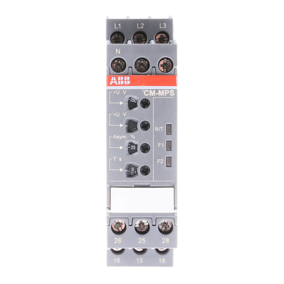
- Page 4 Deutsch Frontansicht mit Bedienelementen Betriebszustandsanzeige mit LEDs R/T: LED gelb - Anzeige Relais und Zeitablauf Relais angezogen Verzögerungszeit läuft F1: LED rot - Fehlermeldung F2: LED rot - Fehlermeldung Schwellwerteinstellung für Überspannung Schwellwerteinstellung für Unterspannung Schwellwerteinstellung für Asymmetrie (2-25 %) Einstellung der Auslöseverzögerung t (0 s;...
- Page 5 English Français Face avant et dispositifs de commande Front view with operating controls Indication de fonctionnement par LED Indication of operational states with LEDs R/T: LED jaune - Indication relais et temporisation R/T: yellow LED - Status indication relay and timing Relais activé...
- Page 6 Español Italiano Vista frontal con elementos de mando Vista frontale con gli elementi di comando Indicadores de servicio con LEDs LED di visualizzazione dello stato di funzionamento R/T: LED amarillo - Indicación relé y temporización R/T: LED giallo - Indicazione relè e temporizzazione Relé...
-
Page 7: Сообщения О Неисправностях
Русский Вид спереди на элементы управления Индикация состояния при помощи светодиодов R/T: желтый СИД - Индикация состояния реле и R/T: отсчета времени реле активировано Идет отсчет времени срабатывания реле F1: красный СИД - Сообщение о неисправности F2: красный СИД - Сообщение о неисправности Настройка... - Page 8 Deutsch IV Funktionsdiagramme (Abbildungen siehe Rückseite) a) Ansprechverzögerte Über- und Unterspannungsüberwachung, Verzögerungsart unverzögert oder verzögert (0,1-30 s) ab. Die 1 x 2 Wechsler Fehlerart wird durch LEDs angezeigt. Die Ausgangsrelais ziehen automatisch, je nach eingestellter Verzögerungsart unverzögert b) Rückfallverzögerte Über- und Unterspannungsüberwachung, 1 x 2 Wechsler oder verzögert (0,1-30 s) an, wenn die Spannung wieder in das Toleranzfenster zurückkehrt.
- Page 9 IV Function diagrams e) ON-delayed a) ON-delayed over- and undervoltage phase unbalance monitoring monitoring, 1 x 2 c/o contacts L1, L2, L3 L1, L2, L3 > U Unbalance > U - 5 % Unbalance -Hyst. Measured value Measured value L1, L2, L3 L1, L2 <...
- Page 10 Automatische Phasenfolgekorrektur Neutralleiterbruchüberwachung Automatic phase sequence correction Interrupted neutral monitoring Correction automatique de l‘ordre des phases Surveillance de coupure du neutre Corrección automática de la secuencia de fases Control de corte del neutro Correzione automatica della sequenza fasi Controllo dell‘interruzione del neutro Автоматическая...
-
Page 11: Function Diagrams
English IV Function diagrams falls below the set threshold value, the output relays de-energize a) ON-delayed over- and undervoltage monitoring, instantaneously or delayed (0.1-30 s), depending on the set time 1 x 2 c/o contacts delay. The fault type is indicated by LEDs. The output relays re- b) OFF-delayed over- and undervoltage monitoring, energize automatically, instantaneously or with delay (0.1-30 s), 1 x 2 c/o contacts... -
Page 12: Diagrammes De Fonctionnement
Français IV Diagrammes de fonctionnement relais de sortie sont activés. Si la tension à surveiller dépasse ou a) Surveillance de sous- et surtension temporisée au travail, chute en dessous de la valeur de seuil ajustée, les relais de sortie 1 x 2 inverseurs se désactivent, selon la temporisation sélectionnée, sans b) Surveillance de sous- et surtension temporisée au repos, temporisation ou avec temporisation (0,1-30 s). -
Page 13: Diagramas De Funcionamiento
Español IV Diagramas de funcionamiento a) Control de sobre- y subtensión con retardo a la conexión, con tensión correcta. Si la tensión monitorizada excede o cae 1 x 2 contactos conmutados por debajo del valor umbral ajustado, los relés de salida se des- energizan instantáneamente o con retardo (0,1-30 s), dependiendo b) Control de sobre- y subtensión con retardo a la desconexión, del tiempo ajustado. -
Page 14: Principio Di Funzionamento
Italiano IV Diagrammi di funzionamento a) Controllo di sotto- e sovratensione con ritardo all‘eccitazione, o diminuisce oltre il valore di soglia impostato, i relè di uscita si 1 x 2 contatti di scambio diseccitano, a seconda del modo di ritardo impostato, senza o con (0,1-30 s) ritardo. -
Page 15: Принцип Действия
Русский IV Функциональные схемы a) Задержка при включении, контроль перенапряжения и обесточиваются мгновенно или с задержкой (0,1-30 с), в пониженного напряжения, 1 x 2 перекидных контакта зависимости от заданного времени. Тип неисправности отображается светодиодными индикаторами. Выходные b) Задержка при выключении, контроль перенапряжения и реле... - Page 16 2 x 1 c/o 1 x 2 c/o 0.1-30 s 1 x 2 c/o 0.1-30 s 2 x 1 c/o 0.1-30 s 2 x 1 c/o 0.1-30 s 0.1-30 s 200 ms 250 ms CM-MPS.23 L1-L2-L3-N 180-280 V 180-220 V DIP2:OFF 2 x 1 c/o DIP3: ON...