Table des Matières

Publicité

Les langues disponibles

Les langues disponibles

Liens rapides

Quick Start
Thank you for purchasing the MSI
B360M BAZOOKA/ H370M
®
BAZOOKA
motherboard. This Quick Start section provides
demonstration diagrams about how to install your computer. Some
of the installations also provide video demonstrations. Please link
to the URL to watch it with the web browser on your phone or tablet.
You may have even link to the URL by scanning the QR code.
Kurzanleitung
Danke, dass Sie das MSI
B360M BAZOOKA/ H370M BAZOOKA
®
Motherboard gewählt haben. Dieser Abschnitt der Kurzanleitung
bietet eine Demo zur Installation Ihres Computers. Manche
Installationen bieten auch die Videodemonstrationen. Klicken Sie
auf die URL, um diese Videoanleitung mit Ihrem Browser auf Ihrem
Handy oder Table anzusehen. Oder scannen Sie auch den QR Code
mit Ihrem Handy, um die URL zu öffnen.
Présentation rapide
Merci d' avoir choisi la carte mère MSI
B360M BAZOOKA/ H370M
®
BAZOOKA. Ce manuel fournit une rapide présentation avec des
illustrations explicatives qui vous aideront à assembler votre
ordinateur. Des tutoriels vidéo sont disponibles pour certaines
étapes. Cliquez sur le lien fourni pour regarder la vidéo sur votre
téléphone ou votre tablette. Vous pouvez également accéder au lien
en scannant le QR code qui lui est associé.
Быстрый старт
Благодарим вас за покупку материнской платы MSI
B360M
®
BAZOOKA. В этом разделе представлена
BAZOOKA/ H370M
информация, которая поможет вам при сборке комьютера.
Для некоторых этапов сборки имеются видеоинструкции.
Для просмотра видео, необходимо открыть
соответствующую ссылку в веб-браузере на вашем телефоне
или планшете. Вы также можете выполнить переход по
ссылке, путем сканирования QR-кода.
I
Quick Start

Publicité

Table des Matières
loading

Sommaire des Matières pour MSI B360M BAZOOKA

  • Page 1 Handy oder Table anzusehen. Oder scannen Sie auch den QR Code mit Ihrem Handy, um die URL zu öffnen. Présentation rapide Merci d’ avoir choisi la carte mère MSI B360M BAZOOKA/ H370M ® BAZOOKA. Ce manuel fournit une rapide présentation avec des illustrations explicatives qui vous aideront à...
  • Page 2 Installing a Processor/ Installation des Prozessors/ Installer un processeur/ Установка процессора https://youtu.be/4ce91YC3Oww Quick Start...
  • Page 3 Installing DDR4 memory/ Installation des DDR4-Speichers/ Installer une mémoire DDR4/ Установка памяти DDR4 http://youtu.be/T03aDrJPyQs DIMMB2 DIMMB2 DIMMB1 DIMMA2 DIMMA2 DIMMA2 DIMMA1 Quick Start...
  • Page 4 Connecting the Front Panel Header/ Anschließen der Frontpanel-Stiftleiste/ Connecter un connecteur du panneau avant/ Подключение разъемов передней панели http://youtu.be/DPELIdVNZUI HDD LED + Power LED + HDD LED - Power LED - Reset Switch Power Switch Reset Switch Power Switch JFP1 Reserved No Pin JFP1...
  • Page 5 Installing the Motherboard/ Installation des Motherboards/ Installer la carte mère/ Установка материнской платы Quick Start...
  • Page 6 Installing SATA Drives/ Installation der SATA-Laufwerke/ Installer le disque dur SATA/ Установка дисков SATA http://youtu.be/RZsMpqxythc Quick Start...
  • Page 7 Installing a Graphics Card/ Einbau der Grafikkarte/ Installer une carte graphique/ Установка дискретной видеокарты http://youtu.be/mG0GZpr9w_A Quick Start...
  • Page 8 Connecting Peripheral Devices/ Peripheriegeräte/ Connecter un périphérique anschliessen/ Подключение периферийных устройств VIII Quick Start...
  • Page 9 Connecting the Power Connectors/ Stromanschlüsse anschliessen/ Connecter les câbles du module d’ alimentation/ Подключение разъемов питания http://youtu.be/gkDYyR_83I4 ATX_PWR1 CPU_PWR1 Quick Start...
  • Page 10 Power On/ Einschalten/ Mettre sous-tension/ Включение питания Quick Start...
  • Page 11: Table Des Matières

    Contents Safety Information ....................2 Specifications ......................3 Rear I/O Panel ....................... 8 LAN Port LED Status Table..................8 Realtek HD Audio Manager ..................8 Overview of Components ..................10 CPU Socket ......................11 DIMM Slots ......................12 PCI_E1~3: PCIe Expansion Slots ................13 SATA1~6: SATA 6Gb/s Connectors ...............
  • Page 12: Safety Information

    Safety Information y The components included in this package are prone to damage from electrostatic discharge (ESD). Please adhere to the following instructions to ensure successful computer assembly. y Ensure that all components are securely connected. Loose connections may cause the computer to not recognize a component or fail to start.
  • Page 13: Specifications

    * The SATA1 connector will be unavailable when a SATA M.2 SSD has been installed in the M.2_1 slot. ** Before using Intel Optane™ memory modules, please ensure that you have ® updated the drivers and BIOS to the latest version from MSI website. RAID Intel H370 Chipset ®...
  • Page 14 Continued from previous page y Intel B360/ H370 Chipset ® ƒ 6x USB 3.1 Gen1 (SuperSpeed USB) ports (3 Type-A & 1 Type-C ports on the back panel, 2 ports available through the internal USB connector) ƒ 6x USB 2.0 (High-speed USB) ports (2 Type-A ports on the back panel, 4 ports available through the internal USB connectors) y Realtek...
  • Page 15 Continued from previous page y 1x 24-pin ATX main power connector y 1x 8-pin ATX 12V power connector y 6x SATA 6Gb/s connectors y 1x USB 3.1 Gen1 connector (supports additional 2 USB 3.1 Gen1 ports) y 2x USB 2.0 connectors (supports additional 4 USB 2.0 ports) y 1x 4-pin CPU fan connector y 2x 4-pin system fan connectors...
  • Page 16 Software y X-BOOST y GAMING APP y SUPER CHARGER y MYSTIC LIGHT y Open Broadcaster Software (OBS) y CPU-Z MSI GAMING y Intel Extreme Tuning Utility ® y Google Chrome™ ,Google Toolbar, Google Drive y Norton™ Internet Security Solution Continued on next page...
  • Page 17 Continued from previous page y Audio ƒ Audio Boost ƒ Voice Boost y Storage ƒ Turbo M.2 y Fan ƒ Smart Fan Control y LED ƒ Mystic Light Extension(RGB) ƒ Mystic light SYNC ƒ EZ DEBUG LED y Protection ƒ PCI-E Steel Armor Special Features y Performance...
  • Page 18: Rear I/O Panel

    Rear I/O Panel Line-in Line-out PS/2 Mouse USB 3.1 Gen1 PS/2 Keyboard DVI-D USB 2.0 USB 3.1 Gen1 Mic in Type-C LAN Port LED Status Table Link/ Activity LED Speed LED Status Description Status Description No link 10 Mbps connection Yellow Linked Green...
  • Page 19 When you plug into a device at an audio jack, a dialogue window will pop up asking you which device is current connected. (H370M BAZOOKA) (B360M BAZOOKA) Each jack corresponds to its default setting as shown on the next page. Rear I/O Panel...
  • Page 20: Overview Of Components

    Overview of Components CPU Socket CPU_PWR1 DIMMA1 DIMMA2 CPU_FAN1 DIMMB1 DIMMB2 SYS_FAN2 ATX_PWR1 SYS_FAN1 JUSB3 JBAT1 PCI_E1 SATA▼1▲2 M2_1 SATA4 PCI_E2 SATA3 JRGB1 PCI_E3 JTBT1 JFP1 SATA5 JAUD1 SATA6 JCOM1 JCI1 JLPT1 JFP2 JTPM1 JUSB2 JUSB1 Overview of Components...
  • Page 21: Cpu Socket

    Always unplug the power cord from the power outlet before installing or removing the CPU. Please retain the CPU protective cap after installing the processor. MSI will deal with Return Merchandise Authorization (RMA) requests if only the motherboard comes with the protective cap on the CPU socket.
  • Page 22: Dimm Slots

    DIMM Slots DIMMA1 DIMMB1 Channel A Channel B DIMMA2 DIMMB2 Memory module installation recommendation DIMMB2 DIMMB2 DIMMB1 DIMMA2 DIMMA2 DIMMA2 DIMMA1 Important Always insert memory modules in the DIMMA2 slot first. Due to chipset resource usage, the available capacity of memory will be a little less than the amount of installed.
  • Page 23: Pci_E1~3: Pcie Expansion Slots

    PCI_E3: PCIe 3.0 x1 (PCH lanes) Important If you install a large and heavy graphics card, you need to use a tool such as MSI Gaming Series Graphics Card Bolster to support its weight to prevent deformation of the slot.
  • Page 24: M2_1: M.2 Slot (Key M)

    M2_1: M.2 Slot (Key M) Important Intel RST only supports PCIe M.2 SSD with UEFI ROM, ® does not support Legacy ROM. Video Demonstration Watch the video to learn how to Install M.2 SSD. http://youtu.be/JCTFABytrYA Installing M.2 SSD 1. Loosen the M.2 riser screw from the motherboard.
  • Page 25: Jfp1, Jfp2: Front Panel Connectors

    JFP1, JFP2: Front Panel Connectors These connectors connect to the switches and LEDs on the front panel. JFP1 HDD LED + Power LED + HDD LED - Power LED - Reset Switch Power Switch Reset Switch Power Switch Reserved No Pin Speaker - Buzzer + JFP2...
  • Page 26: Jusb1, Jusb2: Usb 2.0 Connectors

    JUSB1, JUSB2: USB 2.0 Connectors These connectors allow you to connect USB 2.0 ports on the front panel. USB0- USB1- USB0+ USB1+ Ground Ground No Pin Important Note that the VCC and Ground pins must be connected correctly to avoid possible damage.
  • Page 27: Jcom1: Serial Port Connector

    JCOM1: Serial Port Connector This connector allows you to connect the optional serial port with bracket. SOUT Ground No Pin JAUD1: Front Audio Connector This connector allows you to connect audio jacks on the front panel. MIC L Ground MIC R Head Phone R MIC Detection SENSE_SEND...
  • Page 28: Cpu_Fan1, Sys_Fan1~2: Fan Connectors

    CPU_FAN1, SYS_FAN1~2: Fan Connectors Fan connectors can be classified as PWM (Pulse Width Modulation) Mode or DC Mode. PWM Mode fan connectors provide constant 12V output and adjust fan speed with speed control signal. DC Mode fan connectors control fan speed by changing voltage. When you plug a 3-pin (Non-PWM) fan to a fan connector in PWM mode, the fan speed will always maintain at 100%, which might create a lot of noise.
  • Page 29: Jci1: Chassis Intrusion Connector

    JCI1: Chassis Intrusion Connector This connector allows you to connect the chassis intrusion switch cable. Normal Trigger the chassis intrusion event (default) Using chassis intrusion detector 1. Connect the JCI1 connector to the chassis intrusion switch/ sensor on the chassis. 2.
  • Page 30: Jtpm1: Tpm Module Connector

    JTPM1: TPM Module Connector This connector is for TPM (Trusted Platform Module). Please refer to the TPM security platform manual for more details and usages. LPC Clock 3V Standby power LPC Reset 3.3V Power LPC address & data pin0 Serial IRQ LPC address &...
  • Page 31: Jrgb1: Rgb Led Connector

    Always turn off the power supply and unplug the power cord from the power outlet before installing or removing the RGB LED strip. Please use MSI’ s software to control the extended LED strip. EZ Debug LED These LEDs indicate the debug status of the motherboard.
  • Page 32: Bios Setup

    Press Delete key, when the Press DEL key to enter Setup Menu, F11 to enter Boot Menu message appears on the screen during the boot process. y Use MSI FAST BOOT application. Click on GO2BIOS button and choose OK. The system will reboot and enter BIOS setup directly.
  • Page 33: Resetting Bios

    Updating BIOS Updating BIOS with M-FLASH Before updating: Please download the latest BIOS file that matches your motherboard model from MSI website. And then save the BIOS file into the USB flash drive. Updating BIOS: 1. Insert the USB flash drive that contains the update file into the computer.
  • Page 34: Ez Mode

    EZ Mode At EZ mode, it provides the basic system information and allows you to configure the basic setting. To configure the advanced BIOS settings, please enter the Advanced Mode by pressing the Setup Mode switch or F7 function key. XMP switch Setup Mode switch Screenshot...
  • Page 35 y Information display - click on the CPU, Memory, Storage, Fan Info and Help buttons on left side to display related information. y Function buttons - enable or disable the LAN Option ROM, M.2/ Optane Genie, HD audio controller, AHCI, RAID, CPU Fan Fail Warning Control and BIOS Log Review by clicking on their respective button.
  • Page 36: Advanced Mode

    Advanced Mode Press Setup Mode switch or F7 function key can switch between EZ Mode and Advanced Mode in BIOS setup. XMP switch Setup Mode switch Screenshot Search Language System information Boot device priority bar BIOS menu BIOS menu selection selection Menu display y XMP switch/ Setup Mode switch/ Screenshot/ Language/ System information/ Boot...
  • Page 37: Oc Menu

    OC Menu This menu is for advanced users who want to overclock the motherboard. Important Overclocking your PC manually is only recommended for advanced users. Overclocking is not guaranteed, and if done improperly, it could void your warranty or severely damage your hardware. f OC Explore Mode [Normal] Enables or disables to show the normal or expert version of OC settings.
  • Page 38 f CPU Ratio Offset When Running AVX [Auto] Sets a offset value to lower the CPU core ratio. It could be helpful for heat dissipation when running AVX instruction set. If set to Auto, BIOS will configure this setting automatically. This item appears when the installed CPU supports this function. f Ring Ratio [Auto] Sets the ring ratio.
  • Page 39 f Memory Try It ! [Disabled] It improve memory compatibility or performance by choosing optimized memory preset. f DRAM Timing Mode [Link] Selects the memory timing mode. [Link] Allows user to configure the DRAM timing for all memory channel. [UnLink] Allows user to configure the DRAM timing for respective memory channel.
  • Page 40 f MEMORY-Z Press Enter to enter the sub-menu. This sub-menu displays all the settings and timings of installed memory. You can also access this information menu at any time by pressing [F5]. fDIMMA1/A2/B1/B2 Memory SPD Press Enter to enter the sub-menu. The sub-menu displays the information of installed memory.
  • Page 41 fAdjacent Cache Line Prefetch [Enabled] Enables or disables the CPU hardware prefetcher (MLC Spatial prefetcher). [Enabled] Enables adjacent cache line prefetching for reducing the cache latency time and tuning the performance to the specific application. [Disabled] Enables the requested cache line only. fCPU AES Instructions [Enabled] Enables or disables the CPU AES (Advanced Encryption Standard-New Instructions) support.
  • Page 42 fCPU Current Limit (A) [Auto] Sets maximum current limit of CPU package in Turbo Boost mode. When the current is over the specified value, the CPU will automatically reduce the core frequency for reducing the current. fFCLK Frequency [Auto] Sets FCLK frequency. Lower FCLK frequency may help you to set higher base clock frequency.
  • Page 43: Software Description

    7. Follow the instructions on the screen to install Windows ® Installing Drivers 1. Start up your computer in Windows ® 2. Insert MSI Driver Disc into your optical drive. ® 3. The installer will automatically appear and it will find and list all necessary drivers.
  • Page 44 NOTE Software Description...
  • Page 45 Inhalt Sicherheitshinweis ....................2 Spezifikationen ...................... 3 Rückseite E/A ......................8 LAN Port LED Zustandstabelle ................8 Realtek HD Audio Manager ..................8 Übersicht der Komponenten ................10 CPU Sockel ......................11 DIMM-Steckplätze ....................12 PCI_E1~3: PCIe Erweiterungssteckplätze ............13 SATA1~6: SATA 6Gb/s Anschlüsse ...............
  • Page 46: Sicherheitshinweis

    Sicherheitshinweis y Die im Paket enthaltene Komponenten sind der Beschädigung durch elektrostatischen Entladung (ESD). Beachten Sie bitte die folgenden Hinweise, um die erfolgreichen Computermontage sicherzustellen. y Stellen Sie sicher, dass alle Komponenten fest angeschlossen sind. Lockere Steckverbindungen können Probleme verursachen, zum Beispiel: Der Computer erkennt eine Komponente nicht oder startet nicht.
  • Page 47: Spezifikationen

    Modul im M.2_1-Steckplatz installieren. ** Bevor Sie Intel Optane Speichermodule verwenden, stellen Sie bitte über ® ™ Downloads von der MSI Website sicher, dass die Treiber und das BIOS auf dem neuesten Stand sind. RAID Intel H370 Chipsatz ® (Nur für H370M y Unterstützt RAID 0, RAID1, RAID 5 und RAID 10 für SATA...
  • Page 48 Fortsetzung der vorherigen Seite y Intel B360/ H370 Chipsatz ® ƒ 6x USB 3.1 Gen1 (SuperSpeed USB) Anschlüsse (3 Typ-A & 1 Typ-C an der rückseitigen Anschlussleiste, 2 Anschlüsse stehen durch die internen USB Anschluss zur Verfügung) ƒ 6x USB 2.0 (High-speed USB) Anschlüsse (2 Typ-A an der rückseitigen Anschlussleiste, 4 Anschlüsse stehen durch die internen USB Anschluss zur Verfügung) y Realtek...
  • Page 49 Fortsetzung der vorherigen Seite y 1x 24-poliger ATX Stromanschluss y 1x 8-poliger ATX 12 V Stromanschluss y 6x SATA 6Gb/s Anschlüsse y 1x USB 3.1 Gen1 Anschluss (unterstützt zusätzliche 2 USB 3.1 Gen1-Ports) y 2x USB 2.0 Anschlüsse (unterstützt zusätzliche 4 USB 2.0-Ports) y 1x 4-poliger CPU-Lüfter-Anschluss y 2x 4-polige System-Lüfter-Anschlüsse...
  • Page 50 FAST BOOT Software y X-BOOST y GAMING APP y SUPER CHARGER y MYSTIC LIGHT y Open Broadcaster Software (OBS) y CPU-Z MSI GAMING y Intel Extreme Tuning Utility ® y Google Chrome , Google Toolbar, Google Drive ™ y Norton Internet Security Solution ™...
  • Page 51: Besondere Funktionen

    Fortsetzung der vorherigen Seite y Audio ƒ Audio Boost ƒ Voice Boost y Speicherung ƒ Turbo M.2 y Lüfter ƒ Smart-Lüftersteuerung y LED ƒ Mystic Light Extension(RGB) ƒ Mystic Light SYNC ƒ EZ DEBUG LED y Schutz ƒ PCI-E Steel Armor Besondere Funktionen y Leistung...
  • Page 52: Rückseite E/A

    Rückseite E/A Line-In Line-Out PS/2 Maus USB 3.1 Gen1 PS/2 Tastatur DVI-D USB 2.0 USB 3.1 Gen1 Mic In Typ-C LAN Port LED Zustandstabelle Verbindung/ Aktivität LED Geschwindigkeit LED Zustand Bezeichnung Zustand Bezeichnung Keine Verbindung 10 Mbps-Verbindung Gelb Verbindung Grün 100 Mbps-Verbindung Blinkt Datenaktivität...
  • Page 53 Auto Popup-Dialog Nach dem Anschluss eines Audio-Klinkensteckers erscheint ein Dialogfenster und fragt nach einer Bestätigung für das angeschlossene Gerät. (H370M BAZOOKA) (B360M BAZOOKA) Jede Buchse entspricht diesem Wert der Grundeinstellung, wie es auf den nächsten Seiten gezeigt wird. Rückseite E/A...
  • Page 54: Übersicht Der Komponenten

    Übersicht der Komponenten CPU Sockel CPU_PWR1 DIMMA1 CPU_FAN1 DIMMA2 DIMMB1 DIMMB2 SYS_FAN2 ATX_PWR1 SYS_FAN1 JUSB3 JBAT1 PCI_E1 SATA▼1▲2 M2_1 SATA4 PCI_E2 SATA3 JRGB1 PCI_E3 JTBT1 JFP1 SATA5 JAUD1 SATA6 JCOM1 JCI1 JLPT1 JFP2 JTPM1 JUSB2 JUSB1 Übersicht der Komponenten...
  • Page 55: Cpu Sockel

    Sie jedoch bitte sicher, dass die betroffenen Komponenten mit den abweichenden Einstellungen während des Übertaktens zurecht kommen. Von jedem Versuch des Betriebes außerhalb der Produktspezifikationen kann nur abgeraten werden. MSI übernehmt keinerlei Garantie für die Schäden und Risiken, die aus einem unzulässigem Betrieb oder einem Betrieb außerhalb der Produktspezifikation resultieren.
  • Page 56: Dimm-Steckplätze

    DIMM-Steckplätze DIMMA1 DIMMB1 Kanal A Kanal B DIMMA2 DIMMB2 Speichermodul-Installationsempfehlung DIMMB2 DIMMB2 DIMMB1 DIMMA2 DIMMA2 DIMMA2 DIMMA1 Wichtig Um einen sicheren Systemstart zu gewährleisten, bestücken Sie immer DIMMA2 zuerst. Aufgrund der Chipsatzressourcennutzung wird die verfügbare Kapazität des Speichers kleiner sein als die Größe der installierten Speicherkapazität. Basierend auf der Intel CPU Spezifikation wird eine Speicherspannung unter 1,35 Volt vorgeschlagen, um die CPU zu schützen.
  • Page 57: Pci_E1~3: Pcie Erweiterungssteckplätze

    PCI_E1~3: PCIe Erweiterungssteckplätze PCI_E1: PCIe 3.0 x16 (CPU Lanes) PCI_E2: PCIe 3.0 x1 (PCH Lanes) PCI_E3: PCIe 3.0 x1 (PCH Lanes) Wichtig Wenn Sie eine große und schwere Grafikkarte einbauen, benötigen Sie einen Grafikkarten-Stabilisator (Graphics Card Bolster) der das Gewicht trägt und eine Verformung des Steckplatzes vermeidet.
  • Page 58: M2_1: M.2 Steckplatz (Key M)

    M2_1: M.2 Steckplatz (Key M) Wichtig Intel RST unterstützt nur PCIe M.2 SSD mit UEFI ROM, ® Legacy-ROM wird NICHT unterstützt. Video-Demonstration In diesem Video erfahren Sie, wie Sie die M.2 SSD installieren. http://youtu.be/JCTFABytrYA Installation einer M.2 SSD 1. Lösen Sie die M.2- Schraube aus dem Motherboard.
  • Page 59: Jfp1, Jfp2: Frontpanel-Anschlüsse

    JFP1, JFP2: Frontpanel-Anschlüsse Diese Anschlüsse verbinden die Schalter und LEDs des Frontpanels. JFP1 HDD LED + Power LED + HDD LED - Power LED - Reset Switch Power Switch Reset Switch Power Switch Reserved No Pin Speaker - Buzzer + JFP2 Buzzer - Speaker +...
  • Page 60: Jusb1, Jusb2: Usb 2.0 Anschlüsse

    Bitte beachten Sie, dass Sie die mit VCC (Stromführende Leitung) und Ground (Erdung) bezeichneten Pins korrekt verbinden müssen, ansonsten kann es zu Schäden kommen. Um ein iPad, iPhone und einen iPod über USB-Anschlüsse aufzuladen, installieren Sie bitte die MSI SUPER CHARGER Software. ® JUSB3: USB 3.1 Gen1 Anschluss Mit diesem Anschluss können Sie die USB 3.1 Gen1 Anschlüsse auf dem Frontpanel...
  • Page 61: Jcom1: Serieller Anschluss

    JCOM1: Serieller Anschluss Mit diesem Anschluss können Sie das optionale serielle Schnittstelle mit dem Einbausatze verbinden. SOUT Ground No Pin JAUD1: Audioanschluss des Frontpanels Dieser Anschluss ermöglicht den Anschluss von Audiobuchsen eines Frontpanels. MIC L Ground MIC R Head Phone R MIC Detection SENSE_SEND No Pin...
  • Page 62: Cpu_Fan1, Sys_Fan1~2: Stromanschlüsse Für Lüfter

    CPU_FAN1, SYS_FAN1~2: Stromanschlüsse für Lüfter Diese Anschlüsse können im PWM (Pulse Width Modulation) Modus oder Spannungsmodus betrieben werden. Im PWM-Modus bieten die Lüfteranschlüsse konstante 12 V Ausgang und regeln die Lüftergeschwindigkeit per Drehzahlsteuersignal. Im DC-Modus bestimmen die Lüfteranschlüsse die Lüftergeschwindigkeit durch Ändern der Spannung. Wenn Sie ein 3-Pin (Non-PWM) Lüfter an einen PWM-Modus Lüfteranschluss anschließen, läuft der Lüfter mit höchster Drehzahl und kann unangenehm laut werden.
  • Page 63: Jci1: Gehäusekontaktanschluss

    JCI1: Gehäusekontaktanschluss Dieser Anschluss wird mit einem Kontaktschalter verbunden. Normal Löse den Gehäuseeingriff aus (Standardwert) Gehäusekontakt-Detektor verwenden 1. Schließen Sie den JCI1-Anschluss am Gehäusekontakt-Schalter/ Sensor am Gehäuse an. 2. Schließen Sie die Gehäuseabdeckung. 3. Gehen Sie zu BIOS > Settings > Security > Chassis Intrusion Configuration. 4.
  • Page 64: Jtpm1: Tpm Anschluss

    JTPM1: TPM Anschluss Dieser Anschluss wird für das TPM Modul (Trusted Platform Module) verwendet. Weitere Informationen über den Einsatz des optionalen TPM Modules entnehmen Sie bitte dem TPM Plattform Handbuch. LPC Clock 3V Standby power LPC Reset 3.3V Power LPC address & data pin0 Serial IRQ LPC address &...
  • Page 65: Jrgb1: Rgb Led Anschluss

    Schalten Sie die Stromversorgung aus und ziehen Sie das Netzkabel ab, bevor Sie die RGB-LED-Streifen ein- und ausbauen. Bitte verwenden Sie die MSI-Software zur Steuerung des LED-Leuchtstreifens. EZ Debug LED Diese LEDs zeigen den Status des Motherboards an. CPU - CPU wird nicht erkannt oder ist fehlerhaft.
  • Page 66: Bios Setup

    Während des BOOT-Vorgangs drücken Sie die Taste ENTF, wenn die Meldung Press DEL key to enter Setup Menu, F11 to enter Boot Menu erscheint. y Verwenden Sie die MSI FAST BOOT Anwendung. Klicken Sie die GO2BIOS-Taste und drücken Sie OK. Das System startet neu und geht direkt ins BIOS.
  • Page 67: Reset Des Bios

    Aktualisierung des BIOS mit dem M-FLASH-Programm Vorbereitung: Laden Sie bitte die neueste BIOS Version, die dem Motherboard-Modell entspricht, von der offiziellen MSI Website herunter und speichern Sie die BIOS-Datei auf USB-Flash- Laufwerk. BIOS-Aktualisierungsschritte: 1. Schließen das USB-Flashlaufwerk mit der BIOS-Datei an den Computer.
  • Page 68: Ez Modus

    EZ Modus Im EZ-Modus können Sie die Grundinformationen des Systems einsehen und grundlegende Einstellungen konfigurieren. Um sich die erweiterten BIOS- Einstellungen anzeigen zu lassen, aktivieren Sie bitte den Erweiterten Modus durch Drücken des Setup Modus Schalter oder der Funktionstaste F7. XMP Schalter Setup Modus Schalter Screenshot...
  • Page 69 y Informationsanzeige - Klicken Sie auf die Schaltfläche CPU, Memory, Storage, Fan Info und Help auf der linken Seite, um die jeweiligen Informationen anzuzeigen. y Funktionstasten - Aktivieren oder deaktivieren Sie LAN Option ROM, M.2/ Optane Genie, HD Audio Controller, AHCI, RAID, CPU Fan Fail Warning Control und BIOS Log Review durch Anklicken der zugehörigen Schaltfläche.
  • Page 70: Erweiterter Modus

    Erweiterter Modus Drücken Sie den Setup Modus Schalter oder die Funkionstaste F7, um zwischen dem EZ-Modus und Erweiterten-Modus im BIOS-Setup zu wechseln. XMP Schalter Setup Modus Schalter Screenshot Suchen Sprache System- information Bootgeräte- Prioritätsleiste BIOS-Menü BIOS-Menü -Auswahl -Auswahl Menüanzeige y XMP Schalter/ Setup Modus Schalter/ Screenshot/ Sprache/ Systeminformation/ Boot-Geräte Prioritätsleiste - Finden Sie die Informationen in den Beschreibungen der EZ Modus-Abschritt.
  • Page 71: Oc Menü

    OC Menü In diesem Menü können Benutzer das BIOS anpassen und das Mainboard übertakten. Bitte führen Sie nur Änderungen durch, wenn Sie sich über das Ergebnis im Klaren sind. Sie sollten Erfahrung beim Übertakten haben, da Sie sonst das Motherboard oder Komponenten des Systems beschädigen können.
  • Page 72 f Adjusted CPU Frequency Zeigt die eingestellte Frequenz der CPU an. Es handelt sich um eine Anzeige – Änderungen sind nicht möglich. f Core X X of X xxxx MHz [Auto]* Hier können Sie die CPU Taktraten der verschiedenen aktiven Kerne anpassen. Diese Optionen kann nur geändert werden, wenn CPU Ratio Apply Mode auf Per Core eingestellt.
  • Page 73 f Extreme Memory Profile (X.M.P.) [Disabled] Extreme Memory Profile (XMP) basieren auf Zertifizierungen für Speichermodule aus dem PC-Bereich. Aktivieren Sie die Funktion XMP oder wählen Sie ein Profil des Speichermoduls zum Übertakten aus. Diese Option steht zur Verfügung, wenn die installierten Speichermodule die XMP Technik unterstützen.
  • Page 74 f DRAM Voltages control [Auto] Erlaubt das Einstellen der DRAM-Spannungen. Wenn die Einstellung auf Auto gesetzt ist, wird das BIOS die Spannungen automatisch einstellen oder Sie können es manuell einstellen. f CPU Memory Changed Detect [Enabled]* Aktiviert/Deaktiviert die Systemwarnmeldung beim Booten, wenn die CPU oder der Hauptspeicher ersetzt wurde.
  • Page 75 fIntel Virtualization Tech [Enabled] Aktiviert oder deaktiviert die Intel Virtualization Technologie. [Enabled] Aktiviert die Intel Virtualization-Technologie, die es mehreren Betriebssystemen ermöglicht, in voneinander unabhängigen Partitionen zu arbeiten. Das System kann als mehrere Systeme virtuell einsetzen. [Disabled] Deaktiviert diese Funktion. fIntel VT-D Tech [Disabled] Aktiviert oder deaktiviert die Intel VT-D (Intel Virtualization for Directed I/O) Technologie.
  • Page 76 fPackage C State limit [Auto] Hier können Sie einen CPU C-State-Modus für Stromsparen auswählen, wenn das System im Leerlauf ist. Die Optionen des C-States ist abhängig von der installierten CPU. Diese Option wird angezeigt, wenn Intel C-State aktiviert ist. fCFG Lock [Enabled] Sperren oder Entsperren des MSR 0xE2[15]s, des CFG Lock-Bits.
  • Page 77: Softwarebeschreibung

    Softwarebeschreibung Laden Sie die neuesten Treiber und Dienstprogramme von www.msi.com herunter und aktualisieren Sie sie. Installation von Windows ® 1. Schalten Sie den Computer ein. 2. Legen Sie die Windows 10 Disk in das optisches Laufwerk. ® 3. Drücken Sie die Taste Restart auf dem Computergehäuse.
  • Page 78 Anmerkung Softwarebeschreibung...
  • Page 79 Table des matières Informations de sécurité ..................2 Spécifications ......................3 Panneau arrière Entrée/ Sortie ................8 Tableau explicatif de l’ état de la LED du port LAN ..........8 Realtek HD Audio Manager ..................8 Vue d’ ensemble des composants ............... 10 Socket processeur ....................
  • Page 80: Informations De Sécurité

    Informations de sécurité y Les composants dans l’ emballage peuvent être endommagés par des décharges électrostatiques (ESD). Pour vous assurer de correctement monter votre ordinateur, veuillez vous référer aux instructions ci-dessous. y Assurez-vous de bien connecter tous les composants. En cas de mauvaise connexion, il se peut que l’...
  • Page 81: Spécifications

    Support non-ECC, mémoire un-buffered y Support Intel Extreme Memory Profile (XMP) ® * Veuillez vous référer au site www.msi.com pour plus d’ informations sur la mémoire compatible. y 1 x slot PCIe 3.0 x16 Slots d’ extension y 2 x slots PCIe 3.0 x1 y 1 x port DVI-D, supportant une résolution maximum de...
  • Page 82 Suite du tableau de la page précédente y Chipset Intel B360/ H370 ® ƒ 6 x ports USB 3.1 Gen1 (SuperSpeed USB) (3 ports Type-A et 1 port Type-C sur le panneau arrière, 2 ports disponibles par l’ intermédiaire du connecteur USB interne) ƒ...
  • Page 83: Connecteurs Internes

    Suite du tableau de la page précédente y 1 x connecteur d’ alimentation principal ATX 24 broches y 1 x connecteur d’ alimentation ATX 12V 8 broches y 6 x connecteurs SATA 6 Gb/s y 1 x connecteur USB 3.1 Gen1 (support de 2 autres ports USB 3.1 Gen1) y 2 x connecteurs USB 2.0 (support de 4 autres ports USB 2.0)
  • Page 84 Logiciel y X-BOOST y GAMING APP y SUPER CHARGER y MYSTIC LIGHT y Open Broadcaster Software (OBS) y CPU-Z MSI GAMING y Intel Extreme Tuning Utility ® y Google Chrome™, Google Toolbar et Google Drive y Norton™ Internet Security Solution Suite du tableau sur la page suivante Spécifications...
  • Page 85 Suite du tableau de la page précédente y Audio ƒ Audio Boost ƒ Voice Boost y Stockage ƒ Turbo M.2 y Ventilateur ƒ Contrôle des ventilateurs y LED ƒ Mystic Light Extension(RGB) ƒ Mystic light SYNC ƒ EZ DEBUG LED y Protection ƒ...
  • Page 86: Panneau Arrière Entrée/ Sortie

    Panneau arrière Entrée/ Sortie Entrée Ligne Sortie Ligne Souris PS/2 USB 3.1 Gen1 USB 3.1 Gen1 Clavier PS/2 DVI-D USB 2.0 Type-C Entrée Microphone Tableau explicatif de l’ état de la LED du port LAN LED indiquant la connexion LED indiquant la vitesse et l’...
  • Page 87 Lorsqu’ un périphérique est branché sur une prise audio, une fenêtre de dialogue apparaîtet vous demande de choisir le périphérique connecté que vous souhaitez utiliser. (H370M BAZOOKA) (B360M BAZOOKA) Chaque jack est réglé avec ses paramètres par défaut comme indiqué sur la page suivante. Panneau arrière Entrée/ Sortie...
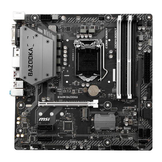
  • Page 88: Vue D' Ensemble Des Composants

    Vue d’ ensemble des composants Socket processeur CPU_PWR1 DIMMA1 DIMMA2 CPU_FAN1 DIMMB1 DIMMB2 SYS_FAN2 ATX_PWR1 SYS_FAN1 JUSB3 JBAT1 PCI_E1 SATA▼1▲2 M2_1 SATA4 PCI_E2 SATA3 JRGB1 PCI_E3 JTBT1 JFP1 SATA5 JAUD1 SATA6 JCOM1 JCI1 JLPT1 JFP2 JTPM1 JUSB2 JUSB1 Vue d’ ensemble des composants...
  • Page 89: Socket Processeur

    électrique. Veuillez garder le capot de protection du processeur après l’ installation du processeur. Selon les exigences de RMA (Return Merchandise Authorization), MSI n’ acceptera pas les cartes mère dont le capot de protection aura été retiré.
  • Page 90: Slots Dimm

    Slots DIMM DIMMA1 DIMMB1 Canal A Canal B DIMMA2 DIMMB2 Installation recommandée de module mémoire DIMMB2 DIMMB2 DIMMB1 DIMMA2 DIMMA2 DIMMA2 DIMMA1 Important Veillez à toujours insérer un module de mémoire dans l’ emplacement DIMMA2 en premier. Du fait des ressources utilisées par le chipset, la capacité de mémoire disponible est un peu moins élevée que celle installée.
  • Page 91: Pci_E1~3 : Slots D' Extension Pcie

    Important Si vous installez une carte graphique lourde, il vous faut utiliser un outil comme la barre de support MSI Gaming Series pour supporter son poids et pour éviter la déformation du slot. Veillez à toujours mettre l’ ordinateur hors tension et à débrancher le cordon d’...
  • Page 92: M2_1 : Slot M.2 (Touche M)

    M2_1 : Slot M.2 (Touche M) Important La technologie Intel RST supporte seulement un SSD ® PCIe M.2 avec une mémoire ROM UEFI et non avec une mémoire ROM Legacy. Vidéo de démonstration Référez-vous à la vidéo d’ instruction sur l’...
  • Page 93: Jfp1, Jfp2 : Connecteurs De Panneau Avant

    JFP1, JFP2 : Connecteurs de panneau avant Ces connecteurs se lient aux interrupteurs et indicateurs LED du panneau avant. JFP1 HDD LED + Power LED + HDD LED - Power LED - Reset Switch Power Switch Reset Switch Power Switch Reserved No Pin Speaker -...
  • Page 94: Jusb1, Jusb2 : Connecteurs Usb 2.0

    Notez que les broches VCC et Terre doivent être branchées correctement afin d’ éviter tout dommage sur la carte mère. Pour recharger votre iPad, iPhone et iPod par l’ intermédiaire d’ un port USB, veuillez installer l’ utilitaire MSI SUPER CHARGER. ®...
  • Page 95: Jcom1 : Connecteur De Port Série

    JCOM1 : Connecteur de port série Ce connecteur vous permet de relier un port série en option. SOUT Ground No Pin JAUD1 : Connecteur audio avant Ce connecteur se lie aux jacks audio du panneau avant. MIC L Ground MIC R Head Phone R MIC Detection SENSE_SEND...
  • Page 96: Cpu_Fan1, Sys_Fan1~2 : Connecteurs Pour Ventilateurs

    CPU_FAN1, SYS_FAN1~2 : Connecteurs pour ventilateurs Les connecteurs pour ventilateurs peuvent être utilisés en mode PWM (Pulse Width Modulation) et en mode DC. En mode PWM, les connecteurs fournissent une sortie de 12V constante et ajustent la vitesse des ventilateurs avec un signal de contrôle de vitesse.
  • Page 97: Jci1 : Connecteur Intrusion Châssis

    JCI1 : Connecteur intrusion châssis Ce connecteur est relié à un câble d’ interrupteur intrusion châssis. Normal Commencer l’ activité intrusion châssis (défaut) Utilisation du détecteur d’ intrusion châssis 1. Reliez le connecteur JCI1 à l’ interrupteur ou au capteur d’ intrusion châssis situé sur le boîtier du PC.
  • Page 98: Jtpm1 : Connecteur De Module Tpm

    JTPM1 : Connecteur de module TPM Ce connecteur est relié à un module TPM (Trusted Platform Module). Veuillez vous référer au manuel du module TPM pour plus d’ informations. LPC Clock 3V Standby power LPC Reset 3.3V Power LPC address & data pin0 Serial IRQ LPC address &...
  • Page 99: Jrgb1 : Connecteur Led Rgb

    Avant d’ installer ou de retirer le ruban LED, veillez à toujours éteindre l’ alimentation et à débrancher le câble d’ alimentation de la prise électrique. Veuillez utiliser un logiciel MSI dédié pour contrôler le ruban d’ extension LED. EZ Debug LED Ces LEDs indiquent l’...
  • Page 100: Configuration Du Bios

    Menu, F11 to enter Boot Menu” sur l’ écran, veuillez appuyer sur la touche Suppr. y Quand l’ ordinateur est déjà en marche, vous pouvez utiliser l’ application MSI FAST BOOT. Cliquez sur le bouton GO2BIOS puis sur OK. Le système redémarre et entre dans l’...
  • Page 101: Réinitialiser Le Bios

    Avant la mise à jour : Veuillez télécharger la dernière version de BIOS compatible à votre carte mère sur le site MSI. Ensuite, veuillez sauvegarder le nouveau BIOS sur le lecteur flash USB. Mettre le BIOS à jour : 1. Connectez le lecteur Flash USB contenant le profil à l’ ordinateur.
  • Page 102: Ez Mode (Mode Simplifié)

    EZ Mode (mode simplifié) Le mode EZ vous fournit les informations basiques du système et vous permet de configurer les réglages de base. Si vous souhaitez configurer les réglages du BIOS, veuillez utiliser le mode Advanced en appuyant sur le switch Setup Mode (Interrupteur de modes de réglages) ou la touche de fonction F7.
  • Page 103 y Ecran d’ informations - cliquez sur les boutons CPU (Processeur), Memory (Mémoire), Storage (Stockage), Fan Info (Info ventilateurs) et Help (Aide) à gauche de la fenêtre pour obtenir les informations respectives. y Boutons de fonction - en cliquant sur leur bouton respectif, vous pourrez activer les fonctions LAN Option ROM, M.2/ Optane Genie, HD audio controller, AHCI, RAID, CPU Fan Fail Warning Control et BIOS Log Review.
  • Page 104: Advanced Mode (Mode Avancé)

    Advanced Mode (mode avancé) Appuyez sur le Setup Mode switch (interrupteur de modes de réglages) ou sur la touche de fonction F7 pour commuter entre le mode simplifié et le mode avancé. Interrupteur de Capture Interrupteur XMP Recherche modes de réglages d’...
  • Page 105: Oc Menu (Menu Overclocking)

    OC Menu (menu overclocking) Ce menu est destiné aux utilisateurs avancés souhaitant overclocker leur carte mère. Important L’ overclocking manuel du PC n’ est recommandé que pour les utilisateurs avancés. L’ overclocking n’ est pas garanti et une mauvaise manipulation peut rendre nulle votre garantie et sévèrement endommager votre matériel.
  • Page 106 f CPU Ratio Offset When Running AVX [Auto] Définit une valeur de décalage pour réduire le ratio du coeur CPU. Cela est utile pour la dissipation de chaleur lors de l’ exécution du jeu d’ instruction AVX. Mis en Auto, le BIOS configure ce réglages automatiquement. Ce menu apparaît lorsque le processeur installé...
  • Page 107 f DRAM Frequency [Auto] Définit la fréquence de la mémoire. Veuillez noter que les résultats de l’ overclocking ne sont pas garantis. f Adjusted DRAM Frequency Affiche la fréquence ajustée de la mémoire. Fonctionne en lecture seule. f Memory Try It ! [Disabled] Memory Try It! permet d’...
  • Page 108 f CPU Specifications Appuyez sur la touche Entrée pour accéder au sous-menu. Ce sous-menu affiche les caractéristiques du processeur installé. Vous pouvez également accéder à ce sous- menu à tout moment en appuyant sur la touche [F4]. Fonctionne en lecture seule. fCPU Technology Support Appuyez sur la touche Entrée pour accéder au sous-menu.
  • Page 109 fHardware Prefetcher [Enabled] Active ou désactive le prefetcher matériel (MLC Streamer prefetcher). [Enabled] Permet au prefetcher matériel d’ acquérir automatiquement les données et les instructions dans le cache L2 de la mémoire pour ajuster les performances du processeur. [Disabled] Désactive le prefetcher matériel. fAdjacent Cache Line Prefetch [Enabled] Active ou désactive le prefetcher matériel du processeur (MLC Spatial prefetcher).
  • Page 110 fLong Duration Power Limit (W) [Auto] Définit le niveau d’ alimentation maximum que le TDP (enveloppe thermique) du processeur peut supporter sur une longue période et en mode Turbo Boost. fLong Duration Maintained (s) [Auto] Définit la durée d’ utilisation de la fonction Long Duration Power Limit (W). fShort Duration Power Limit (W) [Auto] Définit le niveau d’...
  • Page 111: Informations Sur Les Logiciels

    ® Installer les pilotes 1. Allumez l’ ordinateur sous Windows ® 2. Insérez le disque MSI Driver Disc dans le lecteur optique. ® 3. L’ outil d’ installation apparaît automatiquement. Il trouvera et listera tous les pilotes dont vous avez besoin.
  • Page 112 NOTE Informations sur les logiciels...
  • Page 113 Содержание Безопасное использование продукции ............2 Технические характеристики ................ 3 Задняя панель портов ввода/ вывода ............8 Таблица состояний индикатора порта LAN ........... 8 Менеджер Realtek HD Audio ................8 Компоненты материнской платы ............... 10 Процессорный сокет ..................11 Слоты DIMM ......................12 PCI_E1~3: Слоты...
  • Page 114: Безопасное Использование Продукции

    Безопасное использование продукции y Компоненты, входящие в комплект поставки могут быть повреждены статическим электричеством. Для успешной сборки компьютера, пожалуйста, следуйте указаниям ниже. y Убедитесь, что все компоненты компьютера подключены должным образом. Ослабленные соединения компонентов могут привести как к сбоям в работе, так и полной неработоспособности компьютера. y Чтобы...
  • Page 115: Технические Характеристики

    * Порт SATA1 будет недоступен при установке модуля M.2 SATA SSD в разъеме M2_1. ** Перед использованием модулей памяти Intel Optane™ убедитесь, что ® драйверы и BIOS были обновлены до последней версии с веб-сайта MSI. Чипсет Intel RAID H370 ®...
  • Page 116: Разъемы Задней Панели

    Продолжение с предыдущей страницы y Контроллер Intel B360/ H370 ® ƒ 6x портов USB 3.1 Gen1 (SuperSpeed USB) (3 порта Type-A & 1 порт Type-C на задней панели, 2 порта доступны через внутренние разъемы USB) ƒ 6x портов USB 2.0 (High-speed USB) (2 порта Type-A на...
  • Page 117 Продолжение с предыдущей страницы y 1x 24-контактный разъем питания ATX y 1x 8-контактный разъем питания ATX 12В y 6x разъемов SATA 6Гб/с y 1x разъем USB 3.1 Gen1 (Поддержка 2-х дополнительных портов USB 3.1 Gen1) y 2x разъема USB 2.0 (Поддержка 4-х дополнительных портов...
  • Page 118 обеспечение y X-BOOST y GAMING APP y SUPER CHARGER y MYSTIC LIGHT y Open Broadcaster Software (OBS) y CPU-Z MSI GAMING y Intel Extreme Tuning Utility ® y Google Chrome™, Google Toolbar, Google Drive y Norton™ Internet Security Solution Продолжение на следующей странице...
  • Page 119: Эксклюзивные Функции

    Продолжение с предыдущей страницы y Аудио ƒ Audio Boost ƒ Voice Boost y Накопитель ƒ Turbo M.2 y Вентирятор ƒ Интеллектуальное управление вентилятором y Индикатор ƒ Mystic Light Extension(RGB) ƒ Mystic light SYNC ƒ EZ DEBUG LED y Защита Эксклюзивные ƒ...
  • Page 120: Задняя Панель Портов Ввода/ Вывода

    Задняя панель портов ввода/ вывода Линейный вход Линейный выход PS/2 мыши USB 3.1 Gen1 Микрофонный вход PS/2 клавиаткры USB 2.0 DVI-D USB 3.1 Gen1 Type-C Таблица состояний индикатора порта LAN Подключение/ Работа Скорость передачи данных индикатора Состояние Описание Состояние Описание Выкл.
  • Page 121 окно с просьбой подтвердить подключенное устройство. Автоматическое всплывающее диалоговое окно При подключении устройства к разъему аудио появится диалоговое окно с просьбой подтвердить подключенное устройство. (H370M BAZOOKA) (B360M BAZOOKA) Каждый разъем соответствует его настройкам по умолчанию, как показано на следующей странице. Задняя панель портов ввода/ вывода...
  • Page 122: Компоненты Материнской Платы

    Компоненты материнской платы Процессорный сокет CPU_PWR1 DIMMA1 DIMMA2 CPU_FAN1 DIMMB1 DIMMB2 SYS_FAN2 ATX_PWR1 SYS_FAN1 JUSB3 JBAT1 PCI_E1 SATA▼1▲2 M2_1 SATA4 PCI_E2 SATA3 JRGB1 PCI_E3 JTBT1 JFP1 SATA5 JAUD1 SATA6 JCOM1 JCI1 JLPT1 JFP2 JTPM1 JUSB2 JUSB1 Компоненты материнской платы...
  • Page 123: Процессорный Сокет

    Перед установкой или заменой процессора, необходимо отключить кабель питания. Пожалуйста, сохраните защитную крышку процессорного сокета после установки процессора. Любые возможные гарантийные случаи, связанные с работой материнской платы, MSI будет рассматривать только, при наличии ® защитной крышки на процессорном сокете. При установке процессора обязательно установите процессорный...
  • Page 124: Слоты Dimm

    Слоты DIMM DIMMA1 DIMMB1 Канал A Канал B DIMMA2 DIMMB2 Рекомендации по установке модулей памяти DIMMB2 DIMMB2 DIMMB1 DIMMA2 DIMMA2 DIMMA2 DIMMA1 Внимание! Всегда устанавливайте модуль памяти сначала в слот DIMMA2. В связи со спецификой использования ресурсов чипсета, доступный объем памяти...
  • Page 125: Pci_E1~3: Слоты Расширения Pcie

    PCI_E3: PCIe 3.0 x1 (линии PCH) Внимание! При установке массивной видеокарты, необходимо использовать такой инструмент, как MSI Gaming Series Graphics Card Bolster для поддержки веса графической карты и во избежание деформации слота. Перед установкой или извлечением плат расширения убедитесь, что...
  • Page 126: M2_1: Разъем M.2 (Ключ M)

    M2_1: Разъем M.2 (Ключ M) Внимание! RST только поддерживает PCIe M.2 SSD с UEFI Intel ® ROM, а не с Legacy ROM. Видео Инструкция Смотрите видео, чтобы узнать как установить M.2 SSD. http://youtu.be/JCTFABytrYA Установка M.2 SSD 1. Выкрутите стойку для крепления M.2 модуля...
  • Page 127: Jfp1, Jfp2: Разъемы Передней Панели

    JFP1, JFP2: Разъемы передней панели Эти разъемы служат для подключения кнопок и светодиодных индикаторов, расположенных на передней панели. JFP1 HDD LED + Power LED + HDD LED - Power LED - Reset Switch Power Switch Reset Switch Power Switch Reserved No Pin Speaker - Buzzer +...
  • Page 128: Jusb1, Jusb2: Разъемы Usb 2.0

    Внимание! Помните, что во избежание повреждений, необходимо правильно подключать контакты VCC и земли. Для того, чтобы зарядить ваш iPad, iPhone и iPod через порты USB, пожалуйста, установите утилиту MSI SUPER CHARGER. ® JUSB3: Разъем USB 3.1 Gen1 Данный разъем предназначен для подключения портов USB 3.1 Gen1 на...
  • Page 129: Jcom1: Разъем Последовательного Порта

    JCOM1: Разъем последовательного порта Данный разъем позволяет подключить последовательный порт, размещенный на внешнем брекете. SOUT Ground No Pin JAUD1: Разъем аудио передней панели Данный разъем предназначен для подключения аудиоразъемов передней панели. MIC L Ground MIC R Head Phone R MIC Detection SENSE_SEND No Pin Head Phone L...
  • Page 130: Cpu_Fan1, Sys_Fan1~2: Разъемы Вентиляторов

    CPU_FAN1, SYS_FAN1~2: Разъемы вентиляторов Разъемы вентиляторов можно разделить на два типа: с PWM (PulseWidth Modulation) управлением и управлением постоянным током. Разъемы вентиляторов с PWM управлением имеют контакт с постоянным напряжением 12В, а также контакт с сигналом управления скоростью вращения. Управление скоростью...
  • Page 131: Jci1: Разъем Датчика Открытия Корпуса

    JCI1: Разъем датчика открытия корпуса К этому разъему подключается кабель от датчика открытия корпуса. Нормально Разрешить запись по событию (По умолчанию) открытия корпуса Использование датчика открытия корпуса 1. Подключите подключите датчик открытия корпуса к разъему JCI1. 2. Закройте крышку корпуса. 3.
  • Page 132: Jtpm1: Разъем Модуля Tpm

    JTPM1: Разъем модуля TPM Данный разъем используется для подключения модуля ТРМ (Trusted Platform Module). Дополнительные сведения см. в описании модуля ТРМ. LPC Clock 3V Standby power LPC Reset 3.3V Power LPC address & data pin0 Serial IRQ LPC address & data pin1 5V Power LPC address &...
  • Page 133: Jrgb1: Разъем Rgb Led

    Обратите внимание, что длина лент должна быть не более 2 метров, иначе яркость свечения будет падать. Перед установкой или заменой светодиодных лент RGB, необходимо полностью обесточить систему и отключить кабель питания. Используйте утилиту MSI для управления удлинительными ® светодиодными лентами.
  • Page 134: Настройка Bios

    Нажмите клавишу Delete, когда появляется сообщение на экране Press DEL key to enter Setup Menu, F11 to enter Boot Menu во время загрузки. y При помощи приложения MSI FAST BOOT. Нажмите на кнопку GO2BIOS и выберите ОК. Система перезагрузится и автоматически войдет в настройки...
  • Page 135: Сброс Bios

    обратитесь к разделу “Джампер очистки данных CMOS” . Обновление BIOS Обновление BIOS при помощи M-FLASH Подготовительные операции: Пожалуйста, скачайте последнюю версию файла BIOS с сайта MSI, который соответствует вашей модели материнской платы. Сохраните файл BIOS на флэш-диске USB. Обновление BIOS: 1.
  • Page 136: Режим Ez

    Режим EZ Режим EZ предоставляет основную информацию о системе и позволяет выполнить основные операции по настройке. Для настройки расширенных функций BIOS, пожалуйста, войдите в Расширенный режим, путем нажатия Переключатель режимов установки или при помощи функциональной клавиши F7. Переключатель Переключатель XMP режимов...
  • Page 137 y Приоритет загрузочных устройств - вы можете переместить инонку устройства для изменения приоритета загрузки. Приоритет загрузки устанавливается слева направо, от высокого к низкому. y Экран просмотра информации - нажмите на кнопку CPU, Memory, Storage, Fan Info и Help в левой части экрана для отображения соответствующей информации.
  • Page 138: Режим Разгона

    Режим разгона Нажмите переключатель режимов установки или функциональную клавишу F7 для переключения между режимами EZ и разгона в настройках BIOS. Переключатель Переключатель XMP Скриншот Поиск режимов установки Язык Информация о системе Приоритет загрузочных устройств Выбор меню Выбор меню BIOS BIOS Экран...
  • Page 139: Меню Oc

    Меню OC Данное меню предназначено для опытных пользователей и предоставляет возможности для «разгона» системы. Внимание! Разгонять ПК вручную рекомендуется только опытным пользователям. Производитель не гарантирует успешность разгона. Неправильное выполнение разгона может привести к аннулированию гарантии и серьезному повреждению оборудования. f OC Explore Mode [Normal] Включение...
  • Page 140 f Core X X of X xxxx MHz [Auto]* Позволяет устанавливать множители процессора для различных активных ядер. Данный пункт появляется только при установлении CPU Ratio Apply Mode в режим Per Core. f CPU Ratio Offset When Running AVX [Auto] Установка значения смещения для снижения коэффициента ядра процессора.
  • Page 141 f DRAM Reference Clock [Auto]* Установка референсной частоты DRAM. Диапазон допустимых значений зависит от установленного процессора. Этот пункт доступен, если установлен соответсвующий процессор. f DRAM Frequency [Auto] Установка частоты памяти DRAM. Обратите внимание, что возможность успешного разгона не гарантируется. f Adjusted DRAM Frequency Показывает...
  • Page 142 f DRAM Voltages control [Auto] Эти параметры позволяют вам задать напряжения, связанные с памятью. При установке в Auto, BIOS установит напряжения автоматически. Вы также можете настроить напряжения вручную. f CPU Memory Changed Detect [Enabled]* Включение или выключение предупреждающих сообщений при загрузке системы, когда...
  • Page 143 fLimit CPUID Maximum [Disabled] Включение или выключение расширенных значений CPUID. BIOS будет ограничивать максимальное входное значение [Enabled] CPUID для обхода проблемы загрузки в устаревших операционных системах, не поддерживающих процессор с расширенными значениями CPUID. Используйте фактическое максимальное входное значение [Disabled] CPUID. fIntel Virtualization Tech [Enabled] Включение...
  • Page 144 fIntel C-State [Auto] Включение или выключение Intel C-state. C-state - это технология управления питанием процессора, определяемая ACPI. Параметр будет настроен автоматически с помощью BIOS. [Auto] Определяет состояние простоя системы и значительно [Enabled] сокращает энергопотребление процессором. Выключение функции. [Disabled] fC1E Support [Disabled] Включение...
  • Page 145: Описание Программного Обеспечения

    Описание программного обеспечения Cкачайте и обновите последние утилиты и драйверы с сайта: www.msi.com Установка Windows ® 1. Включите компьютер. 2. Вставьте диск Windows 10 в привод для оптических дисков. ® 3. Нажмите кнопку Restart на корпусе компьютера. 4. Нажмите клавишу F11 во время POST (Power-On Self Test) компьютера, чтобы...
  • Page 146 Примечание Описание программного обеспечения...
  • Page 147: Regulatory Notices

    The point of contact for regulatory matters is MSI, recycling and disposing of their end-of-life products. MSI-NL Eindhoven 5706 5692 ER Son. y Visit the MSI website and locate a nearby distributor B급 기기 (가정용 방송통신기자재) for further recycling information.
  • Page 148 MSI will comply with the product take entregar a una empresa autorizada para la recogida de back requirements at the end of life of MSI-branded estos residuos.
  • Page 149 MSI si adeguerà a tale Direttiva ritirando tutti i prodotti marchiati MSI che sono stati venduti all’interno dell’Unione Europea alla fine del loro ciclo di vita.
  • Page 150 Version 1.0, 2018/02, First release. owners. No warranty as to accuracy or completeness is expressed or implied. MSI reserves the right to make changes to this document without prior notice. Technical Support If a problem arises with your system and no solution can be obtained from the user guide, please contact your place of purchase or local distributor.

Ce manuel est également adapté pour:

H370m bazooka

Table des Matières