Table des Matières

Publicité

Les langues disponibles
  • FR

Les langues disponibles

Liens rapides

Installation and operating instructions
Notice de montage et de mise en service
Instrucciones de montaje y uso
EA-Nr.:
FAR-Best.-Nr.:
EA-Nr.:
FAR-Best.-Nr.:
Franke Aquarotter GmbH, Germany
ZMI_001_2030018721-PR3O0020_#SALL_#AQU_#V1.fm/05.02.15
7612982216572
2030018721
PR3O0020
7612982079092
2000101164
AQUA104
Istruzioni per il montaggio e l'uso
Montage- en bedrijfsinstructies
DE
EN
FR
ES
IT
NL

Publicité

Table des Matières
loading

Sommaire des Matières pour Franke PR3O0020

  • Page 1 Installation and operating instructions Istruzioni per il montaggio e l’uso Notice de montage et de mise en service Montage- en bedrijfsinstructies Instrucciones de montaje y uso EA-Nr.: 7612982216572 FAR-Best.-Nr.: 2030018721 PR3O0020 EA-Nr.: 7612982079092 FAR-Best.-Nr.: 2000101164 AQUA104 Franke Aquarotter GmbH, Germany ZMI_001_2030018721-PR3O0020_#SALL_#AQU_#V1.fm/05.02.15...
  • Page 2 ..................3 Please refer to the graphics in the German Installation and Operating Instructions..................18 Les graphiques sont disponibles dans la notice de montage et de mise en service allemande..................34 Por favor, consulte los gráficos en las instrucciones alemanas de montaje y uso.
  • Page 3: Table Des Matières

    0English PROTRONIC - A3000 open wash basin fitting with thermostat, 24 V DC PR3O0020 ....Finished installation kit AQUA104 ....Basic installation kit Please refer to the graphics in the German installation and operating instructions. Table of contents Abbreviations and units ....... . 4 Key .
  • Page 4: Abbreviations And Units

    Earth leakage circuit breaker SELV Safety extra low voltage EA-Nr. European article number FAR-Best.-Nr. Franke Aquarotter order number Conversion 1 mm = 0.03937 inches 1 inch = 25.4 mm All length specifications in the graphics are in mm. Warning! Failure to observe can result in bodily injury or even death.
  • Page 5: Application

    Application PROTRONIC - A3000 open, non-contact, opto-electronically controlled DN 15 thermostat battery for wall-mounted wash basins, with the option of external control, such as valve settings and communication via ECC function controller. For connection to hot and cold water supply. The flow time can be set in one-second steps.
  • Page 6: Scope Of Delivery

    Scope of delivery Basic installation kit Quantity Name Wall unit with lockable water quantity regulators and flush connector Electrical T-distributor with protective cap Wall protection Installation and operating instructions Installation kit Quantity Name Cover plate with sensor module Electronic module M3 Function block with thermostat mixer valve Connection extension Rosettes...
  • Page 7 Caution! The wall-mounting plate must be attached, as otherwise the outlet cannot be fixed with the necessary stability. ☞ If an installation frame is used, it should be ensured that the wall-mounting plate can be attached. 10.1 Create a wall recess. Choose the depth of the wall recess so that the front edge of the wall mounting box (d) is flush with the front edge of the masonry (in front of the tiles).
  • Page 8: Installation Of Finished Installation Kit

    ☞ The various wire guides are marked with numbers 1 to 4. A: Union nut B: FAR-Best.-Nr. 2000104272 brown FAR-Best.-Nr. 2000104274 FAR-Best.-Nr. 2000100801 white white FAR-Best.-Nr. 2000100852 blue blue black black 10.15 Push the wires (o) into the wire guides (p) according to their colours. 10.16 Cut off the projecting wire ends flush, i.e.
  • Page 9 Caution! Use an open-ended wrench to hold the water quantity regulators (d) in position while turning the cap nuts (c). 11.6 Remove the T-type flush connector (e) and any seals that are present. 11.7 Install the function block (f) and the connection extension (g) with new seals. 11.8 Use an open-ended wrench to fasten the connection piece (h) until it seals to G½B level.
  • Page 10: Function

    12. Function 12.1 Approach the fitting. • The water will flow. 12.2 Move away from the fitting. • The water flow will stop automatically. Temperature selection 13. Adjusting the range The range can be adjusted using an ECC2 function controller via the web application. 14.
  • Page 11: Thermal Disinfection -Automatic

    15.1 Turn the temperature selector (a) to the hot water stop. 15.2 Use the Allen key to push in the stop. 15.3 Turn the temperature selector (a) in an anti-clockwise direction up to the stop. 15.4 Trigger the fitting. 15.5 Measure the hot water temperature. 15.6 If the hot water temperature is >...
  • Page 12: Setting The Scald Protector

    17. Setting the scald protector Warning! If the hot water supply temperature is above 45°C, the scald protector should be set. Failure to observe this instruction can result in injuries due to scalding. ☞ The scald protector (hot water stop) has been set to 38°C at the factory. Set the system-specific parameters before use.
  • Page 13: Replacing The Filters

    18.2 Release the screw (c) and the disk. 18.3 Remove the temperature selector (b). 18.4 Remove the rosette (a). 18.5 Undo the grub screw (f) with an Allen key. 18.6 Remove the headpiece (g) from the wall bracket. 18.7 Remove the rosette (e). 18.8 Remove the safety screws (k) and their locknuts (h) from the cover plate.
  • Page 14: Replace The Thermal Element

    21. Replace the thermal element Warning! Set the scald protection after installing the fitting or removing the thermal element. Failure to observe this instruction can result in injuries due to scalding. 21.1 Remove the cover plate (see Chapter 18.). 21.2 Remove the screw (b) Caution! Apply the pliers to the area with the largest diameter (a) behind the small sprocket wheel.
  • Page 15: Replace The Aerator

    23. Replace the aerator 23.1 Use the special wrench (e) to loosen the entire aerator. 23.2 Remove the entire aerator from the headpiece (a). 23.3 Remove the seal (b). 23.4 Remove the casing (c). 23.5 Replace the aerator (d). 23.6 Reassemble in reverse order. 24.
  • Page 16: Troubleshooting

    25. Troubleshooting Fault Cause Remedy ➯ Restore it Water does not flow – Water supply interrupted ➯ Open it – Water volume regulator closed ➯ Restore it – Power supply interrupted ➯ Replace it – Dirty filters ➯ Replace it –...
  • Page 17: Spare Parts

    26. Spare parts Description Order No. Description Order No. 1 Temperature selector... 2030003254 Lockable water volume regulator..2000105782 1a Cover platelet ....2030003258 M3* electronic module .
  • Page 18 0Français Robinetterie de lavabo PROTRONIC - A3000 open avec thermostat, 24 V DC PR3O0020 ....Kit de montage final AQUA104 ....Kit de montage brut Les graphiques figurent dans la notice de montage et de mise en service allemande. Table des matières Abréviations et unités .
  • Page 19: Abréviations Et Unités

    Safety Extra Low Voltage, très basse tension de sécurité EA-Nr. Numéro d'article européen FAR-Best.-Nr. Référence de commande Franke Aquarotter Conversion 1 mm = 0,03937 pouce 1 pouce = 25,4 mm Sur les graphiques, toutes les longueurs sont exprimées en mm.
  • Page 20: Remarques Importantes

    Remarques importantes • Seul un spécialiste est habilité à effectuer le montage, la mise en service et l'entretien de l'installation, et ceci tout en veillant à ce que ces opérations soient réalisées conformément aux instructions fournies, aux prescriptions légales et aux règles techniques en usage.
  • Page 21: Caractéristiques Techniques

    Caractéristiques techniques Pression dynamique minimale : 1,0 bar Pression dynamique recommandée : 1–5 bar Pression de service maximale : 10 bar Débit théorique : 0,07 l/s 0,07 l/s Débit volumétrique : 0,10 l/s pour une pression dynamique de 3 bar Durée d'écoulement à...
  • Page 22: Dimensions

    Dimensions Exemple d'installation 10. Montage du kit de montage brut Avertissement ! • Ne faire fonctionner le produit qu'à très basse tension de sécurité (SELV). Les composants ne doivent pas être mis à la terre. • Placer l'alimentation en tension (non fournie, voir Accessoires, Chapitre 26) hors de la zone humide dans une autre pièce.
  • Page 23 10.10 Installer les régulateurs du débit d'eau (f) de façon à ce que la vis de fermeture (g) et l'élément de commande (h) soient accessibles. Au besoin, desserrer l'élément de nettoyage. 10.11 Poser le câble système (i) dans la gaine et le connecter de robinetterie en robinetterie. ☞...
  • Page 24: Montage Du Kit De Montage Final

    11. Montage du kit de montage final Avertissement ! Ne faire fonctionner la robinetterie qu'avec des clapets de non-retour et les filtres prévus. Le non-respect de cette consigne peut entraîner une augmentation de la concen- tration en germes dans l'eau potable et générer un risque pour la santé, voire un danger de mort.
  • Page 25: Fonctionnement

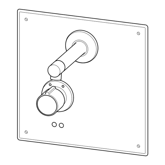
    11.18 Visser la plaque de protection (r) avec les vis de sécurité (o). 11.19 Retirer les vis bloquées (p). 11.20 Insérer la rosace (s). 11.21 Glisser l'embout (u) sur le bras mural. 11.22 Visser à fond la tige filetée (v) à l'aide d'une clé Allen. 11.23 Faire glisser la rosace (t) de façon à...
  • Page 26: Désinfection Thermique -Manuelle

    15. Désinfection thermique -manuelle- Ce type de robinetterie de douche permet d'effectuer une désinfection thermique afin de réduire le risque d'infection causée par les légionelles ! Le déclenchement de la désinfection thermique s'effectue en tournant le thermostat à fond. Avertissement ! Pendant la durée de la désinfection thermique, il convient de prendre des mesures de protection personnelle (protection contre les brûlures), par exemple barrer l'accès aux sanitaires.
  • Page 27: Désinfection Thermique -Automatique

    16. Désinfection thermique -automatique- Attention ! Respecter les indications figurant dans l'aide à la conception Désinfection thermique (01805618). Accessoires requis Contrôleur de fonction ECC2 (60 W) avec connexion Ethernet ... . . 2000108123 Cartouche d'électrovanne de dérivation .
  • Page 28: Maintenance Et Entretien

    18. Maintenance et entretien En fonction de la qualité de l'eau ainsi que des conditions et des dispositions locales, il convient de contrôler et d'entretenir la robinetterie à intervalles réguliers. L'entretien doit porter sur les composants suivants : • gazéificateur (voir Chapitre 23.) •...
  • Page 29: Remplacement Des Filtres

    19. Remplacement des filtres Filtres des régulateurs de débit d'eau 19.1 Retirer la plaque de protection (voir Chapitre 18.). 19.2 Desserrer les vis de fermeture (a) sur les régulateurs de débit d'eau. 19.3 Remplacer les filtres (b). ☞ Important ! Veiller à...
  • Page 30: Remplacer Le Thermocouple

    21. Remplacer le thermocouple Avertissement ! Régler la protection contre les brûlures après avoir monté la robinetterie ou démonté le thermocouple. Le non-respect de cette consigne peut entraîner des brûlures. 21.1 Retirer la plaque de protection (voir Chapitre 18.). 21.2 Défaire la vis (b) Attention ! Placer la pince au niveau du plus grand diamètre (a) derrière la petite couronne dentée.
  • Page 31: Remplacer Le Gazéificateur

    23. Remplacer le gazéificateur 23.1 Détacher le gazéificateur complet avec la clé spéciale (e). 23.2 Retirer le gazéificateur complet de l'embout (a). 23.3 Retirer le joint (b). 23.4 Retirer la douille (c). 23.5 Remplacer le gazéificateur (d). 23.6 L'assemblage s'effectue dans l'ordre inverse. 24.
  • Page 32: Dépannage

    25. Dépannage Dysfonctionnement Cause Solution ➯ Rétablir L'eau ne coule pas – Alimentation en eau interrompue ➯ Ouvrir – Régulateur du débit d'eau fermé ➯ Rétablir – Alimentation en tension coupée ➯ Remplacer – Filtres encrassés ➯ Remplacer – Clapet de non-retour défectueux ➯...
  • Page 33: Pièces De Rechange

    26. Pièces de rechange désignation num. de cde désignation num. de cde 1 Sélecteur de température ..2030003254 Régulateur du débit d'eau verrouillable ....2000105782 1a Plaquette de protection .
  • Page 34 0Español Grifería para lavabo PROTRONIC - A3000 open con termostato, 24 V CC PR3O0020 ....Juego de instalación premontado AQUA104 ....Juego para obra bruta Puede consultar los gráficos en las instrucciones de instalación y funcionamiento alemanas. Índice Abreviaturas y unidades ....... . 35 Aclaración de símbolos .
  • Page 35: Abreviaturas Y Unidades

    Safety Extra Low Voltage, baja tensión de protección EA-Nr. Número de artículo europeo FAR-Best.-Nr. Número de pedido Franke Aquarotter Conversión 1 mm = 0,03937 pulgadas 1 pulgada = 25,4 mm Todos los datos de longitudes de los gráficos se indican en mm.
  • Page 36: Aplicación

    Aplicación Batería de termostato DN 15 con control optoelectrónico sin contacto PROTRONIC - A3000 open para montaje en pared para instalaciones de lavabo con posibilidad de control externo, como ajuste de grifería y comunicación mediante el controlador de función ECC. Para conectar al agua fría y caliente. Tiempo de flujo ajustable con precisión al segundo.
  • Page 37: Volumen De Suministro

    Volumen de suministro Juego para obra bruta Unidades Denominación Caja de montaje en pared con pieza de enjuague y reguladores del flujo de agua bloqueables Distribuidor eléctrico en T con tapa protectora Protección para obra Instrucciones de instalación y funcionamiento Juego de instalación premontado Unidades Denominación...
  • Page 38 ¡Atención! Es preciso fijar la placa de sujeción mural, ya que, de lo contrario, no se puede colocar la salida con la estabilidad necesaria. ☞ En caso de utilizar estructuras de instalación debe proveerse una posibilidad de fijación de la placa de sujeción mural. 10.1 Hacer un hueco en la pared.
  • Page 39: Montaje Del Juego De Instalación Premontado

    10.14 Encajar la tuerca de racor (n) hasta el tope en el cable del sistema (m). ☞ Las guías de hilo están marcadas con los números de 1 a 4. A: Tuerca de racor B: FAR-Best.-Nr. 2000104272 marrón rojo FAR-Best.-Nr. 2000104274 FAR-Best.-Nr.
  • Page 40 11.4 Introducir los filtros (b). 11.5 Enroscar los tornillos de cierre (a). ¡Atención! Al girar las tuercas de racor (c) con una llave de boca, mantener en su posición los reguladores del flujo de agua (d). 11.6 Retirar la pieza de enjuague en T (e) y las juntas disponibles. 11.7 Montar el bloque funcional (f) y la prolongación de conexión (g) con juntas nuevas.
  • Page 41: Funcionamiento

    11.26 Colocar el anillo de tope (l) de tal modo que la marca (z) del anillo de tope quede centrada por debajo de las marcas (y) de la roseta. ☞ ¡Importante! Colocar el mango selector de temperatura (m) de tal modo que el tope quede a ras con el resalte del anillo de tope.
  • Page 42: Desinfección Térmica -Manual

    15. Desinfección térmica -manual- ¡Esta grifería de ducha ofrece la posibilidad de desinfección térmica para reducir el riesgo de infección por legionela! La activación de la desinfección térmica se produce mediante un sobregiro del termostato. ¡Advertencia! Durante la desinfección térmica deben tomarse medidas de protección individual (protección para evitar la escaldadura), p.
  • Page 43: Desinfección Térmica -Automática

    16. Desinfección térmica -automática- ¡Atención! Observar los datos que figuran en la Guía de planificación de la desinfección térmica (01805618). Accesorios necesarios Controlador de función ECC2 (60 W) con conexión Ethernet ....2000108123 Cartucho de la válvula magnética de derivación .
  • Page 44: Mantenimiento Y Cuidados

    18. Mantenimiento y cuidados En función de la calidad del agua, las condiciones locales y la legislación vigente, realizar las inspecciones y el mantenimiento de la grifería a intervalos regulares. Realizar el mantenimiento de los siguientes componentes: • Aireador (véase el capítulo 23.) •...
  • Page 45: Cambio Del Cartucho De La Válvula Magnética

    20. Cambio del cartucho de la válvula magnética 20.1 Retirar la plaquita cobertora (véase el capítulo 18.). 20.2 Separar la conexión por cable entre el cartucho de la válvula electromagnética y el módulo electrónico. 20.3 Desenroscar los tornillos (a). 20.4 Extraer el cartucho de la válvula electromagnética (b) y sustituirlo. 20.5 Para volver a montarlo, seguir los pasos en el orden inverso.
  • Page 46: Cambio Del Aireador

    23. Cambio del aireador 23.1 Soltar el aireador al completo con la llave especial (e). 23.2 Retirar el aireador al completo de la pieza del cabezal (a). 23.3 Retirar la junta (b). 23.4 Retirar el casquillo (c). 23.5 Cambiar el aireador (d). 23.6 Para volver a montarlo, seguir los pasos en el orden inverso.
  • Page 47: Subsanación De Averías

    25. Subsanación de averías Avería Causa Subsanación ➯ Restablecer El agua no fluye – Interrupción del suministro de agua ➯ Abrir – Regulador del flujo de agua cerrado ➯ Restablecer – Interrupción de la alimentación de tensión ➯ Cambiar – Filtros sucios ➯...
  • Page 48: Piezas De Repuesto

    26. Piezas de repuesto Denominación Núm. pedido Denominación Núm. pedido 1 Mango selector de temperatura . . 2030003254 Regulador del flujo de agua bloqueable ....2000105782 1a Plaquita cobertora .
  • Page 49 0Italiano Rubinetteria per zona lavabo PROTRONIC - A3000 open con termostato, 24 V CC PR3O0020 ....kit di installazione completo AQUA104 ....set di montaggio a incasso Per le figure consultare le istruzioni di montaggio e uso in tedesco. Indice Abbreviazioni e unità...
  • Page 50: Abbreviazioni E Unità

    SELV Safety Extra Low Voltage, bassissima tensione di sicurezza EA-Nr. Codice articolo europeo FAR-Best.-Nr. Codice articolo Franke-Aquarotter Conversione 1 mm = 0,03937°pollici 1°pollice = 25,4 mm Tutte le indicazioni di lunghezza nelle figure sono in mm. Spiegazione dei simboli Avvertenza! La mancata osservanza può...
  • Page 51: Impiego

    Impiego Miscelatore termostatico senza contatto ad azionamento opto-elettronico PROTRONIC - A3000 open DN 15 da montare a incasso per impianti di lavaggio, con possibilità di comando esterno, come regolazione apparecchio e comunicazione mediante controller ECC. Da collegare all'acqua calda e fredda. Durata del flusso regolabile al secondo.
  • Page 52: Dotazione Della Fornitura

    Dotazione della fornitura Set di montaggio a incasso Unità Denominazione Cassetta da incasso con connettore di lavaggio e regolatori intercettabili della quantità d'acqua Distributore elettrico a T con cappuccio di prote- zione Blocco di protezione Istruzioni di montaggio e uso Kit di installazione completo Unità...
  • Page 53 Attenzione! La piastra di sostegno a parete deve essere fissata, altrimenti non è possibile applicare l'erogatore con la necessaria stabilità. ☞ Se si usano supporti di installazione, assicurarsi che sia possibile fissare la piastra di sostegno a parete. 10.1 Praticare un'apertura nella parete. La profondità dell'apertura nella parete deve essere tale da consentire che il bordo anteriore della cassetta da incasso (d) venga a trovarsi a raso con il bordo anteriore dell'opera in muratura (prima della piastrellatura).
  • Page 54: Montaggio Del Kit Di Installazione Completo

    ☞ Le guide dei conduttori sono contrassegnate con i numeri da 1 a 4. A: dadi di raccordo B: FAR-Best.-Nr. 2000104272 marrone rosso FAR-Best.-Nr. 2000104274 FAR-Best.-Nr. 2000100801 bianco bianco FAR-Best.-Nr. 2000100852 nero nero 10.15 Innestare i conduttori (o) nelle rispettive guide (p) in base al colore. 10.16 Tagliare le sporgenze dei conduttori a raso, ossia senza prominenza.
  • Page 55 Attenzione! Mentre si ruotano i dadi di raccordo (c) con una chiave fissa tenere fermi i regolatori della quantità d'acqua (d). 11.6 Rimuovere il connettore di lavaggio a T (e) e le guarnizioni presenti. 11.7 Montare il blocco funzionale (f) e la prolunga collegamento (g) con nuove guarni- zioni.
  • Page 56: Funzionamento

    ☞ Importante! Collocare la manopola di selezione della temperatura (m) in modo che la battuta poggi a raso contro l'aletta dell'anello di arresto. 11.27 Spingere la manopola di selezione della temperatura (m) sull'anello di arresto (l). 11.28 Fissare la manopola di selezione della temperatura (m) all'apparecchio con la vite e la rondella.
  • Page 57: Disinfezione Termica -Automatica

    La rubinetteria termostatica è predisposta per l'esecuzione della disinfezione termica mediante rotazione del termostato oltre la battuta. Sbloccando la battuta nascosta della manopola di selezione della temperatura, la rubinetteria termostatica offre la possibilità di disinfettare manualmente (risciacquo con una temperatura dell'acqua di ≥...
  • Page 58: Regolazione Della Protezione Dalle Scottature

    17. Regolazione della protezione dalle scottature Avvertenza! Regolare la protezione dalle scottature quando la temperatura di erogazione dell'acqua calda supera i 45 °C. La mancata osservanza può comportare lesioni dovute a scottature. ☞ La protezione dalle scottature (arresto dell'acqua calda) è preimpostata di fabbrica su 38 °C.
  • Page 59: Sostituzione Dei Filtri

    Rimozione della piastrina di copertura Per alcuni interventi di manutenzione si rende necessario rimuovere la piastrina di copertura. 18.1 Rimuovere la piastrina di copertura (d). 18.2 Allentare la vite (c) e la rondella. 18.3 Estrarre la manopola di selezione della temperatura (b). 18.4 Rimuovere la rosetta (a).
  • Page 60: Sostituzione Del Termoelemento

    21. Sostituzione del termoelemento Avvertenza! Dopo il montaggio dell'apparecchio o lo smontaggio del termoelemento, impostare la protezione dalle scottature. La mancata osservanza può comportare lesioni dovute a scottature. 21.1 Rimuovere la piastrina di copertura (vedere capitolo 18.). 21.2 Svitare la vite (b). Attenzione! Applicare la pinza al diametro più...
  • Page 61: Sostituzione Del Rompigetto

    23. Sostituzione del rompigetto 23.1 Allentare il rompigetto completo con la chiave speciale (e). 23.2 Rimuovere il rompigetto completo dall'elemento di testa (a). 23.3 Rimuovere la guarnizione (b). 23.4 Rimuovere la bussola (c). 23.5 Sostituire il rompigetto (d). 23.6 Il montaggio avviene in sequenza inversa. 24.
  • Page 62: Eliminazione Delle Anomalie

    25. Eliminazione delle anomalie Anomalia Causa Rimedio ➯ Ristabilire L'acqua non scorre – Alimentazione d'acqua interrotta ➯ Aprire – Regolatore della quantità d'acqua chiuso – Alimentazione di tensione interrotta ➯ Ristabilire ➯ Sostituire – Filtri sporchi ➯ Sostituire – Valvola di non ritorno guasta ➯...
  • Page 63: Ricambi

    26. Ricambi Denominazione Cod. Art. Denominazione Cod. Art. 1 Manopola di selezione della Regolatore temperatura ....2030003254 intercettabile della quantità d'acqua ....2000105782 1a Piastrina di copertura .
  • Page 64 0Nederlands PROTRONIC - A3000 open wastafelarmatuur met thermostaat, 24 V DC PR3O0020 ....Kant-en-klare bouwset AQUA104 ....Ruwbouwset De tekeningen kunt u vinden in de Duitstalige montage- en gebruikshandleiding. Inhoudsopgave Afkortingen en eenheden ....... 65 Verklaring van de symbolen .
  • Page 65: Afkortingen En Eenheden

    SELV Safety Extra Low Voltage, zeer lage veiligheids- spanning EA-Nr. Europees artikelnummer FAR-Best.-Nr. Franke-Aquarotter-bestelnummer Omrekening 1 mm = 0,03937 inch 1 inch = 25,4 mm Alle lengtegegevens in tekeningen zijn in mm aangegeven. Verklaring van de symbolen Waarschuwing! Veronachtzaming van de instructie kan levensgevaar of lichamelijk letsel veroor- zaken.
  • Page 66: Toepassing

    Toepassing PROTRONIC - A3000 open contactloos, opto-elektronisch gestuurde thermostaat- kraan DN 15 voor wandinbouw voor wastafels, met mogelijkheid tot externe besturing zoals armatuurinstelling en communicatie via ECC-functiecontroller. Voor aansluiting op warm en koud water. Stromingstijd tot op de seconde instelbaar. Met geïntegreerde magneetklepcartouche, voorziening voor optionele magneetklep- cartouche voor omleiding om een thermische desinfectie te kunnen uitvoeren en mogelijkheid om handmatig een thermische desinfectie uit te voeren.
  • Page 67: Omvang Van De Levering

    Omvang van de levering Ruwbouwset Aantal Omschrijving Wandinbouwdoos met spoelstuk en afsluitbare waterhoeveelheidreguleringen Elektrische T-verdeler met beschermkap Ruwbouwbescherming Montage- en gebruikshandleiding Kant-en-klare bouwset Aantal Omschrijving Afdekplaat met sensormodule Elektronische module M3 Functieblok met thermostatische mengkraan Aansluitverlengstuk Rozetten Uitloop Plastic zakje met zeven en afdichtingen Montage- en gebruikshandleiding Afmetingen Installatievoorbeeld...
  • Page 68 Attentie! De wandsteunplaat moet bevestigd worden, anders kan de uitloop niet met de benodigde stabiliteit worden aangebracht. ☞ Bij gebruik van installatieframes moet een mogelijkheid worden voorzien om de wandsteunplaat te kunnen bevestigen. 10.1 Een uitsparing in de wand maken. De diepte van de uitsparing in de wand zo kiezen dat de voorkant van de wandinbouwbox (d) perfect aansluit op de voorkant van het metselwerk (bij tegels).
  • Page 69: Montage Kant-En-Klare Bouwset

    ☞ De draadgeleidingen zijn gemarkeerd met de cijfers 1 tot 4. A: Wartelmoer B: FAR-Best.-Nr. 2000104272 bruin rood FAR-Best.-Nr. 2000104274 FAR-Best.-Nr. 2000100801 FAR-Best.-Nr. 2000100852 blauw blauw zwart zwart 10.15 Klik de draden (d) met de juiste kleur vast in de draadgeleidingen (e). 10.16 Snij de uitstekende draadeinden glad af, laat deze dus niet uitsteken.
  • Page 70 Attentie! Tijdens het draaien van de wartelmoeren (c) met een steeksleutel de waterhoeveelheidreguleringen (d) op hun positie houden. 11.6 Het T-spoelstuk (e) en de aanwezige afdichtingen verwijderen. 11.7 Het functieblok (f) en het aansluitverlengstuk (g) met nieuwe afdichtingen monteren. 11.8 Het aansluitpijpstuk (h) G½B afdichtend met een steeksleutel inschroeven. 11.9 De wandarm (k) op het aansluitpijpstuk (h) schuiven.
  • Page 71: Werking

    11.27 De keuzegreep voor temperatuur (m) op de aanslagring (l) schuiven. 11.28 De keuzegreep voor temperatuur (m) met de schroef en de schijf op de armatuur vastzetten. 11.29 Het dekplaatje (n) erop drukken. 11.30 Het bereik controleren en zo nodig afstellen (zie hoofdstuk 13.).
  • Page 72: Thermische Desinfectie -Automatisch

    De thermostaatarmatuur is voorzien van een optie om de thermostaat door te draaien en zo een thermische desinfectie uit te voeren. Door de verborgen aanslag aan de keuzegreep voor temperatuur te ontgrendelen, biedt de thermostaatarmatuur de mogelijkheid om een handmatige thermische desinfectie uit te voeren (spoelen met een watertemperatuur van ≥...
  • Page 73: Beveiliging Tegen Brandwonden Instellen

    17. Beveiliging tegen brandwonden instellen Waarschuwing! Als de temperatuur van de warmwatervoorziening meer dan 45 °C bedraagt, stel dan de beveiliging tegen brandwonden in. Veronachtzaming kan lichamelijk letsel door brandwonden veroorzaken. ☞ De beveiliging tegen brandwonden (stop voor heet water) is af fabriek ingesteld op 38 °C.
  • Page 74: Zeven Vervangen

    Afdekplaat weghalen Voor sommige onderhoudswerkzaamheden moet de afdekplaat worden wegge- haald. 18.1 Het dekplaatje (d) verwijderen. 18.2 De schroef (c) en de schijf losdraaien. 18.3 De keuzegreep voor temperatuur (b) lostrekken. 18.4 De rozet (a) verwijderen. 18.5 De schroefdraadpen (f) met een inbussleutel losdraaien. 18.6 Het kopstuk (g) van de wandarm trekken.
  • Page 75: Thermo-Element Vervangen

    21. Thermo-element vervangen Waarschuwing! Stel na montage van de armatuur of demontage van het thermo-element de bevei- liging tegen brandwonden in. Veronachtzaming kan lichamelijk letsel door brandwonden veroorzaken. 21.1 De afdekplaat verwijderen (zie hoofdstuk 18.). 21.2 De schroef (b) uitdraaien Attentie! De tang met grotere diameter (a) achter de kleine tandkrans plaatsen.
  • Page 76: Perlator Vervangen

    23. Perlator vervangen 23.1 De complete perlator met de speciale sleutel (e) losdraaien. 23.2 De complete perlator uit het kopstuk (a) verwijderen. 23.3 De afdichting (b) verwijderen. 23.4 De huls (c) verwijderen. 23.5 De perlator (d) vervangen. 23.6 De montage gebeurt in omgekeerde volgorde. 24.
  • Page 77: Verhelpen Van Storingen

    25. Verhelpen van storingen Storing Oorzaak Remedie ➯ Herstellen Water stroomt niet – Watertoevoer onderbroken ➯ Openen – Waterhoeveelheidregulering gesloten ➯ Herstellen – Stroomvoorziening onderbroken ➯ Vervangen – Zeef verontreinigd ➯ Vervangen – Keerklep defect ➯ Vervangen – Opto-sensor defect ➯...
  • Page 78: Reserveonderdelen

    26. Reserveonderdelen Aanduiding Bestelnr. Aanduiding Bestelnr. 1 Keuzegreep voor temperatuur..2030003254 Afsluitbare waterhoeveelheidregulering . . . 2000105782 1a Dekplaatjes ....2030003258 Elektronische module M3* .
  • Page 79 Notes / Notes / Notas / Annotazioni / Notities...
  • Page 80 +213 (0)21 60 13 60 e: ws-info.de@franke.com e: info@handassagroup.com.tn e: customer@bfi xgroupe.com Franke Caucasus Ltd. Franke Mutfak ve Banyo Sistemleri San. ve PR Kitchen and Washroom Systems Pty Ltd 7, Agladze Street Tic. A.S 83 Bangholme Road Tbilisi, 0154 / Georgia Gebze Organize Sanayi Bölgesi...

Ce manuel est également adapté pour:

Aqua10476129820790927612982216572

Table des Matières