Eaton ATC-300 Mode D'emploi
Masquer les pouces
Voir aussi pour ATC-300:
- Manuel d'utilisation (40 pages) ,
- Manuel d'utilisation et d'entretien (48 pages) ,
- Manuel d'utilisation (56 pages)
Table des Matières
O & M Manual for the EATON ATC-300 Automatic
Transfer Switch Controller
Instruction Booklet
New Information
Description
Introduction . . . . . . . . . . . . . . . . . . . . . . . . . . . . . . . . . . . . . . . . . . . 2
Hardware Description . . . . . . . . . . . . . . . . . . . . . . . . . . . . . . . . . . . . . 7
Status Monitoring and Setpoints . . . . . . . . . . . . . . . . . . . . . . . . . . . . . 11
Typical Function of the ATC-300 Controller . . . . . . . . . . . . . . . . . . . . . . 13
Operation . . . . . . . . . . . . . . . . . . . . . . . . . . . . . . . . . . . . . . . . . . . . . 15
Programming . . . . . . . . . . . . . . . . . . . . . . . . . . . . . . . . . . . . . . . . . . . 19
Troubleshooting and Maintenance . . . . . . . . . . . . . . . . . . . . . . . . . . . . 23
Appendix A: Display Messages for Status and Timers . . . . . . . . . . . . . . . 25
Appendix B: Operational Flowcharts . . . . . . . . . . . . . . . . . . . . . . . . . . . 26
Appendix C: Display Menu Tree . . . . . . . . . . . . . . . . . . . . . . . . . . . . . . 29
Appendix D: Pickup / Dropout Tables . . . . . . . . . . . . . . . . . . . . . . . . . . 35
IB01602001T
For more information visit: www.eatonelectrical.com
Page
Table des Matières

Manuels Connexes pour Eaton ATC-300


Sommaire des Matières pour Eaton ATC-300
-
Page 1: Table Des Matières
Status Monitoring and Setpoints ......11 Typical Function of the ATC-300 Controller ..... . 13 Operation . -
Page 2: Introduction
1. Main contacts to connect and disconnect the load to and contained herein. In no event will EATON be responsible to from the power sources. the purchaser or user in contract, in tort (including negli- gence), strict liability or otherwise for any special, indirect, 2. - Page 3 Store customer/factory established parameters in nonvola- 1.5 Functions/Features/Options tile memory; and The primary function of ATC-300 Controller is to accurately Provide faceplate source status indications. monitor power sources and provide the necessary intelligence to operate an ATS in an appropriate and timely manner. In 1.4 Glossary...
-
Page 4: Standard Features
Test Operators tile memory. Activated feature setpoints are available for Eaton ATSs are provided with a Test Pushbutton that customer adjustment. Any feature not selected and factory simulates a loss of the Source 1 power source as stan- activated cannot be viewed or adjusted. - Page 5 Source 1. tion functions. If the Source 1 power supply fails, then the ATC-300 will begin the sequence of opera- 12D. Source 2 - Source Connected tions necessary to transfer the load circuit to the Source 2 power source.
-
Page 6: Optional Features
(Dropout –2%). A setpoint for user-selectable time 1.5.2.2 Optional Features delay from 10 to 30 seconds is provided. The factory The following is a list of the optional features of the ATC-300 default setpoints are: 5% dropout, 3% pickup, and 30 Controller. -
Page 7: Hardware Description
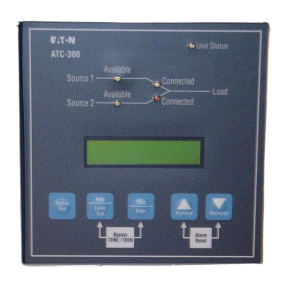
Adjustable Underfrequency: Set and monitor the operating parameters. Dropout: 90-97% of nominal The ATC-300 Controller front panel serves two primary func- Pickup: (Dropout +1Hz) to 99% of nominal tions: output and input. The output function consists of: 26F. All Phase Overfrequency Protection... - Page 8 Unit Status The green Unit Status LED blinks at a rate of once per second while in the ATC-300 Controller is in the “Run” Mode. This indicates that the ATC-300 has completed a self-diagnostic and system diagnostic cycle. The self-diagnostic cycle...
- Page 9 If the LCD Display is displaying the Home screen when the Help/Lamp Test key is pressed, all of the LED’s will momen- The rear access area of the ATC-300 Controller is normally tarily illuminate, then the following information will scroll accessible from the rear of an open panel door (Figure 2).
- Page 10 ATC-300 Automatic Instruction Booklet Transfer Switch Page 10 Effective: January 2006 Controller 2.4 Specification Summary Table 1. ATC-300 Controller Specifications Input Control Voltage 65 to 145 Vac 50/60 Hz Voltage Measurements of Source 1 VAB Source 2 VAB Source 1 VBC...
-
Page 11: Status Monitoring And Setpoints
ATC-300 Automatic Instruction Booklet Transfer Switch Effective: January 2006 Page 11 Controller SECTION 3: STATUS MONITORING The source voltage has risen above the dropout setting and not dropped below the pickup setting. AND SETPOINTS SOURCE 1 U-F SOURCE 2 U-F The source frequency has dropped below the dropout setting and not risen above the pickup setting. - Page 12 The Setpoints Display indicates presently programmed set- points. The setpoints can be altered with valid password entry. Keep in mind; if an optional ATC-300 Controller fea- ture was not originally ordered and programmed, it will not be displayed. Refer to Section 6 for more details on setpoints.
-
Page 13: Typical Function Of The Atc-300 Controller
K1 relay in that it closes until the S2 input is satisfied (closed) but no longer than 6 seconds before the S2 device Alarm is 120 Vac, 60 Hz is required to power the ATC-300 controller. triggered and the K2 relay is deenergized. Either input MUST Power is supplied to either pins 1 and 2 or 3 and 4 on the J-7 be satisfied prior to resetting the Alarm. - Page 14 ATC-300 Automatic Instruction Booklet Transfer Switch Page 14 Effective: January 2006 Controller The S1 device Alarm will occur if the switch is commanded The Alarm contact will change state when the lockout signal to go from S1 to S2 and the S1 connected input is NOT is sensed.
-
Page 15: Operation
Page 15 Controller SECTION 5: OPERATION the ATC-300 that the Source 2 device is open. This input is typically wired to the Source 2 device auxiliary contact that is closed when the Source 2 device is closed. The Source 2 5.1 General... -
Page 16: Programming
The remaining conventional relays are UL/CSA rated at 5.5.1.1 Customer Connections 10 A, 1/3 HP, 250 Vac. The DC rating is 10 A at 30 Vdc. Note:The ATC-300 Controller MUST BE properly grounded at J-5, Pin CAUTION 12 for proper operation. -
Page 17: Engine Test
[6] seconds) The ATC-300 Controller operates with control power from 2. Motor operator failure 65 to 145 Vac. The ATC-300 operates on single and three phase systems with selectable frequency settings of 50 or 60 3. Lockout Hz depending on the system ordered. - Page 18 Load Exercising with “Failsafe”. transfer from Source 1 to Source 2 will not occur. If the The ATC-300 Controller allows the user to program the exact (1) Load Engine Test Mode has been selected, the transfer day, hour, and minute that the Plant Exercise will occur. This...
-
Page 19: Program Mode
Password has been correctly entered. Any operator associated with programming the WHILE IN THE PROGRAM MODE, THE ATC-300 CONTROLLER IS NEVER OFF-LINE AND CONTINUES TO FUNCTION IN ACCOR- ATC-300 Controller will quickly discover that ATC-300 pro- DANCE WITH PREVIOUSLY PROGRAMMED SETPOINTS. - Page 20 6.3 Display Only Mode In the Display Only Mode, the ATC-300 Controller allows the user to view all setpoints and their programmed values. Each press of the Step/Enter pushbutton will advance the program to the next setpoint.
- Page 21 ATC-300 Automatic Instruction Booklet Transfer Switch Effective: January 2006 Page 21 Controller The following setpoints are programmable if the corresponding feature is programmed. Table 2. Programmable Features and Setpoints Setpoint Optional Setpoint Units Description Range Factory Default Feature New Password...
- Page 22 Instruction Booklet ATC-300 Automatic Transfer Switch Page 22 Effective: January 2006 Controller Table 2 Programmable Features and Setpoints (Cont.) Setpoint Optional Setpoint Units Description Range Factory Default Feature DST ADJUST Day Light Savings 0 or 1 (1=Enabled) LANGUAGE Selected Language...
-
Page 23: Troubleshooting And Maintenance
This manual is written with the assumption that only ATS troubleshooting will be performed. If the cause of malfunc- tion is traced to an ATC-300, the unit should be replaced with a new unit. The malfunctioning unit should then be returned to EATON Electrical for factory repairs. -
Page 24: Maintenance And Care
7.4 Maintenance and Care Step 4: Remove all wires and disconnect plug-type connec- tors. The ATC-300 is designed to be a self-contained and mainte- nance-free unit. The printed circuit boards are calibrated and conformally coated at the factory. They are intended for ser- vice by factory-trained personnel only. -
Page 25: Appendix A: Display Messages For Status And Timers
ATC-300 Automatic Instruction Booklet Transfer Switch Effective: January 2006 Page 25 Controller APPENDIX A: DISPLAY MESSAGES FOR STATUS AND TIMERS Display Message TDEC Countdown cool-off timing before the generator contacts are opened. TDES Countdown timing before the generator contacts are closed. -
Page 26: Appendix B: Operational Flowcharts
Instruction Booklet ATC-300 Automatic Transfer Switch Page 26 Effective: January 2006 Controller APPENDIX B: OPERATIONAL FLOWCHARTS Utility - Generator Transfer Switch Dual Utility Transfer Switch In-phase Transition Implementation Utility - Generator Transfer Switch Source 1 is available Close Source 1... - Page 27 ATC-300 Automatic Instruction Booklet Transfer Switch Effective: January 2006 Page 27 Controller Dual Utility Transfer Switch Source 1 is available Note: Programs TDES, TDEC and TDEF Setpoint to 0 Seconds Close Source 1 (Energize K1) Source 1 is powering the load...
- Page 28 Instruction Booklet ATC-300 Automatic Transfer Switch Page 28 Effective: January 2006 Controller In-Phase Transition Implementation Source 1 is available Close Source 1 (Energize K1) Source 1 is powering the load Receive request to transfer to Source 2 (or Engine Test, Plant Exercise, Go To Emergency) TDES timer times out Send "Engine Start"...
-
Page 29: Appendix C: Display Menu Tree
ATC-300 Automatic Instruction Booklet Transfer Switch Effective: January 2006 Page 29 Controller APPENDIX C: DISPLAY MENU TREE Note: Only standard and programmed optional Features will appear on the LCD Display. Optional Features that are not programmed will be skipped and will not appear on the LCD display. - Page 30 Instruction Booklet ATC-300 Automatic Transfer Switch Page 30 Effective: January 2006 Controller V I E W Y E S B a c k to S T E P ( N O ) b e g in n in g S E T P O I N T S ?
- Page 31 ATC-300 Automatic Instruction Booklet Transfer Switch Effective: January 2006 Page 31 Controller T D E N 0 : 0 5 U s e I n c / D e c S 1 O V P I C K 5 0 4...
- Page 32 Instruction Booklet ATC-300 Automatic Transfer Switch Page 32 Effective: January 2006 Controller V O L T U N B A L T D N 0 : 0 5 U s e I n c / D e c U s e I n c / D e c...
- Page 33 ATC-300 Automatic Instruction Booklet Transfer Switch Effective: January 2006 Page 33 Controller S T E P ( Y E S ) C H A N G E T I M E / D A T E ? S T E P ( N O )
- Page 34 Instruction Booklet ATC-300 Automatic Transfer Switch Page 34 Effective: January 2006 Controller S 1 A V A I L 9 9 9 9 P U S H A l a r m R e s e t S T E P...
-
Page 35: Appendix D: Pickup / Dropout Tables
ATC-300 Automatic Instruction Booklet Transfer Switch Effective: January 2006 Page 35 Controller APPENDIX D: Pickup / Dropout Tables UnderVoltage Pickup / Dropout Table Percentage Voltage Pickup Dropout IB01602001T For more information visit: www.eatonelectrical.com... - Page 36 Instruction Booklet ATC-300 Automatic Transfer Switch Page 36 Effective: January 2006 Controller OverVoltage Pickup / Dropout Table Percentage Voltage Dropout Pickup UnderFrequency Pickup / Dropout Table Percentage Frequency Pickup Dropout OverFrequency Pickup / Dropout Table Percentage Frequency Dropout Pickup For more information visit: www.eatonelectrical.com...
- Page 37 ATC-300 Automatic Instruction Booklet Transfer Switch Effective: January 2006 Page 37 Controller NOTES: IB01602001T For more information visit: www.eatonelectrical.com...
- Page 38 ATC-300 Automatic Instruction Booklet Transfer Switch Page 38 Effective: January 2006 Controller NOTES: For more information visit: www.eatonelectrical.com IB01602001T...
- Page 39 ATC-300 Automatic Instruction Booklet Transfer Switch Effective: January 2006 Page 39 Controller NOTES: IB01602001T For more information visit: www.eatonelectrical.com...
- Page 40 COURSE OF DEALING OR USAGE OF TRADE, ARE MADE REGARDING THE INFORMATION, RECOMMENDATIONS AND DESCRIPTIONS CONTAINED HEREIN. In no event will EATON be responsible to the purchaser or user in contract, in tort (including negligence), strict liability or otherwise for any spe-...