Table des Matières

Publicité

Les langues disponibles

Les langues disponibles

Liens rapides

P45 Neo3 V2/
P43 Neo3 V2 Series
MS-7514 (v2.X) Mainboard
G52-75141XB
i

Publicité

Table des Matières
loading

Sommaire des Matières pour MSI P45 Neo3 V2 Serie

  • Page 1 P45 Neo3 V2/ P43 Neo3 V2 Series MS-7514 (v2.X) Mainboard G52-75141XB...
  • Page 2: Trademarks

    Alternatively, please try the following help resources for further guidance. Visit the MSI website for FAQ, technical guide, BIOS updates, driver updates, an d ot h er i n f orm at i on: h t t p: / / g l o ba l .
  • Page 3: Safety Instructions

    Safety Instructions Always read the safety instructions carefully. Keep this User’s Manual for future reference. Keep this equipment away from humidity. Lay this equipment on a reliable flat surface before setting it up. The openings on the enclosure are for air convection hence protects the equip- ment from overheating.
  • Page 4: Fcc-B Radio Frequency Interference Statement

    FCC-B Radio Frequency Interference Statement T h is eq uip men t h as been tested and found to c omply with the limits for a Class B digital device, pursuant to Part 15 of the FCC Rules. These limits are designed to provide reasonable protection against harmful interference in a residential installation.
  • Page 5: Weee (Waste Electrical And Electronic Equipment) Statement

    WEEE (Waste Electrical and Electronic Equipment) Statement...
  • Page 8: Table Des Matières

    CONTENTS Copyright Notice ......................ii Tradema rks ........................ii Revision History ......................ii Technical Support ...................... ii Safety Instructions ....................iii FCC-B Radio Frequency Interference Statement ..........iv WEEE (Waste Electrical and Electronic Equipment) Statement ....... v English ........................En-1 Mainboard Specifications .................
  • Page 9 Français ........................Fr-1 Spécifications ..................... Fr-2 Guide rapide des composants ................Fr-4 Processeur : CPU ....................Fr-5 Mémoire ....................... Fr-9 Connecteur d’alimentation ................Fr-11 Panneau arrière ....................Fr-12 Connecteurs ..................... Fr-14 Cavalier ......................Fr-21 Boutons ......................Fr-22 Interrupteur ....................... Fr-23 Slots ........................
  • Page 10: English

    P45 Neo3 V2/ P43 Neo3 V2 Series User’s Guide English En-1...
  • Page 11: Mainboard Specifications

    Core and Celeron Dual-Core processors in the LGA775 package ® - Intel next generation 45 nm Multi-core CPU *(For the latest information about CPU, please visit http://global.msi.com .tw/index.php?func=cpuform) Supported FSB - 1600*(OC)/ 1333/ 1066/ 800 MHz Chipset ® - North Bridge: Intel P45/ P43 chipset ®...
  • Page 12 1394 (optional) - Supports 1394 by JMicron JMB381 - 1 floppy port - Supports 1 FDD with 360KB, 720KB, 1.2MB, 1.44MB and 2.88MB Connectors Back panel - 1 PS/2 m ouse port - 1 PS/2 keyboard port - 1 Serial port - 6 USB 2.0 Ports - 1 LAN jack - 6 flexible audio jacks...
  • Page 13: Quick Components Guide

    M S-7514 M ainboard Quick Components Guide SYSFAN2, En-16 PWR1, En-11 CPUFAN1, En-16 CPU, En-5 DDR2 DIMMs, En-9 JPWR1, En-11 Back Panel, En-12 IDE1, En-14 PCIE, SYSFAN1, En-24 En-16 JBAT1, En-21 1 2 3 OC_SW1, En-23 SATA, En-15 JTPM1, En-19 PCI, JUSB1~3, En-24...
  • Page 14: Cpu (Central Processing Unit)

    W hen you are installing the CPU, make sure to install the cooler to prevent overheating. If you do not have the CPU cooler, consult your dealer before turning on the computer. For the latest information about CPU, please visit http://global.msi.com.tw/index. php?func=cpuform Important Overheating Overheating will seriously damage the CPU and system.
  • Page 15 M S-7514 M ainboard CPU & Cooler Installation W hen you are installing the CPU, make sure the CPU has a cooler attached on the top to prevent overheating. Meanwhile, do not forget to apply some thermal paste on CPU before installing the heat sink/cooler fan for better heat dispersion. Follow the steps below to install the CPU &...
  • Page 16 5. Lift the load lever up and open the 6. After confirming the CPU direction load plate. for correct mating, put down the CPU in the socket housing frame. Be sure to grasp on the edge of the CPU base. Note that the align- ment keys are matched.
  • Page 17 M S-7514 M ainboard 9. Press down the load lever lightly 10. Align the holes on the mainboard onto the load plate, and then se- with the heatsink. Push down the cure the lever with the hook under c ooler u nti l i ts f ou r c lip s g et retention tab.
  • Page 18: Memory

    Memory These DIMM slots are used for installing memory modules. For more information on compatible components, please visit http://global.msi.com. tw/index.php?func=testreport DDR2 240-pin, 1.8V 64x2=128 pin 56x2=112 pin Dual-Channel Memory Population Rules In Dual-Channel mode, the memory modules can transmit and receive data with two data bus lines simultaneously.
  • Page 19 M S-7514 M ainboard Installing Memory Modules 1. The memory module has only one notch on the center and will only fit in the right orientation. 2. Insert the memory module vertically into the DIMM slot. Then push it in until the golden finger on the memory module is deeply inserted in the DIMM slot.
  • Page 20: Power Supply

    Power Supply ATX 24-Pin Power Connector: JPWR1 pin 13 This connector allows you to connect an ATX 24-pin power supply. To connect the ATX 24-pin power supply, make sure the plug of the power supply is inserted in the proper orientation and the pins are aligned.
  • Page 21: Back Panel

    M S-7514 M ainboard Back Panel (optional) 1394 Port Mouse Line-In RS-Out Line-Out CS-Out Keyboard SS-Out USB Port USB Port Serial Port USB Port M ouse/Keyboard ® ® The standard PS/2 mouse/keyboard DIN connector is for a PS/2 mouse/keyboard. Serial Port The serial port is a 16550A high speed communications port that sends/ receives 16 bytes FIFOs.
  • Page 22 Audio Ports These audio connectors are used for audio devices. It is easy to differentiate be- tween audio effects according to the color of audio jacks. Line-In (Blue) - Line In is used for external CD player, tapeplayer or other audio devices. Line-Out (Green) - Line Out, is a connector for speakers or headphones.
  • Page 23: Connectors

    M S-7514 M ainboard Connectors Floppy Disk Drive Connector: FDD1 This connector supports 360KB, 720KB, 1.2MB, 1.44MB or 2.88MB floppy disk drive. IDE Connector: IDE1 This connector supports IDE hard disk drives, optical disk drives and other IDE devices. Important If you install two IDE devices on the same cable, you must configure the drives separately to master / slave mode by setting jumpers.
  • Page 24 Serial ATA Connector: SATA1~8 This connector is a high-speed Serial ATA interface port. Each connector can connect to one Serial ATA device. SATA6 SATA4 SATA2 SATA8 SATA5 SATA3 SATA1 SATA7 Important 1. Please do not fold the Serial ATA cable into 90-degree angle. Otherwise, data loss may occur during transmission.
  • Page 25 M S-7514 M ainboard Fan Power Connectors: CPUFAN1, SYSFAN1~2 The fan power connectors support system cooling fan with +12V. W hen connecting the wire to the connectors, always note that the red wire is the positive and should be connected to the +12V; the black wire is Ground and should be connected to GND. If the mainboard has a System Hardware Monitor chipset on-board, you must use a specially designed fan with speed sensor to take advantage of the CPU fan control.
  • Page 26 IEEE1394 Connector: J1394_1 (optional) This connector allows you to connect the IEEE1394 device via an optional IEEE1394 bracket. Pin Definition SIGNAL SIGNAL TPA+ TPA- Ground Ground J1394_1 TPB+ TPB- Cable power Cable power Key (no pin) Ground IEEE1394 Bracket (optional) S/PDIF-Out Connector: JSP1 This connector is used to connect S/PDIF (Sony &...
  • Page 27 M S-7514 M ainboard Front Panel Connectors: JFP1, JFP2 These connectors are for electrical connection to the front panel switches and LEDs. ® The JFP1 is compliant with Intel Front Panel I/O Connectivity Design Guide. JFP1 Pin Definition SIGNAL DESCRIPTION Power Power Switch...
  • Page 28 Front Panel Audio Connector: JAUD1 This connector allows you to connect the front panel audio and is compliant with ® Intel Front Panel I/O Connectivity Design Guide. JAUD1 HD Audio Pin Definition SIGNAL DESCRIPTION MIC_L Microphone - Left channel Ground MIC_R Microphone - Right channel LINE out_R...
  • Page 29 M S-7514 M ainboard Front USB Connector: JUSB1~3 ® These connectors, compliant with Intel I/O Connectivity Design Guide, is ideal for connecting high-speed USB interface peripherals such as USB HDD, digital cameras, M P3 players, printers, modems and the like. Pin Definition SIGNAL SIGNAL...
  • Page 30: Jumper

    Jumper Clear CMOS Jumper: JBAT1 There is a CMOS RAM onboard that has a power supply from an external battery to keep the data of system configuration. W ith the CMOS RAM, the system can auto- matically boot OS every time it is turned on. If you want to clear the system configuration, set the jumper to clear data.
  • Page 31: Buttons

    M S-7514 M ainboard Buttons The motherboard provides the following buttons(optinoal) for you to set the computer’s function. This section will explain how to change your motherboard’s function through the use of button. Power Button: POWER1 (optional) This power button is used to turn-on or turn-off the system. Press the button to turn- on or turn-off the system.
  • Page 32: Switch

    Switch Hardware Overclock FSB Switch: OC_SW1 You can overclock the FSB to increase the processor frequency by changing the switch OC_SW 1. Follow the instructions below to set the FSB. 1 2 3 1 2 3 1 2 3 1 2 3 1 2 3 Default 200->266 MHz...
  • Page 33: Slots

    M S-7514 M ainboard Slots PCI (Peripheral Component Interconnect) Express Slot The PCI Express slot supports the PCI Express interface expansion card. The PCI Express 2.0x 16 supports up to 8.0 GB/s transfer rate. The PCI Express x 1 supports up to 250 MB/s transfer rate. PCI Express x16 Slot PCI Express x 1 Slot PCI (Peripheral Component Interconnect) Slot...
  • Page 34: Led Status Indicators

    LED Status Indicators LED3 LED1 LED2 LED4 1 2 3 Blue Light LED4 LED3 LED2 LED1 M o de CPU is in 1 phase power mode. CPU is in 2 phase power mode. CPU is in 3 phase power mode. CPU is in 4 phase power mode.
  • Page 35: Bios Setup

    M S-7514 M ainboard BIOS Setup This chapter provides basic information on the BIOS Setup program and allows you to configure the system for optimum use. You may need to run the Setup program when: * An error message appears on the screen during the system booting up, and requests you to run BIOS SETUP.
  • Page 36 Entering Setup Power on the computer and the system will start POST (Power On Self Test) process. W hen the message below appears on the screen, press <DEL> key to enter Setup. Press DEL to enter SETUP If the message disappears before you respond and you still wish to enter Setup, restart the system by turning it OFF and On or pressing the RESET button.
  • Page 37 M S-7514 M ainboard The M ain Menu ® ® Once you enter AMI or AWARD BIOS CMOS Setup Utility, the Main Menu will appear on the screen. The Main Menu allows you to select from ten setup functions and two exit choices.
  • Page 38 Select [Ok] and press Enter to save the configurations and exit BIOS Setup utility. Important The configuration above are for general use only. If you need the detailed settings of BIOS, please read the manual in English version on MSI website. En-29...
  • Page 39 M S-7514 M ainboard 4. Cell Menu Introduction : This menu is for advanced user who want to overclock the mainboard. Important Change these settings only if you are familiar with the chipset. Current CPU / DRAM Frequency These items show the current clocks of CPU and Memory speed. Read-only. Multi-step OC Booster This item is used to avoid the BIOS might crash with overclocking.
  • Page 40 D.O.T. Control D.O.T. (Dynamic Overclocking Technology) is an automatic overclocking function, ’s newly developed Dual CoreCell included in the MSI Technology. It is designed to detect the load balance of CPU while running programs, and to adjust the best frequency automatically. W hen the mainboard detects system is running programs, it will speed up automatically to make the program run smoothly and faster.
  • Page 41 M S-7514 M ainboard Advance DRAM Configuration Press <Enter> to enter the sub-menu and the following screen appears. MEMORY-Z Press <Enter> to enter the sub-menu and the following screen appears. DIM M1~4 Memory SPD Infromation Press <Enter> to enter the sub-menu and the following screen appears. DIM M1~4 Memory SPD Infromation These items display the current status of the current DIMM Memory speed information such as memory type, max bandwidth, manufacture, part number,...
  • Page 42 TRFC W hen the Advance M emory Setting sets to [Manual], the field is adjustable. This setting determines the time RFC takes to read from and write to a memory cell. W hen the Advance M emory Setting sets to [Manual], the field is adjustable. Minimum time interval between end of write data burst and the start of a precharge command.
  • Page 43 M S-7514 M ainboard Adjust PCI Frequency (MHz) This field allows you to select the PCI frequency (in MHz). Auto Disable DRAM /PCI Frequency W hen set to [Enabled], the system will remove (turn off) clocks from empty DIMM and PCI slots to minimize the electromagnetic interference (EMI).
  • Page 44: Software Information

    Utility menu - The Utility menu shows the software applications that the mainboard supports. W ebSite menu- The W ebSite menu shows the necessary websites. Important Please visit the MSI website to get the latest drivers and BIOS for better system performance. En-35...
  • Page 45: Deutsch

    P45 Neo3 V2 / P43 Neo3 V2 Serie Benutzerhandbuch Deutsch De-1...
  • Page 46: Spezifikationen

    Core 2 Extreme, Core 2 Quad, Core 2 Duo, Pentium Dual- Core und Celeron Dual-Core Prozessoren für Sockel LGA775 ® - Intel neue Generation 45 nm Multi-Koren CPU *(W eitere CPU Informationen finden Sie unter http://global.msi.com .tw/index.php?func=cpuform) FSB (Front-Side-Bus) - 1600*(OC)/ 1333/ 1066/ 800 MHz Chipsatz ® - North-Bridge: Intel P45/ P43 Chipsatz ®...
  • Page 47 1394 (optional) - Unterstützt 1394 über JMicron JMB381 Diskette - 1 Disketten Anschluss - Unterstützt 1 FDD mit 360KB, 720KB, 1.2MB, 1.44MB und 2.88MB Anschlüsse Hintere Ein-/ und Ausgänge - 1 PS/2 Mausanschluss - 1 PS/2 Tastaturanschluss - 1 Serielle Anschluss - 6 USB 2.0 Anschlüsse - 1 LAN Anschluss - 6 Audiobuchsen...
  • Page 48: Komponenten-Übersicht

    M S-7514 M ainboard Komponenten-Übersicht SYSFAN2, De-16 PWR1, De-11 CPUFAN1, De-16 CPU, De-5 DDR2 DIMMs, De-9 JPWR1, De-11 Back Panel, De-12 IDE1, De-14 PCIE, SYSFAN1, De-24 De-16 JBAT1, De-21 1 2 3 OC_SW1, De-23 SATA, De-15 JTPM1, De-19 PCI, JUSB1~3, De-24 De-20 JAUD1,...
  • Page 49: Cpu (Central Processing Unit)

    Kühler, setzen Sie sich bitte mit Ihrem Händler in Verbindung, um einen solchen zu erwerben und zu installieren. Um die neuesten Informationen zu unterstützten Prozessoren zu erhalten, besuchen Sie bitte http://global.msi.com.tw/index.php?func=cpuform Wichtig Überhitzung Überhitzung beschädigt die CPU und das System nachhaltig. Stellen Sie stets eine k orrekte Funktionsweise des CPU Kühlers sicher, um die CPU vor...
  • Page 50 M S-7514 M ainboard CPU & Kühler Einbau W enn Sie die CPU einbauen, stellen Sie bitte sicher, dass Sie auf der CPU einen Kühler anbringen, um Überhitzung zu vermeiden. Vergessen Sie nicht, etwas Siliziumwärmeleitpaste auf die CPU aufzutragen, bevor Sie den Prozessorkühler installieren, um eine Ableitung der Hitze zu erzielen.
  • Page 51 Wichtig 1. Stellen Sie sicher, dass Ihr CPU Küler fest eingebaut ist, bevor Sie Ihr System anschalten. 2. Berühren Sie die Pins des CPU Sockels nicht, um Schaden zu vermeiden. 3. Sie Verfügbarkeit der Abdeckung der Abschlussfläche hängt von der Verpackung Ihrer CPU ab.
  • Page 52 M S-7514 M ainboard 10. Frühren Sie den CPU-Kühler über den 9. Drücken Sie den Verschlusshebel mit leichtem Druck nach unten und CPU-Sockel und positionieren Sie die Arretierungsstifte des Kühlers über die arretieren Sie den Hebel unter dem daf ü r vorg es eh en en L öc her des Rückhaltenhaken des CPU-Sockels.
  • Page 53: Speicher

    Speicher Diese DIMM-Steckplätze nehmen Arbeitsspeichermodule auf. Die neusten Informationen über kompatible Bauteile finden Sie unter http://global.msi. com.tw/index.php?func=testreport DDR2 240-polig, 1.8V 64x2=128 Pole 56x2=112 Pole Populationsregeln für Dual-Channel-Speicher Im Dual -Chan nel-M odus könn en Ar beit s s pei c herm odul e Dat en üb er z wei Datenbusleitungen gleichzeitig senden und empfangen.
  • Page 54 M S-7514 M ainboard Installieren der Arbeitsspeichermodule 1. Das Arbeitsspeichermodul hat nur eine Kerbe in der Mitte und passt nur in eine Richtung in den Steckplatz. 2. Stecken Sie das Arbeitsspeichermodul senkrecht in den DIMM-Steckplatz ein. Drüc ken Sie ansc hließend das Arbeits speichermodul nach unten, bis die Kontaktseite richtig tief in dem DIMM-Steckplatz sitzt.
  • Page 55: Stromversorgung

    Stromversorgung ATX 24-poliger Stromanschluss: JPWR1 pin 13 Mit diesem Anschluss verbinden Sie den ATX 24-poligen Anschluss des Netzteils. Achten Sie bei dem Verbinden des ATX 24-poligen Stromanschlusses darauf, dass der Anschluss des Netzteils richtig auf den Anschluss an der Hauptplatine ausgerichtet ist. Drücken Sie dann den Anschluss des Netzteils fest nach unten, um eine richtige Verbindung zu gewährleisten.
  • Page 56: Rücktafel

    M S-7514 M ainboard Rücktafel (optional) 1394 Port Maus Line-In RS-Out Line-Out CS-Out Tastatur SS-Out USB Port USB Port Serieller Port USB Port M aus/Tastatur ® Die Standard PS/2 Maus/Tastatur Stecker Mini DIN ist für eine PS/2® Maus/Tastatur. Serielle Schnittstelle Bei der Seriellen Schnittstelle handelt es sich um eine 16550A Hochgeschwindigkeits- kommunikationsschnittstelle, die 16 Bytes FIFOs sendet/empfängt.
  • Page 57 Audioanschlüsse Diese Audioanschlüsse dienen zur Verbindung mit Audiogeräten. Durch die Farben erkennen Sie die unterschiedlichen Funktionen der Audioanschlüsse. Line-In (Blau) - Der Anschluss “Line In” kann einen externen CD-Player, , Tapeplayer oder ein sonstiges Audiogerät aufnehmen. Line-Out (Grün) - An den Anschluss “Line Out” können Sie Lautsprecher oder Kopfhörer anschließen.
  • Page 58: Anschlüsse

    M S-7514 M ainboard Anschlüsse Anschluss des Diskettenlaufwerks: FDD1 An diesem Anschluss unterstützt ein Diskettenlaufwerke mit 360KB, 720KB, 1.2MB, 1.44MB oder 2.88MB Kapazität. IDE Anschluss: IDE1 An diesem Anschluss können IDE Festplatten, optische Laufwerke und andere Geräte betrieben werden. Wichtig Verbinden Sie zwei Laufwerke über ein Kabel, müssen Sie das zweite Laufwerk im Slave-Modus konfigurieren, indem Sie entsprechend den Jumper setzen.
  • Page 59 Serial ATA Anschluss: SATA1~8 Der Anschluss ist eine Hochgeschwindigkeitsschnittstelle der Serial ATA. Anschluss kann ein S-ATA Gerät angeschlossen werden. SATA6 SATA4 SATA2 SATA8 SATA5 SATA3 SATA1 SATA7 Wichtig 1. Bitte falten Sie das Serial ATA Kabel nicht in einem Winkel von 90 Grad, da dies zu Datenverlusten während der Datenübertragung führt.
  • Page 60 M S-7514 M ainboard Stromanschlüsse für Lüfter: CPUFAN1, SYSFAN1~2 Die Anschlüsse unterstützen aktive Systemlüfter mit + 12V. CPU FAN kann Smart FAN Funktion unterstützen. Wenn Sie den Anschluss herstellen, sollten Sie immer darauf achten, dass der rote Draht der positive Pol ist, und mit +12V verbunden werden sollte.
  • Page 61 IEEE1394-Sockel: J1394_1 (optional) Mit diesem Sockel verbinden Sie ein optionales IEEE 1394-Modul, das den Anschluss eines IEEE 1394-Gerätes ermöglicht. Polzuweisung SIGNAL SIGNAL TPA+ TPA- Ground Ground J1394_1 TPB+ TPB- Cable power Cable power Key (no pin) Ground IEEE1394 Slotblech (optional) S/PDIF-Ausgang: JSP1 Dieser Anschluss dient zum Anschliessen einer SPDIF (Sony &...
  • Page 62 M S-7514 M ainboard Frontpanel Anschlüsse: JFP1, JFP2 Diese Anschlüsse sind für das Frontpanel. Sie dienen zum Anschluss der Schalter und LEDs des Frontpanels. JFP1 erfüllt die Anforderungen des “Intel Front Panel I/O Connectivity Design Guide“. JFP1 Polzuweisung SIGNAL BESCHREIBUNG Power Power HD_LED +...
  • Page 63 Audioanschluss des Frontpanels: JAUD1 Dieser Anschluss ermöglicht den Anschluss von Audioein und -ausgängen eines Frontpanels. Der Anschluss entspricht den Richtlinien des “ Intel ® Front Panel I/O Connectivity Design Guide”. JAUD1 Polzuweisung für HD-Audio SIGNAL BESCHREIBUNG MIC_L Mikrofon - linker Kanal GND(terre) Erde MIC_R...
  • Page 64 M S-7514 M ainboard USB Vorderanschluss: JUSB1~3 ® Dieser Anschluss entspricht den Richtlinien des Intel I/O Connectivity Design Guide. Er ist bestens geeignet, Hochgeschwindigkeits- USB- Peripheriegeräte anzuschließen, wie z.B. USB Festplattenlaufwerke, Digitalkameras, M P3-Player, Drucker, M odems und ähnliches. Polzuweisung SIGNAL SIGNAL USB0-...
  • Page 65: Jumper

    Jumper CMOS leeren-Jumper: JBAT1 Auf der Hauptplatine befindet sich ein CMOS RAM, das von einer zusätzlichen Batterie mit Strom versorgt wird, um die Systemkonfigurationsdaten zu behalten. Mit den Daten im CMOS RAM kann das System automatisch das Betriebssystem hochfahren, wann immer das System eingeschaltet wird. Wenn Sie die Systemkonfiguration löschen möchten, dann stellen Sie bitte den Jumper so ein, dass die Daten gelöscht werden.
  • Page 66: Tasten

    M S-7514 M ainboard Tasten Das Motherboard unterstützt die die folgenden Tasten (optional), um die Funktion des Computers einzustellen. Dieser Abschnitt beschreibt, wie man die Funktionen des Motherboards durch den Gebrauch der Taste ändert. Ein-/Aus-Schalter: POWER1 (optional) Dieser Ein-/ Aus-Schalter verwendet, um das System ein- und auszuschalten. Drücken Sie diese Taste, um das System ein- bzw.
  • Page 67: Steckbrücken

    Steckbrücken Übertaktung FSB Steckbrücke: OC_SW1 Übertaken Sie den FSB durch ändern der Steckbrücke, um die Prozessorfrequenz zu erhöhen. Folgen Sie den Anleitungen zur Einstellung des FSB. 1 2 3 1 2 3 1 2 3 1 2 3 1 2 3 Default 200->266 MHz 200->333 MHz...
  • Page 68: Steckplätze

    M S-7514 M ainboard Steckplätze PCI (Peripheral Component Interconnect) Express Slot Der PCI Express-Steckplatz unterstützt eine Erweiterungskarte mit der PCI Express- Schnittstelle. Der PCI Express 2.0x16-Steckplatz unterstützt eine Transferrate von bis zu 8.0 GB/ Der PCI Express x1-Steckplatz unterstützt eine Transferrate von bis zu 250 MB/s. PCI Express x16 Steckplatz PCI Express x 1 Steckplatz PCI (Peripheral Component Interconnect) Slot...
  • Page 69: Led Statusdikatoren

    LED Statusdikatoren LED3 LED1 LED2 LED4 1 2 3 hellblau LED4 LED3 LED2 LED1 M o de CPU ist in Strommodus 1. CPU ist in Strommodus 2. CPU ist in Strommodus 3. CPU ist in Strommodus 4. De-25...
  • Page 70: Bios Setup

    M S-7514 M ainboard BIOS Setup Dieses Kapitel enthält Informationen über das BIOS Setup und ermöglicht es Ihnen, Ihr System optimal auf Ihre Anforderungen einzustellen. Notwendigkeit zum Aufruf des BIOS besteht, wenn: * W ährend des Bootvorgangs des Systems eine Fehlermeldung erscheint und Sie zum Aufruf des BIOS SETUP aufgefordert werden.
  • Page 71 Aufruf des BIOS Setups Nach dem Einschalten beginnt der Computer den POST (Power On Self Test - Selbstüberprüfung nach Anschalten). Sobald die Meldung unten erscheint, drücken Sie die Taste <Entf>(<Del>) um das Setup aufzurufen. Press DEL to enter SETUP W enn die Nachricht verschwindet, bevor Sie reagieren und Sie möchten immer noch ins Setup, starten Sie das System neu, indem Sie es erst AUS- und danach wieder ANSCHALTEN, oder die “RESET”-Taste am Gehäuse betätigen.
  • Page 72 M S-7514 M ainboard Das Hauptmenü ® ® Nachdem Sie das AMI oder AWARD BIOS CMOS Setup Utility, aufgerufen haben, erscheint das Hauptmenü. Es weist zehn Setup- Funktionen und zwei Arten das Menü zu verlassen auf. Verwenden Sie die Pfeiltasten, um im Menü zu navigieren und drücken Sie die Eingabetaste (<Enter>), um ein Untermenü...
  • Page 73 Drücken Sie auf [OK] und <Enter>, um die (neuen) Einstellungen zu speichern und das BIOS Setup zu verlassen. Wichtig Die Konfiguration oben dienen nur generellen Zwecken. Wenn Sie detaillierte BIO S- Einstellungen benötigen, dann sehen Sie bitte das Handbuch in Englischer Sprache auf der MSI Website ein. De-29...
  • Page 74 M S-7514 M ainboard 4. Cell Menu Introduction : Das Menü ist für den fortgeschrittenen Benutzer, der die Hauptplatine übertakten möchte. Wichtig Nur wenn Sie mit dem Chipsatz vertraut sind, können Sie die Einstellung ändern . Current CPU / DRAM Frequency Zeigt die derzeitige Frequenz der CPU/ Speicher.
  • Page 75 D.O.T. Kontrolle Dynamic Overclocking Technology (D.O.T) ist die automatische Übertaktungsfunktion, ’s neu entwickelter CoreCell die in MSI Technologie enthalten ist. Sie dient zur Feststellung des Auslastungsgrades der CPU, während diese Programme abarbeitet, und passt die CPU-Frequenz automatisch an. Stellt das Motherboard fest, dass die CPU Programme ausführt, beschleunigt es automatisch die CPU und erlaubt so eine...
  • Page 76 M S-7514 M ainboard Advance DRAM Configuration Drücken Sie die Eingabetaste <Enter>, um das folgende Untermenü aufzurufen. MEMORY-Z Drücken Sie die Eingabetaste <Enter>, um das folgende Untermenü aufzurufen. DIM M1~4 Memory SPD Infromation Drücken Sie die Eingabetaste <Enter>, um das folgende Untermenü aufzurufen. DIM M1~4 Memory SPD Infromation Zeigt die momentane Informationen der aktuellen DIMM Speic her- Geschwindigkeit an, z.B.
  • Page 77 Advance M emory Setting Die Einstellung [Auto] ermöglicht das vorgerückte Speicher-Timing, welches vom BIOS automatisch eingestellt wird. TRFC Lautet die Einstellung unter Advanced Memory Setting [Manual]. Hier können Sie die Adcanced Memory Settings angeben. Gestattet es, stellt diese Einstellung das Nehmen der Zeit RFC fest. Diese Verzögerung garantiert, dass Daten in den Puffer geschreiben werden können, bevor sie geladen werden.
  • Page 78 M S-7514 M ainboard FSB/DRAM Ratio Können Sie hier den FSB/Ratio des Speichers anpassen. Adjusted DRAM Frequency (MHz) Gibt den geänderten Frequenz-Wert des DDR Speicher an. Nur Anzeige. ClockGen Tuner Drücken Sie die Eingabetaste <Enter>, um das folgende Untermenü aufzurufen. CPU Clock Drive/ PCI Express Clock Drive Gestattet die Wahl der CPU-Takt oder PCI-E Takt.
  • Page 79: Software-Information

    Gebrauchsmenü - das Gebrauchsmenü zeigt die Software-Anwendungen der die Mainboard Unterstützungen. W ebSite Menü - das W ebsite Menü zeigt die betreffende W ebsite. Wichtig Besuchen Sie bitte die MSI Website, um die neuesten Treiber und BIOS für bessere System Leistung zu erhalten. De-35...
  • Page 80: Français

    P45 Neo3 V2/ P43 Neo3 V2 Séries Guide d’utilisation Français Fr-1...
  • Page 81: Spécifications

    Pentium Dual-Core et Celeron Dual-Core dans le paquet LGA775 ® - Intel prochaine gégération 45 nm Multi-core CPU *(Pour plus d’informations sur le CPU, veuillez visiter http://global.msi.com .tw/index.php?func=cpuform) FSB Supporté - 1600*(OC)/ 1333/ 1066/ 800 MHz Chipset ® - North Bridge : Chipset Intel P45/ P43 ®...
  • Page 82 Di squ et te - 1 port disquette - Supporte 1 FDD avec 360KB, 720KB, 1.2MB, 1.44MB et 2.88MB Connecteurs Panneau arrière - 1 port souris PS/2 - 1 port claiver PS/2 - 1 port sérial - 6 ports USB 2.0 - 1 jack LAN - 6 jacks audio flexibles - 1 port 1394 (optionnel)
  • Page 83: Guide Rapide Des Composants

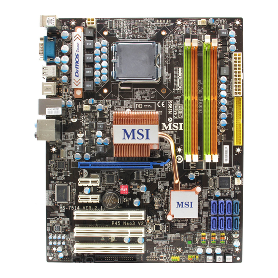
    Carte mère M S-7514 Guide rapide des composants SYSFAN2, Fr-16 PWR1, Fr-11 CPUFAN1, Fr-16 CPU, Fr-5 DDR2 DIMMs, Fr-9 JPWR1, Fr-11 Back Panel, Fr-12 IDE1, Fr-14 PCIE, SYSFAN1, Fr-24 Fr-16 JBAT1, Fr-21 1 2 3 OC_SW1, Fr-23 SATA, Fr-15 JTPM1, Fr-19 PCI, JUSB1~3,...
  • Page 84: Processeur : Cpu

    équipée d’un ventilateur de refroidissement attaché sur le dessus pour éviter la surchauffe. Si vous n’en avez pas, contactez votre revendeur pour en acheter et installez les avant d’allumer votre ordinateur. Pour plus d’informations sur le CPU, veuillez visiter http://global.msi.com.tw/index. php?func=cpuform Important Surchauffe La surchauffe endommage sérieusement l’unité...
  • Page 85: Installation Du Cpu Et Son Ventilateur

    Carte mère M S-7514 Installation du CPU et son ventilateur Quand vous installez le CPU, veuillez vous assurer que l’unité centrale soit équipée d’un ventilateur de refroidissement attaché sur le dessus pour éviter la surchauffe. Méanmoins, n’oubliez pas d’appliquer une couche d’enduit thermique sur le CPU avant d’installer le ventilateur pour une meilleure dissipation de chaleur.
  • Page 86 5. Levez le levier et ouvrir le plateau 6. Après avoir confirmé la direction de chargement. du CPU pour joindre correctement, déposez le CPU dans l’armature du logement de douille. Faites atten- tion au bord de sa base. Notez qu’on aligne les coins assortis. Clé...
  • Page 87 Carte mère M S-7514 9. Abaissez le levier sur le plateau de 10. Alignez les trous de la carte avec c h a r g e m e n t , p u i s s é c u r i s e r le dissipateur thermique.
  • Page 88: Mémoire

    Mémoire Ces slots de DIMM sont destinés à installer les modules de mémoire. Pour plus d’informations sur les composants compatibles, veuillez visiter http://global. msi.com.tw/index.php?func=testreport DDR2 240-pin, 1.8V 64x2=128 pin 56x2=112 pin Règles de population de la mémoire double-canaux : Au mode double-canaux, les modules de mémoire peuvent tranmettre et recevoir les données avec deux lignes bus de données sémultanément.
  • Page 89: Installation Des Modules De Mémoire

    Carte mère M S-7514 Installation des modules de mémoire 1. Le module de mémoire possède une seule encoche en son centre et ne s’adaptera que s’il est orienté de la manière convenable. 2. Insérez le module de mémoire à la verticale dans le slot du DIMM. Poussez-le ensuite jusqu’à...
  • Page 90: Connecteur D'alimentation

    Connecteur d’alimentation Connecteur d’alimentation ATX 24-Pin : JPWR1 pin 13 Ce connecteur vous permet de connecter l’alimentation ATX 24-pin. Pour cela, ass urez-vous que la prise d’alimentation est bien positionnée dans le bon sens et que les goupilles soient alignées. Enfoncez alors la prise dans le connecteur.
  • Page 91: Panneau Arrière

    Carte mère M S-7514 Panneau arrière Port 1394 (optionnel) Souris Line-In RS-Out Line-Out CS-Out Clavier SS-Out Port USB Port USB Port sérial Port USB Souris/Clavier ® Le standard connecteur de souris/clavier DIN de PS/2 est pour une souris ou un ®...
  • Page 92 Audio Ports Ces connecteurs audio servent pour les périphériques audio. Vous pouvez différencier la couleur des prises audio pour obtenir divers effets sonores. Ligne-In (Bleu) - Ligne In, est utilisée pour un appareil de CD externe, cassette ou d’autre périphériques. Ligne-Out (Vert) - Ligne Out, est destiné...
  • Page 93: Connecteurs

    Carte mère M S-7514 Connecteurs Connecteur Floppy Disk Drive : FDD1 Ce connecteur supporte le lecteur de disquette de 360KB, 720KB, 1.2MB, 1.44MB ou 2.88MB. Connecteur IDE : IDE1 Ce connecteur supporte les lecteurs de disque dur IDE, lecteurs optiques de disque et d’autre périphériques IDE.
  • Page 94: Connecteur Sérial Ata : Sata1

    Connecteur Sérial ATA : SATA1~8 Ce connecteur est un port d’interface de série ATA haut débit. Chaque connecteur peut être relié à un appareil de série ATA. SATA6 SATA4 SATA2 SATA8 SATA5 SATA3 SATA1 SATA7 Important 1. Veuillez ne pas plier le câble de série ATA à 90°. Autrement des pertes de données pourraient se produire pendant la transmission.
  • Page 95 Carte mère M S-7514 Connecteur d’alimentation du ventilateur : CPUFAN1, SYSFAN1~2 Les connecteurs de courant du ventilateur supportent le ventilateur de refroidissement du système avec +12V. Lors du branchement des fils aux connecteurs, faites toujours en sorte que le fil rouge soit le fil positif devant être relié au connecteur +12V;...
  • Page 96: Connecteur S/Pdif-Out : Jsp1

    Connecteur IEEE1394 : J1394_1 (optionnel) Ce connecteur vous permet de relier un appareil IEEE139 via un support optionnel IEEE1394. Définition de pins SIGNAL SIGNAL TPA+ TPA- Ground Ground J1394_1 TPB+ TPB- Cable power Cable power Key (no pin) Ground Support IEEE1394 (optionnel) Connecteur S/PDIF-Out : JSP1 Ce connecteur est utilisé...
  • Page 97: Connecteurs Du Panneau Avant : Jfp1, Jfp2

    Carte mère M S-7514 Connecteurs du panneau avant : JFP1, JFP2 Ces connecteurs sont fournis pour la connecxion électrique aux interrupteuts et LEDs du panneau avant. Le JFP1 est conforme au guide de conception de la connectivité Entrée/sortie du panneau avant Intel ® . Définition des pins pour JFP1 SIGNAL DESCRIPTION...
  • Page 98: Connecteur Audio Panneau Avant : Jaud1

    Connecteur audio panneau avant : JAUD1 Ce connecteur vous permet de connecter un audio sur le panneau avant. Il est conforme au guide de conception de la connectivité Entrée/sortie du panneau avant Intel ® . JAUD1 Définition de pins pourHD Audio SIGNAL DESCRIPTION MIC_L...
  • Page 99: Connecteur Usb Avant : Jusb1

    Carte mère M S-7514 Connecteur USB avant : JUSB1~3 Ce connecteur est conforme au guide de conception de la connectivité Entrée/sortie ® , il est idéal pour relier les périphériques d’interface USB à du panneau avant Intel haut débit tels les disques durs externes, les appareils photo numériques, les lecteurs M P3, les imprimantes, les modems et les appareils similaires.
  • Page 100: Cavalier

    Cavalier Cavalier d’effacement CMOS : JBAT1 Il y a un CMOS RAM intégré, qui possède un bloc d’alimentation alimenté par une batterie externe, destiné à conserver les données de configuration du système. Avec le CMOS RAM, le système peut lancer automatiquement le système d’exploitation chaque fois qu’il est allumé.
  • Page 101: Boutons

    Carte mère M S-7514 Boutons Cette carte mère vous fournit les boutons suivants (optinnel) pour régler les fonctions de l’ordinateur. Cette partie vous explique comment changer les fonctions de votre carte mère par ces boutons. Bouton d’alimentation : POWER1 (optionnel) Ce bouton d’alimentation sert à...
  • Page 102: Interrupteur

    Interrupteur Interrupteur du FSB d’overclocking du matériel : OC_SW1 Vous pouvez overclocker le FSB afin d’augmenter la fréquence du processeur en changeant l’interrupteur OC_SW 1. Suivez les instructions suivantes pour régler le FSB. 1 2 3 1 2 3 1 2 3 1 2 3 1 2 3 Défaut...
  • Page 103: Slots

    Carte mère M S-7514 Slots Slot PCI (Peripheral Component Interconnect) Express Le slot PCI Express supporte la carte d’expension de l’interface du PCI Express. Le slot PCI Express 2.0x 16 supporte un taux de transfert jusqu’à 8.0 GB/s. Le slot PCI Express x 1 supporte un taux de transfert jusqu’à 250 MB/s. Slot PCI Express x16 Slot PCI Express x 1 Slot PCI (Peripheral Component Interconnect)
  • Page 104: Indicateurs De Statuts De Led

    Indicateurs de statuts de LED LED3 LED1 LED2 LED4 1 2 3 Lumière bleue Eteint LED4 LED3 LED2 LED1 M o de CPU est dans le mode d’alimentation phase 1. CPU est dans le mode d’alimentation phase 2. CPU est dans le mode d’alimentation phase 3. CPU est dans le mode d’alimentation phase 4.
  • Page 105: Réglages Bios

    Carte mère M S-7514 Réglages BIOS Ce chapitre donne des informations concernant le programme de réglage de BIOS et vous permet de configurer le système pour obtenir des performances d’utilisation optimum. Vous aurez peut-être besoin de lancer le programme de réglage quand : * Un message d’erreur apparaît sur l’écran pendant le démarrage du système, qui vous demande de lancer SETUP (Réglage).
  • Page 106 Réglages d’Entrée Allumez l'ordinateur et le système lancera le processus POST (Test automatique d'allumage). Lorsque le message ci-dessous apparaît à l'écran, appuyez sur la tou- che <DEL> pour entrer dans les réglages. Appuyez sur DEL pour entrer dans SETUP Si le message disparaît avant que vous ne répondiez et que vous souhaitez encore entrer dans Setup (Réglages), redémarrez le système en OFF (éteignant) puis en On (rallumant) en appuyant sur le bouton RESET (Réinitialiser).
  • Page 107 Carte mère M S-7514 M enu principal ® ® Une fois entré dans l’unité de réglages AMI ou AWARD BIOS CMOS, le Menu princi- pal appaît sur l’écran. Le Menu Principal vous permet de sélectionner de dix foncions de réglage et deux choix de sortie. Utilisez les touches de flèche pour sélectionner parmi les objets et appuyez sur <Enter>...
  • Page 108 Choisir [Ok] et appuyer sur Enter afin de sauvegarder les configurations et l’unité de réglages de quitter BIOS. Important Les configurations précédantes ne sont que pour l’utilisation générale. Si vous avez besoin de réglages détaillés du BIOS, veuillez vous référer au manuel de l’édition anglaise sur la page d’internet de MSI. Fr-29...
  • Page 109 Carte mère M S-7514 4. Cell M enu Introduction (Introduction du Menu cell) : Ce menu est pour des utilisations avancée destinée à overclocker la carte mère. Important Ne changez pas ces réglages sauf que vous connaissiez bien ces chipsets. Current CPU/ DRAM Frequency (Fréquence actuelle du CPU/ DRAM) Ces articles montrent les horloges actuelles de la vitesse du CPU et de la mémoire.
  • Page 110 D.O.T. Control D.O .T. (Dynamic Overc loc king Technology) es t une fonc tion d’overclocking automatique, compris dans la Technologie Dual CoreCell , récemment dévelopée par ’. Elle est destinée à détecter l’équilibre de charge du CPU pendant la procédure des programme, et à...
  • Page 111 Carte mère M S-7514 Advance DRAM Configuration Appuyez sur <Enter> pour entrer dans le sous-menu et il apparaîtra l’écran suivant. MEMORY-Z Appuyez sur <Enter> pour entrer dans le sous-menu et il apparaîtra l’écran suivant. DIM M1~4 Memory SPD Infromation Appuyez sur <Enter> pour entrer dans le sous-menu et il apparaîtra l’écran suivant.
  • Page 112 Advance Memory Setting La mise en [Auto] rend le timing de mémoire avancée automatiquement déterminé par BIOS. La mise en[Manual] vous permet de régler les timings de mémoire avancée. TRFC Quand cet Advance M emory Setting est mis en [Manual], ce domaine est ajustable.
  • Page 113 Carte mère M S-7514 CPU Clock Drive/ PCI Express Clock Drive Ces articles servent à sélectionner l’amplitude d’horloge du CPU/ PCI Express. CPU CLK Skew/ M CH CLK Skew Ces articles servent à sélectionner l’obliquité d’horloge du chipset du CPU/ North Bridge.
  • Page 114: Information De Logiciel

    Menu de services – Il montre les applications logicielles supportées par la carte mère. Menu du site Web – Il vous indique les sites webs utiles. Important Veuillez consulter le site Web de MSI pour obtenir les derniers pilotes et BIOS pour améliorer l’exécution du système de votre ordinateur. Fr-35...
  • Page 115: Руководство Пользователя

    Серия P45 Neo3 V2 / P43 Neo3 V2 Руководство пользователя Русский Ru-1...
  • Page 116: Характеристики

    Pentium Dual-Core и Celeron Dual-Core в конструктиве LGA775 - Многоядерные процессоры Intel 45 nm последнего поколения ® *(Для получения самой новой информации о CPU, посетите сайт http://global.msi.com.tw/index.php?func=cpuform) - 1600*(OC)/ 1333/ 1066/ 800 МГц Чипсет - Северный мост: Intel ® P45/ P43 - Южный...
  • Page 117 1394 (опционально) - Поддержка 1394 на чипсете JMicron JMB381 - 1 флоппи порт - Поддержка 1 FDD с 360KB, 720KB, 1.2MB, 1.44MB и 2.88MB Коннекторы Задней панели - 1 PS/2 порт мыши - 1 PS/2 порт клавиатуры - 1 последовательный порт - 6 портов...
  • Page 118: Руководство По Размещению Компонентов

    MS-7514 Системная плата Руководство по размещению компонентов SYSFAN2, Ru-16 PWR1, Ru-11 CPUFAN1, Ru-16 CPU, Ru-5 DDR2 DIMMs, Ru-9 JPWR1, Ru-11 Back Panel, Ru-12 IDE1, Ru-14 PCIE, SYSFAN1, Ru-24 Ru-16 JBAT1, Ru-21 1 2 3 OC_SW1, Ru-23 SATA, Ru-15 JTPM1, Ru-19 PCI, JUSB1~3, Ru-24...
  • Page 119: Cpu (Центральный Процессор)

    кулера, пожалуйс та, свяжитес ь с дилером с цель ю приобретения и его установки до того, как включите компьютер. Самую последнюю информацию о CPU можно получить на сайте http://global. msi.com.tw/index.php?func=cpuform Внимание Перегрев Перегрев может серьезно повредить центральный процессор и систему.
  • Page 120 MS-7514 Системная плата Установка процессора и вентилятора Во избежание перегрева при работе обязательно установите вентилятор процессора. Одновременно, чтобы увеличить теплорассеивание, убедитесь в том, что нанесен слой теплопроводящей пасты на процессоре при установке вентилятора. Следуйте данным указаниям для правиль ной ус тановки. Неправильная...
  • Page 121 5. Поднимите рычаг и откройте 6. У б ед и в ш и с ь в п р ав и л ь н ой метал лич ес к ую кр ышк у д ля о р и е н т а ц и и п р о ц е с с о р а , установки...
  • Page 122 MS-7514 Системная плата 9. Аккуратно опус тите рычаг на 10. Совместите отверстия системной крышку механизма крепления и платы с защелками крепления зафиксируйте его. Для фиксации вентилятора. Прижмите радиатор рычага в механизме крепления с вентилятором к процессору и п р ед ус м от р ен с п ец и ал ь н ы й проследите, чтобы...
  • Page 123: Память

    Память Слоты DIMM используются для установки модулей памяти. За дополнительной информацией о совместимых компонентах по сетите сайт http://global.msi.com.tw/index.php?func=testreport DDR2 240-pin, 1.8V 64x2=128 pin 56x2=112 pin Правила установки модулей памяти для работы в двухканальном режиме В двухканальном режиме модули памяти могут передавать и принимать...
  • Page 124 MS-7514 Системная плата Установка модулей памяти 1. Модули памяти имеют только одну прорезь в середине. Модуль войдет в разьем только при правильной ориентации. 2. Вставьте модуль в DIMM слот в вертикальном направлении. Затем нажмите на него, чтобы золоченые контакты глубоко погрузились в DIMM слот. Если модуль...
  • Page 125: Разъем Питания

    Разъем питания 24-контактный разъем питания ATX: JPWR1 pin 13 Этот разъем позволяет подключить 24-контактный питания ATX. Для подключения источника убедитесь, что его разъем и контакты правильно сориентированы. Затем плотно вставьте его в разъем на системной плате. Вы также можете ис поль зовать 20-контактный AT X блок п...
  • Page 126: Задняя Панель

    MS-7514 Системная плата Задняя панель (опционально) 1394 Port Mouse Line-In RS-Out Line-Out CS-Out Keyboard SS-Out USB Port USB Port Serial Port USB Port Разъемы мыши/клавиатуры Стандартные разъемы DIN PS/2 для подключения мыши/клавиатуры с ® интерфейсом PS/2 ® Разъем последовательного порта Это...
  • Page 127 Аудио разъемы Эти разъемы используются для подключения звуковых устройств. Разъемы, выполняющие разные функции, имеют различные цвета. Вход аудио (Голу бой) - Л инейный вход, ис поль зуетс я для п о д к л ю ч е н и я в н е ш е г о C D п р о и г р ы в а т е л я , магнитофоноа...
  • Page 128: Разъемы

    MS-7514 Системная плата Разъемы Разъем FDD: FDD1 Разъем поддерживает FDD ёмкостью 360KB, 720KB, 1.2MB, 1.44MB или 2.88MB. Разъем IDE: IDE1 Разъем поддерживает жёсткий диск IDE, дополнительное дисковое устройство и другие устройства с интерфейсом IDE. Внимание При подключении двух устройств на одном кабеле, следует установить устройства...
  • Page 129 Разъем Serial ATA: SATA1~8 Данный разъем является высокоскоростным портом интерфейса Serial ATA. Любой разъем Serial ATA может соединяться с одним устройством Serial ATA. SATA6 SATA4 SATA2 SATA8 SATA5 SATA3 SATA1 SATA7 Внимание 1. Избегайте, пожал уйста, резких изгибов к абеля Serial ATA. В противном...
  • Page 130 MS-7514 Системная плата Разъемы питания вентиляторов: CPUFAN1, SYSFAN1~2 Разъемы питания вентиляторов поддерживают вентиляторы с питанием +12В. При подключении необходимо помнить, что красный провод подключается к шине +12В, черный - к земле GND. Если на системной плате установлена микросхема аппаратного мониторинга, необходимо использовать...
  • Page 131 Разъем IEEE1394: J1394_1 (опционально) Этот коннектор позволяет подключить порты IEEE1394 на выносной планке IEEE1394. Pin Definition SIGNAL SIGNAL TPA+ TPA- Ground Ground J1394_1 TPB+ TPB- Cable power Cable power Key (no pin) Ground IEEE1394 Bracket (опционально) Разъем S/PDIF-Out: JSP1 Этот разъем используется для подключения интерфейса S/PDIF (Sony & Philips Digital Interconnect Format) для...
  • Page 132 MS-7514 Системная плата Коннекторы передней панели: JFP1, JFP2 Эти коннекторы ис поль зуются для подключения кнопок и индикаторов, расположенных на передней панели корпуса. Коннектор JFP1 соответствует руководству Intel ® Front Panel I/O Connectivity Design. JFP1 Pin Definition SIGNAL DESCRIPTION Power Power Switch HD_LED +...
  • Page 133 Выносной разъем аудио: JAUD1 Этот коннектор позволяет подключить выносной разъем аудио на передней панели и соответствует руководству Intel ® Front Panel I/O Connectivity Design. JAUD1 HD Audio Pin Definition SIGNAL DESCRIPTION MIC_L Microphone - Left channel Ground MIC_R Microphone - Right channel LINE out_R Analog Port - Right channel MIC_JD...
  • Page 134 MS-7514 Системная плата Разъем USB передней панели: JUSB1~3 Разъем, соответствует спецификации Intel ® I/O Connectivity Design, идеально подходит для подключения таких высокоскоростных периферийных устройств, как USB HDD, цифровые камеры, MP3 плееры, принтеры, модемы и им подобные. Pin Definition SIGNAL SIGNAL USB0- USB1- USB0+...
  • Page 135: Перемычки

    Перемычки Перемычка очистки CMOS: JBAT1 На плате установлена CMOS память с питанием от батарейки, хранящая данные о конфигурации системы. С помощью памяти CMOS, система автоматически загрузится каждый раз при включении. Если у вас возникает необходимость сбросить конфигурацию системы (очистить CMOS), вос пользуйтесь этой перемычкой.
  • Page 136: Кнопки

    MS-7514 Системная плата Кнопки На этой системной плате имеются дополнительные кнопки (опционально) для ус т ан ов к и фун к ц и й к ом п ь ю т ер а. Э т а г л ав а п оя с н я е т в оз м ож н ос т и использования...
  • Page 137: Переключатели

    Переключатели Переключатели аппаратного разгона FSB: OC_SW1 Перестановка переключателей O C_SW 1 позволяет разогнать FSB для увеличения частоты процессора. Следуйте данным указаниям для установки FSB. 1 2 3 1 2 3 1 2 3 1 2 3 1 2 3 Default 200->266 MHz 200->333 MHz 266->333 MHz...
  • Page 138: Слоты

    MS-7514 Системная плата Слоты Слот PCI (Peripheral Component Interconnect) Express Слот PCI Express поддерживает карты расширения интерфейса PCI Express. PCI Express 2.0x 16 поддерживает скорость передачи данных до 8.0 ГБ/с. PCI Express x 1 поддерживает скорость передачи данных до 250 МБ/с. Слот...
  • Page 139: Световые Индикаторы

    Световые индикаторы LED3 LED1 LED2 LED4 1 2 3 Blue Light LED4 LED3 LED2 LED1 M o de CPU использует 1 фазу питания. CPU использует 2 фазы питания. CPU использует 3 фазы питания. CPU использует 4 фазы питания. Ru-25...
  • Page 140: Настройка Bios

    MS-7514 Системная плата Настройка BIOS В этой главе приводятся основные сведения о режиме настройки BIOS (BIOS SETUP), который позволяет установить оптимальную конфигурацию системы. Этот режим может потребоваться в следующих случаях: * Во время загрузки системы появляется сообщение об ошибке с требованием запустить...
  • Page 141: Режим Настройки

    Вход в режим настройки Включите питание компьютера. При этом запустится процедура POST (Тест включения питания). Когда на экране появится приведенное ниже сообщение, нажмите клавишу <DEL> для входа в режим настройки. Press DEL to enter SETUP Если сообщение исчезло, а вы не ус пели нажать клавишу, перезапустите систему, выключив...
  • Page 142 MS-7514 Системная плата The M ain Menu При входе в режим настройки BIOS CMOS от AMI ® или AWARD ® на экране отображается Главное меню. Главное меню позволяет выбрать десять функций настройки и имеет два варианта выхода. Для перемещения по пунктам используются клавиши со стрелками...
  • Page 143 следующее сообщение: Выберите [Ok] и нажмите Enter, чтобы сохранить конфигурацию и выйти из BIOS Setup. Внимание Приведенная выше конфигурация подходит для общего применения. Если же вам требуются более тонкие настройки BIOS, обратитесь к английской версии руководства на веб-сайте MSI. Ru-29...
  • Page 144 MS-7514 Системная плата 4. Cell M enu Introduction: Это меню позволяет управлять тактовыми частотами при разгоне. Внимание Вы можете изменять эти настройки, только если хорошо знакомы с чипсетом. Current CPU / DRAM Frequency Эти пункты показывают текущие частоту CPU и памяти. Только для чтения. Multi-step OC Booster Этот...
  • Page 145 D.O.T. Control D.O.T. (Dynamic Overclocking Technology) - это функция автоматического разгона, реализованная благодаря новой технологии CoreCell ’. Она способна определять уровень загрузки процессора при работе различных программ, и автоматически регулировать частоту CPU. Автоматически ускоряя скорость процессора, данная технология позволяет программам работать ровнее и быстрее.
  • Page 146 MS-7514 Системная плата Advance DRAM Configuration Нажмите <Enter> для входа в подменю и появляется нижеследующий экран. MEMORY-Z Нажмите <Enter> для входа в подменю и появляется нижеследующий экран. DIM M1~4 Memory SPD Infromation Нажмите <Enter> для входа в подменю и появляется нижеследующий экран. DIM M1~4 Memory SPD Infromation Этот...
  • Page 147 TRFC При установке значения Advance Memory Setting в [Manual], этот пункт становится доступным. Эта установка определяет временную задержку между последовательными командами чтения или записи в ячейку памяти. При установке значения Advance Memory Setting в [Manual], этот пункт становится доступным. Минимальная временная задержка для выполнения операции...
  • Page 148 MS-7514 Системная плата CPU CLK Skew/ M CH CLK Skew Эти пункты используются для выбора задержек тактового сигнала для северного моста/ процессора, благодаря которым CPU может достигнуть более высокой частоты разгона. Adjust PCI Frequency (М Гц) Этот пункт позволяет выбрать тактовую частоту PCI (в МГц). Auto Disable DRAM /PCI Frequency При...
  • Page 149: Сведения О Программном Обеспечении

    для активации устройства. Utility menu (Меню утилит) - Содержит прикладные программы для поддержки системной платы. W ebSite menu (Меню вебсайтов) - Содержит список необходимых вебсайтов. Внимание Если же вам требуются более тонкие настройки BIOS, обратитесь к руководству на веб-сайте MSI. Ru-35...

Ce manuel est également adapté pour:

P43 neo3 v2 serieMs-7514G52-75141xb

Table des Matières