Table des Matières

Publicité

Les langues disponibles
  • FR

Les langues disponibles

Liens rapides

MINDY
I
A6-A6F
A700F
Centrale
Electronic
elettronica di
control unit for
controllo per
2-winged
cancelli a due
gates
ante
QUESTO LIBRETTO È DESTINATO SOLO ALL'INSTALLATORE.
L'installazione dovrà essere effettuata solamente da personale professionalmente qualificato in conformità a quanto previsto dalla
legge n° 46 del 5 marzo 1990 e successive modifiche ed integrazioni e nel pieno rispetto delle norme UNI 8612.
GB
A6-A6F
A700F
Centrale
électronique
de contrôle
pour portails à
deux battants
F
D
A6-A6F
A700F
Elektronische
Steuerzentrale
für
Zweiflügeltore
E
A6-A6F
A6-A6F
A700F
Central
electrónica de
control para
verjas de dos
hojas
V. 006
A700F

Publicité

Table des Matières
loading

Sommaire des Matières pour Nice MINDY A6-A6F

  • Page 1 V. 006 MINDY A6-A6F A6-A6F A6-A6F A6-A6F A6-A6F A700F A700F A700F A700F A700F Centrale Electronic Centrale Elektronische Central elettronica di control unit for électronique Steuerzentrale electrónica de controllo per 2-winged de contrôle für control para cancelli a due gates pour portails à Zweiflügeltore verjas de dos ante...
  • Page 3: Table Des Matières

    (Recepimento direttiva 93/68 CEE, Direttiva Bassa Tensione) Nella progettazione e realizzazione dei propri prodotti, Nice, rispetta (per quanto compete alle apparecchiature) tutte queste normative, è fondamentale però che anche l’installatore (per quanto compete agli impianti) prosegua nel rispetto scrupoloso delle medesime norme.
  • Page 4: Guida Rapida

    Italiano GUIDA RAPIDA: Non installare la centrale senza aver letto tutte le istruzioni! Prima di iniziare l’installazione verificare la robustezza e la consistenza meccanica dell’anta, il rispetto dei franchi di sicurezza e delle distanze minime. Valutare con particolare attenzione i dispositivi di sicurezza da applicare ed installare sempre un dispositivo di arresto d’emergenza vale a dire arresto di categoria 0.
  • Page 5 Italiano • Alimentare la centrale, verificare che tra morsetti 1-2 e 1-3 vi siano 230 Vca e che sui morsetti 21-22 vi siano 24 Vca; i LED posti sugli ingressi di contatti NC devono accendersi ed il led OK dovrà lampeggiare alla frequenza di 1 al secondo. •...
  • Page 6: Introduzione

    Tutte le centrali sono predisposte per l’inserimento della vasta gamma di ricevitori radio prodotti da Nice, Nel progetto sono state adottate le piú avanzate tecniche per garantire la massima immunità nei confronti dei disturbi, la maggiore flessibilità...
  • Page 7: Istruzioni Per L'installazione

    Italiano 2) ISTRUZIONI PER L’INSTALLAZIONE: Non installare la centrale senza aver letto tutte le istruzioni della centrale e degli attuatori! Prima di iniziare l’installazione verificare la robustezza e la consistenza meccanica del cancello, il rispetto dei franchi di sicurezza e delle distanze minime. Seguire scrupolosamente tutte le indicazioni riportate nei manuali di istruzioni dei motoriduttori. Eseguire una attenta e scrupolosa analisi dei rischi connessa all’automazione, valutare con particolare attenzione i dispositivi di sicurezza da applicare ed installare sempre un dispositivo di arresto di emergenza cioè...
  • Page 8: Schema Dei Collegamenti

    Italiano Una volta terminata l’installazione delle varie parti il quadro dell’insieme dovrebbe risultare simile al seguente disegno: Fig 3 1: Linea di alimentazione 230 V 2: Centrale A6, A6F o A700F 3: Lampeggiante LUCY 4: Coppia fotocellule (FOTO) 5: Attuatori elettromeccanici 6: Coppia fotocellule (FOTO 1) LINE 230 vac NOTA: Questo schema rappresenta solo una possibile applicazione della centrale e va considerata solo come...
  • Page 9: Descrizione Dei Collegamenti

    Italiano Fig. 4 RADIO FUSE 500mA ANT. 2° Ch RADIO FUNZIONI 1-10 FUNZIONI 11-20 FUSE PIU' 10 11 12 13 14 15 16 17 18 19 20 21 22 23 24 25 26 27 28 29 La parte evidenziata è presente solo sulla versione A700F La parte evidenziata è...
  • Page 10: Note Sui Collegamenti

    PLUTO PL 4000 prodotto da Nice hanno già questo condensatore collegato internamente, altri invece richiedono il collegamento del condensatore esternamente, ad esempio il modello METRO ME 3000 sempre prodotto da Nice. In questo caso il condensatore va collegato fra le fasi APRE e CHIUDE del motore. Per praticità è opportuno inserire il condensatore...
  • Page 11: Collaudo

    Italiano La seguente parte è relativa solo alla versione A700F Fig. 5 21 22 23 26 27 Una particolare descrizione merita venga rivolta all’uscita “Fototest”, questa non è altro che la massima soluzione possibile in termini di affidabilità nei confronti dei dispositivi di sicurezza. Ogni volta che FOTO viene avviata una manovra vengono controllati i dispositivi di sicurezza coinvolti e solo se tutto è...
  • Page 12 Italiano La seguente parte è relativa solo alla versione A700F C) Verificare che sui morsetti 14-15 sia presente una tensione di 24 Vac per alimentazione trasmettitori delle fotocellule. Non appena la centrale è alimentata le spie luminose (LED) che sono poste sugli ingressi attivi devono illuminarsi, inoltre dopo pochi istanti il led “OK”...
  • Page 13: Regolazioni

    Italiano 3.1) REGOLAZIONI : Se il cancello è composto da 2 ante che si = Tempo Lavoro Maggiorato possono incagliare se in apertura partono contemporaneamente o se in chiusura una si = Tempo Lavoro sovrappone all’altra, allora è necessario = Tempo Pausa intervenire sulle regolazioni dei trimmer Tempo = Tempo Ritardo Apertura Ritardo Apertura “TRA”...
  • Page 14: Modi Di Funzionamento

    Italiano 3.2) MODI DI FUNZIONAMENTO: Nota: alcune delle parti descritte a seguito sono relative solo alla versione A700F Nel funzionamento in modo manuale, l’ingresso APRE consente il movimento in apertura, l’ingresso CHIUDE consente il movimento in chiusura. il PASSO P. consente il movimento alternativamente in apertura e in chiusura; non appena cessa il comando in ingresso il movimento si arresta.
  • Page 15: Descrizione Delle Funzioni

    Italiano Nella versione A700F è presente un secondo gruppo di dip-switch con altre funzioni: Switch 11 = Funzione posizionamento < > solo con l’utilizzo dei finecorsa Switch 12 = Lampeggiante anche in Pausa < > solo in modo Automatico Switch 13 = Mantenimento pressione Switch 14 = Spia C.A.
  • Page 16 Italiano Switch 8: On = Fermata graduale Quando il movimento termina viene eseguita una fermata in modo graduale inviando una forza sempre minore al motore con un decremento che dura circa 1 Sec, questo garantisce che la fermata avvenga senza scossoni. Per ovvi motivi di sicurezza la fermata graduale non avviene, e viene sostituita da una fermata normale, quando interviene ALT, FOTO e FOTO1o FOTO2 (su scheda PIU’) oppure uno dei finecorsa.
  • Page 17: Accessorio : Scheda Espansioni Piu

    Italiano di malfunzionamento si aumenta la sicurezza dell’impianto. Per sfruttare la funzione Fototest è necessario che i trasmettitori delle fotocellule siano collegati all’apposita uscita (vedere: Note dei collegamenti). Switch 16 = Foto e Foto1 anche in apertura Normalmente le sicurezze FOTO e FOTO1 intervengono solo nella manovra di chiusura, se il dip-switch N° 16 viene attivato l’intervento dei dispositivi di sicurezza provocano una interruzione del movimento anche in apertura, se in Semiautomatico od Automatico si avrà...
  • Page 18: Caratteristiche Tecniche Della Centrale

    : 2,7 Kg circa Grado di protezione : IP 55 Nice s.r.l. si riserva il diritto di apportare modifiche ai prodotti in qualsiasi momento senza preavviso. NOTE FINALI : Il presente manuale è destinato solamente al personale tecnico qualificato per l’installazione.
  • Page 19 (EEC directive 93/68, Low Voltage Directive) When designing and producing its products, Nice observes (as regards the equipment) all the above standards but it is of paramount importance that the installer too (as regards the systems) continues the strict observance of the same standards.
  • Page 20: Quick Guide

    English QUICK GUIDE: Do not install the unit before you have read all the instructions! Before you actually start installing the unit check the sturdiness and mechanical consistency of the wing and the observance of safety margins and minimum distances. Evaluate with particular care the safety devices to be installed and always install an emergency stop device, in other words, a category 0 stop device.
  • Page 21 English • If the limits switches are installed on the A700F version, check correspondence of the four LEDs: FCA1, FCA2 FCC1 and FCC2; when the gates are closed only the two FCC LEDs should turn off and when they are open only the two FCA LEDs should turn off. •...
  • Page 22: Introduction

    In the A700F version, by plugging in the “PIU” model expansions cards, you can expand the functions even more by means of other inputs and outputs. All the units are designed for connecting a wide range of Nice made radio receivers. The most advanced techniques have been adopted in the project to guarantee maximum immunity to interference, greater flexibility of use and the widest choice of programmable functions.
  • Page 23: Installation Instructions

    English 2) INSTALLATION INSTRUCTIONS: Do not install the unit without first having read the instructions for the unit and actuators! Before you actually start installation, check the sturdiness and mechanical consistency of the gate and the observance of safety margins and minimum distances. Follow exactly all the indications given in the gearmotor instruction manuals. Once you have carefully analysed the risks involved with the automation, evaluate with particular care, the safety devices to be installed and always install an emergency stop device, in other words, a category 0 stop device.
  • Page 24: Diagram Of Connections

    English Once everything has been installed it ought to look something like this drawing: Fig. 3 1: 230 V power line 2: A6, A6F or A700F unit 3: LUCY flashing lamp 4: Couple of photoelectric cells (PHOTOCELL) 5: Electromechanical actuators 6: Couple of photoelectric cells (PHOTOCELL 1) LINE 230 vac...
  • Page 25: Description Of Connections

    English Fig. 4 RADIO FUSE 500mA ANT. 2° Ch RADIO FUNCTIONS 1-10 FUNCTIONS 11-20 FUSE PIU' 10 11 12 13 14 15 16 17 18 19 20 21 22 23 24 25 26 27 28 29 The highlighted part is only found on the A700F version. The highlighted part is found on the A6F and A700F versions.
  • Page 26: Notes About Connections

    PLUTO PL 4000 model made by Nice have this capacitor already connected inside while others have to have the capacitor connected externally like, for instance, the METRO ME 3000 model, also made by Nice. In this case, the capacitor must be connected between the motor’s OPEN and CLOSE phases.
  • Page 27: Test

    English The following is applicable only to the A700F version Fig. 5 A particular description is given about the “Phototest” output which is nothing else but the best possible solution in terms of reliability as 23 26 27 regards safety devices. Each time a manoeuvre is activated the relevant safety devices are checked and only if everything is in order PHOTOCELL will the manoeuvre start...
  • Page 28 English The following refers only to the A700F version C) Check that voltage on terminals 14-15 is 24 V a.c. for powering the photoelectric cell transmitters. As soon as the unit is powered the indicator lights (LEDs) on the active inputs should light up; in addition, the “OK” LED should start flashing almost immediately afterwards at regular intervals.
  • Page 29: Adjustments

    English 3.1) ADJUSTMENTS: If the gate has 2 wings that could get bump = Increased Working Time into each other if, when opening, they start simultaneously or, when closing, one moves = Working Time on top of the other, you will have to readjust = Pause Time the Opening Delay Time trimmer “TRA”...
  • Page 30: Functioning Modes

    English 3.2) FUNCTIONING MODES: Note: some of the parts described below refer only to the A700F version In the manual functioning mode the OPEN input consents to the opening manoeuvre, the CLOSE input consents to the closing manoeuvre, the STEP-BY-STEP consents to an alternating closing and opening manoeuvre; as soon as the command in input stops, movement stops.
  • Page 31: Description Of The Functions

    English There is a second set of dip-switches with other functions in the A700F version: Switch 11 = Positioning function < > only with the aid of the limit switch Switch 12 = Flashing also in Pause < > Only in the Automatic mode Switch 13 = Pressure holding Switch 14...
  • Page 32 English Switch 8: = Gradual stop When movement finishes, a gradual stop is carried out, sending a diminishing force to the motor with a decrement that lasts about 1 second; this guarantees a jolt-free stop. For obvious safety reasons, when STOP, PHOTOCELL and PHOTOCELL 1 or PHOTOCELL 2 (on the PIU’ card) or one of the limit switches trigger, there is no gradual stop, being replaced by an ordinary stop.
  • Page 33 English Switch 16 = Photocell and Photocell 1 also in opening The safety devices PHOTOCELL and PHOTOCELL 1 normally trigger only in the closing manoeuvre; if dip-switch no. 16 is activated, triggering of the safety devices will cause movement to be interrupted even in the opening phase; if it is set on Semiautomatic or Automatic, movement in the opening direction will start again as soon as the last object has passed by the photoelectric cell.
  • Page 34: Technical Features Of The Unit

    : approx. 2.7 Kg Protection level : IP 55 Nice s.r.l. reserves the right to modify its products at any time without prior notice. FINAL NOTES: This manual is for use only by technical personnel qualified to carry out the installation.
  • Page 35 (Adoption directive 93/68 CEE, Directive Basse Tension) Dans le projet et dans la fabrication de ses produits, Nice respecte toutes ces normes (en ce qui concerne ses appareils); il est indispensable toutefois que l’installateur lui aussi continue à respecter scrupuleusement ces mêmes normes (en ce qui concerne les installations).
  • Page 36: Guide Rapide

    Français GUIDE RAPIDE: Ne pas installer la centrale sans avoir lu toutes les instructions! Avant de commencer l’installation, vérifier la robustesse et la consistance mécanique du battant, le respect des dégagements de sécurité et des distances minimum. Examiner avec une attention particulière les dispositifs de sécurité à appliquer et installer toujours un dispositif d’arrêt d’urgence à...
  • Page 37 Français Vca; les DEL situées sur les entrées de contact NF doivent s’allumer et la DEL OK doit clignoter à la fréquence d’1 clignotement à la seconde. • Si des microinterrupteurs de fin de course sont installés, dans la version A700F contrôler la correspondance des quatre DEL FCA1, FCA2 FCC1 et FCC2, quand les battants sont fermés, seules les deux DEL FCC doivent s’éteindre, quand ils sont ouverts, seules les deux FCA doivent s’éteindre.
  • Page 38: Introduction

    Toutes les centrales sont prévues pour le branchement de la vaste gamme de récepteurs produits par Nice. On a adopté pour le projet les techniques les plus avancées pour garantir le maximum de protection contre les parasites, une grande flexibilité...
  • Page 39: Instructions Pour L'installation

    Français 2) INSTRUCTIONS POUR L’INSTALLATION: Ne pas installer la centrale sans avoir lu toutes les instructions inhérentes à la centrale et aux actionneurs! Avant de commencer l’installation, vérifier la robustesse et la consistance mécanique du portail, le respect des dégagements de sécurité...
  • Page 40: Schéma Des Connexions

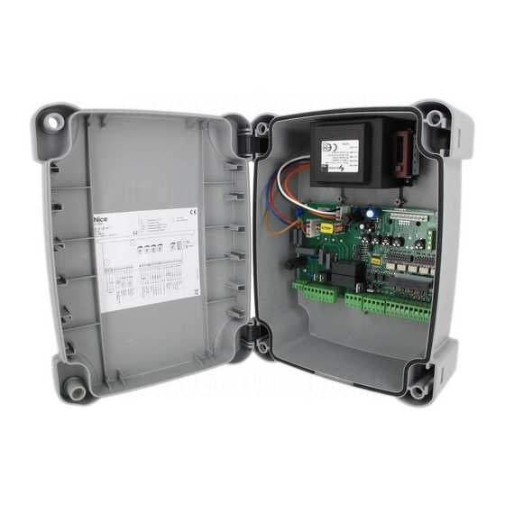
    Français Une fois que l’installation des différentes parties est terminée, le tableau de l’ensemble doit résulter semblable au dessin suivant: Fig 3 1: Ligne d’alimentation 230 V 2: Centrale A6, A6F ou A700F 3: Clignotant LUCY 4: Paire de photocellules (PHOTO) 5: Actionneurs électromécaniques 6: Paire de photocellules (PHOTO 1) LINE 230 vac...
  • Page 41: Description Des Connexions

    Français Fig. 4 RADIO FUSIBLE 500mA ANTENNE 2e CANAL RADIO FONCTIONS 1-10 FONCTIONS 11-20 FUSIBLE PIU' 10 11 12 13 14 15 16 17 18 19 20 21 22 23 24 25 26 27 28 29 La partie avec fond tramé est présente seulement sur la version A700F La partie avec fond tramé...
  • Page 42: Notes Sur Les Connexions

    à l’extérieur, par exemple le modèle METRO ME 3000 toujours produit par Nice. Dans ce cas, le condensateur doit être connecté entre les phases OUVRE et FERME du moteur. Par commodité il est bon...
  • Page 43: Essai De Fonctionnement

    Français La partie qui suit se réfère uniquement à la version A700F Fig. 5 La sortie “Test photocellule” mérite une description particulière: il s’agit en effet de la solution la plus fiable possible en termes de fiabilité en 23 26 27 ce qui concerne les dispositifs de sécurité.
  • Page 44 Français La partie qui suit concerne uniquement la version A700F C) Vérifier que sur les bornes 14-15 il y a bien une tension de 24 Vac pour l’alimentation des émetteurs des photocellules. Dès que la centrale est alimentée, les voyants (DEL) situés sur les entrées actives doivent s’allumer, en outre, quelques instants plus tard, la DEL “OK”...
  • Page 45: Réglages

    Français 3.1) REGLAGES: Si le portail est composé de 2 battants qui = Temps Travail Majoré peuvent se coincer s’ils partent en même temps en ouverture ou si l’un des deux = Temps Travail battants se superpose à l’autre en fermeture, = Temps Pause il faut intervenir sur les réglages des trimmers = Temps Retard Ouverture...
  • Page 46: Modes De Fonctionnement

    Français 3.2) MODES DE FONCTIONNEMENT: Note : quelques unes des parties décrites ci-après se réfèrent uniquement à la version A700F Dans le fonctionnement en mode manuel, l’entrée OUVRE permet le mouvement en ouverture, l’entrée FERME permet le mouvement en fermeture. L’entrée PAS-A-PAS permet le mouvement alternativement en ouverture et en fermeture; dès que la commande cesse en entrée le mouvement s’arrête.
  • Page 47: Description Des Fonctions

    Français Dans la version A 700F se trouve un groupe de dip-switchs avec d’autres fonctions: Dip-switch 11 : = Fonction positionnement < > Seulement avec utilisation microint. de fin de course Dip-switch 12 : = Clignotement également en Pause < >...
  • Page 48 Français Dip-switch 8: On = Arrêt progressif Quand le mouvement s’achève, on a un arrêt progressif effectué en envoyant une force de plus en plus faible au moteur avec un décrément qui dure environ 1 s, ce qui garantit un arrêt sans secousses. Pour des raisons évidentes de sécurité, l’arrêt progressif ne se produit pas et est remplacé...
  • Page 49: Accessoire : Carte Expansions Piu

    Français Dip-switch 16: = PHOTO et PHOTO1 également en ouverture Normalement les sécurités PHOTO et PHOTO1 interviennent seulement dans la manoeuvre de fermeture, si le dip-switch N° 16 est activé, l’intervention des dispositifs de sécurité provoque une interruption du mouvement également en ouverture. Si on est en mode semi-automatique ou Automatique, on aura la reprise de nouveau du mouvement en ouverture juste après le dégagement de la photocellule.
  • Page 50: Caractéristiques Techniques De La Centrale

    : 2,7 Kg environ Indice de protection : IP 55 Nice s.r.l. se réserve le droit d’apporter des modifications aux produits à tout moment sans préavis. NOTES FINALES: Le présent manuel est destiné exclusivement au personnel technique qualifié pour l’installation.
  • Page 51 (Annahme der Richtlinie 93/68 CEE, Richtlinie für Niederspannung) Bei der Projektierung und Konstruktion ihrer Produkte beachtet Nice (was die Apparaturen betrifft) all diese Vorschriften, es ist jedoch grundlegend, dass die gleichen Normen auch vom Installateur (was die Anlagen betrifft) mit der gleichen Genauigkeit und Sorgfalt beachtet werden.
  • Page 52: Schnellanleitung

    Deutsch SCHNELLANLEITUNG: Die Zentrale erst installieren, nachdem alle Anleitungen gelesen worden sind! Vor der Installation die Stärke und mechanische Konsistenz des Torflügels, die Beachtung der Sicherheitsfreiräume und der Mindestabstände kontrollieren. Mit besonderer Aufmerksamkeit die anzubringenden Sicherheitsvorrichtungen bewerten und immer eine Notabstellvorrichtung, d.h. eine Notabstellung Klasse 0 installieren. Nach der genauen Analyse der Risikos können die Zentrale, die Kolbentorantriebe und die entsprechenden Steuer- (Schlüsselwählschalter oder Druckknopftafeln) und Sicherheitselemente (Notabstellung, Photozellen, Sicherheitsleisten und Blinklicht) installiert werden, dann die Elektroanschlüsse nach dem folgenden Plan ausführen:...
  • Page 53 Deutsch vorhanden sind; die LEDS an den Eingängen der NC-Kontakte müssen aufleuchten und die “OK”-Leuchtdiode muss einmal pro Sekunde blinken. • Falls die Endschalter installiert sind, müssen in der Version A700F die vier Leuchtdioden FCA1, FCA2 FCC1 und FCC2 kontrolliert werden; bei geschlossenen Torflügeln dürfen sich nur die zwei FCC Leds ausschalten, wenn sie geöffnet sind, nur die zwei FCA Leds.
  • Page 54: Einleitung

    Kolbentorantriebe angeschlossen werden, die mit Einphasen-Asynchrommotor mit 230 V W.S. Spannung betrieben werden, wie zum Beispiel die von Nice hergestellten Modelle PLUTO PL 4000 oder METRO ME 3000. Diese Betriebsanleitung bezieht sich auf mehrere Versionen der gleichen Zentrale, die verschiedenen Versionen unterscheiden sich außer der unterschiedlichen Methode für die Kontrolle der Kraft der Antriebe auch durch ihre Wahl an programmierbaren...
  • Page 55: Installationsanleitungen

    Deutsch 2) INSTALLATIONSANLEITUNGEN: DieZentrale erst installieren, nachdem alle Anweisungen für die Zentrale und die Kolbentorantriebe gelesen worden sind. Vor der Installation die Stärke und mechanische Konsistenz des Torflügels, die Beachtung der Sicherheitsfreiräume und der Mindestabstände kontrollieren. Alle Anweisungen in den Betriebsanleitungen der Getriebemotoren genauestens befolgen. Eine genaue und sorgfältige Analyse der mit der Automatisierung verbundenen Risikos durchführen, besonders genau die anzubringenden Sicherheitsvorrichtungen bewerten und immer eine Notabstellvorrichtung, d.h.
  • Page 56: Schaltplan

    Deutsch Nach der Installation der verschiedenen Teile müsste das ganze der folgenden Zeichnung ähneln: Abb. 3 1: Speiseleitung 230 V 2: Zentrale A6, A6F oder A700F 3: Blinklicht LUCY 4: Photozellenpaar (PHOTOZELLE) 5: elektromechanische Kolbentorantriebe 6: Photozellenpaar (PHOTOZELLE1) LINE 230 vac MERKE: Diese Zeichnung stellt nur eine Anwendungsmöglichkeit der Zentrale dar und ist als Beispiel zu betrachten.
  • Page 57: Beschreibung Der Anschlüsse

    Deutsch Abb. 4 Funk Sicherung 500mA Antenne 2. Kana Funk Funktionen 1-10 Funktionen 11-20 Sicherung PIU' 10 11 12 13 14 15 16 17 18 19 20 21 22 23 24 25 26 27 28 29 Der hervorgehobene Teil ist nur in der Version A700F vorhanden. Der hervorgehobene Teil ist in den Version A6F und A700F vorhanden.
  • Page 58: Anmerkungen Bezüglich Der Anschlüsse

    Kondensator außen angeschlossen werden, was zum Beispiel für das Modell METRO ME 3000 gilt, das ebenso von Nice hergestellt wird. In diesem Fall muss der Kondensator zwischen den Motorphasen ÖFFNET und SCHLIEßT angeschlossen werden. Der Einfachheit halber sollte der Kondensator direkt im dazu bestimmten Raum in der Zentrale...
  • Page 59: Prüfung

    Deutsch Der folgende Teil bezieht sich nur auf die Version A700F Abb. 5 Eine besondere Beschreibung verdient Ausgang 23 26 27 “Photozellentest”, hier handelt es sich einfach um die bestmögliche Lösung, was die Zuverlässigkeit der Sicherheitsvorrichtungen betrifft. Jedesmal, wenn eine Bewegung erfolgen soll, werden die damit Photozelle betroffenen Sicherheitsvorrichtungen kontrolliert, und erst, wenn alles in Ordnung ist, kann die Bewegung beginnen.
  • Page 60 Deutsch B) Die Zentrale speisen und prüfen, dass zwischen den Klemmen 1-2 und 1-3 230 V W.S. und an den Klemmen 21-22 24 V W.S. vorhanden sind. Der folgende Teil bezieht sich nur auf die Version A700F C) Überprüfen, dass an den Klemmen 14-15 eine Spannung von 24 V W.S. für die Speisung der Photozellensender vorhanden ist. Sobald die Zentrale gespeist wird, müssen die Kontrollampen (LEDs) an den aktiven Eingängen aufleuchten, außerdem muss die “OK”-Led nach ein paar Augenblicken regelmäßig zu blinken beginnen.
  • Page 61: Einstellungen

    Deutsch 3.1) EINSTELLUNGEN: Wenn das Tor aus 2 Flügeln besteht, die = Arbeitsmehrzeit sich hindern können, falls sie in Öffnung gleichzeitig starten oder falls sich = Arbeitszeit Schließung ein Flügel über den anderen legt, = Pausezeit müssen die Trimmer Verzugszeit Öffnung = Verzugszeit Öffnung “TRA”...
  • Page 62: Betriebsarten

    Deutsch 3.2) BETRIEBSARTEN: Merke: einige der hier folgend beschriebenen Teile beziehen sich nur auf die Version A700F Beim manuellen Betrieb erlaubt der Eingang ÖFFNET die Öffnungsbewegung und der Eingang SCHLIEßT die Schließbewegung. Der SCHRITTZYKLUS erlaubt die Bewegung abwechselnd in Öffnung und Schließung; sobald die Eingangssteuerung beendet ist, hält die Bewegung an.
  • Page 63: Beschreibung Der Funktionen

    Deutsch In der Version A700F ist eine zweite Dip-Switch Gruppe vorhanden, mit anderen Funktionen: Switch 11 = Fnktion Positionieren < nur mit Benutzung der Endschalter > Switch 12 = Blinklicht auch in Pause < > snur in automatisch Switch 13 = Druckerhaltung Switch 14 = Kontrollampe T.O.
  • Page 64 Deutsch Switch 8: = Allmähliches Anhalten Wenn die Bewegung endet, wird ein allmähliches Anhalten ausgeführt, indem dem Motor eine immer kleinere Kraft zugeschickt wird, mit einer Verzögerung, die etwa 1 Sekunde lang dauert; dadurch wird garantiert, dass das Anhalten behutsam erfolgt. Aus offensichtlichen Sicherheitsgründen erfolgt das allmähliche Anhalten nicht, wenn HALT, PHOTOZELLE und PHOTOZELLE1 oder PHOTOZELLE2 (auf der Karte PIU’) oder einer der Endschalter eingreifen, und wird durch ein normales Anhalten ersetzt.
  • Page 65: Zubehör : Erweiterungskarte Piu

    Deutsch Switch 16 = Photozelle und Photozelle1 auch in Öffnung Gewöhnlich greifen die Sicherheiten PHOTOZELLE und PHOTOZELLE1 nur in der Schließung ein; wenn der Dip-Switch Nr. 16 aktiviert wird, verursachen die Sicherheitsvorrichtungen eine Unterbrechung der Bewegung auch in Öffnung und falls man in halbautomatisch oder automatisch ist, wird die Öffnungsbewegung erst wieder erfolgen, nachdem die Vorrichtungen frei sind.
  • Page 66: Technische Merkmale Der Zentrale

    : 2,7 Kg etwa Schutzgrad : IP 55 Nice s.r.l. behält sich das Recht vor, jederzeit und ohne vorherige Benachrichtung Änderungen am Produkt anzubringen. ABSCHLIEßENDE BEMERKUNGEN: Dieses Handbuch ist nur für Techniker bestimmt, die für die Installation qualifiziert sind • Für den Endbenutzer ist keine der in diesem Band enthaltenen Informationen von Wichtigkeit! •...
  • Page 67 (Incorporación directiva 93/68 CEE, Directiva Baja Tensión) En el planeamiento y realización de sus productos, Nice respeta todas estas normativas, por lo que concierne a los aparatos; pero es fundamental que también el instalador respete escrupulosamente las mismas normas por lo que concierne a las instalaciones.
  • Page 68: Guía Rápida

    Español GUÍA RÁPIDA: ¡No instale la central sin haber leído todas las instrucciones! Antes de comenzar con la instalación, controle la robustez y la consistencia mecánica de la hoja, el respeto de los límites de seguridad y de las distancias mínimas. Evalúe con mucha atención los dispositivos de seguridad que tiene montar e instale siempre un dispositivo de parada de emergencia, es decir, parada de categoría 0.
  • Page 69 Español • Si en la versión A700F están instalados los microinterruptores, controle que los cuatro leds FCA1, FCA2, FCC1 y FCC2 correspondan; cuando las hojas estén cerradas tienen que apagarse sólo los dos FCC y cuando estén abiertas tienen que apagarse sólo los dos FCA.
  • Page 70: Introducción

    Todas las centrales están preajustadas para poder introducir una gran gama de radiorreceptores producidos por Nice. Durante el planeamiento se han adoptado técnicas avanzadas, para garantizar la máxima inmunidad por lo que concierne a las interferencias, la mayor flexibilidad de uso y la más variada elección de funciones programables.
  • Page 71: Instrucciones Para La Instalación

    Español 2) INSTRUCCIONES PARA LA INSTALACIÓN: ¡No instale la central sin haber leído todas las instrucciones de la central y de los accionadores! Antes de comenzar con la instalación, controle la robustez y la consistencia de la verja, el respeto de los límites de seguridad y de las distancias mínimas.
  • Page 72: Esquema De Las Conexiones

    Español Una vez instaladas las diferentes piezas, la instalación final tendría que ser semejante al siguiente dibujo: Fig 3 1: Línea de alimentación 230 V 2: Central A6, A6F o A700F 3: Luz intermitente LUCY 4: Par de fotocélulas (FOTOCÉLULA) 5: Accionadores electromecánicos 6: Par de fotocélulas (FOTOCÉLULA 1) LINE 230 vac...
  • Page 73: Descripción De Las Conexiones

    Español Fig. 4 RADIO FUSIBLE 500mA ANTENA 2° CANAL RADIO FUNCIONES 1-10 FUNCIONES 11-20 FUSIBLE PIU' 10 11 12 13 14 15 16 17 18 19 20 21 22 23 24 25 26 27 28 29 La parte evidenciada se encuentra sólo en la versión A700F La pieza evidenciada se encuentra sólo en las versiones A6F y A700F La instalación y mantenimiento tienen que ser efectuados sólo por personal cualificado y experto, de acuerdo con cuanto previsto por el Dec.
  • Page 74: Notas Sobre Las Conexiones

    METRO ME 3000, siempre fabricado por Nice. En este caso el condensador se conecta entre las fases ABRE y CIERRA del motor. Para una mayor...
  • Page 75: Ensayo

    Español La siguiente parte se refiere sólo a la versión A700F Fig. 5 La salida “FOTOTEST” merece una descripción particular. Esta es la 23 26 27 máxima solución posible en términos de fiabilidad para los dispositivos de seguridad. Cada vez que se acciona una maniobra, son controlados todos los dispositivos de seguridad implicados y la FOTOCÉLULA maniobra comienza sólo si todo está...
  • Page 76 Español La siguiente parte se refiere sólo a la versión A700F C) Controle que en los bornes 14-15 haya una tensión de 24 Vca para la alimentación de los transmisores de las fotocélulas. Ni bien la central está alimentada, los indicadores luminosos (LED) que se encuentran en las entradas habilitadas tienen que encenderse, además el led “OK”...
  • Page 77: Regulaciones

    Español 3.1) REGULACIONES: Si la verja está compuesta de 2 hojas que = Tiempo Funcionamiento se pueden atascar si comienzan a abrirse Aumentado contemporáneamente, o si al cerrarse una se = Tiempo Funcionamiento superpone a la otra, entonces hay que regular = Tiempo Pausa los trimmers Tiempo Retardo Apertura “TRA”...
  • Page 78: Modalidades De Funcionamiento

    Español 3.2) MODALIDADES DE FUNCIONAMIENTO: Nota: algunas de las piezas descriptas a continuación se refieren sólo a la versión A700F En el funcionamiento en modalidad manual, la entrada ABRE permite el movimiento de apertura, la entrada CIERRA permite el movimiento de cierre. El PASO a PASO permite el movimiento alternativamente de apertura y cierre; apenas cesa el mando de entrada el movimiento se detiene.
  • Page 79: Descripción De Las Funciones

    Español En la versión A700F hay un segundo grupo de dip-switches con otras funciones: Switch 11 = Función colocación < > sólo con empleo de los microinterruptores Switch 12 = Luz intermitente también en Pausa < > sólo en modalidad Automática Switch 13 = Mantenimiento presión Switch 14...
  • Page 80 Español Switch 8: = Parada gradual Cuando el movimiento termina se detiene gradualmente, enviando una fuerza siempre menor al motor, con un decremento que dura 1 Seg. aproximadamente, lo cual garantiza que se pare sin sacudidas. Por motivos de seguridad evidentes, la parada gradual no se produce, y es sustituida por una parada normal, cuando se accionan STOP, FOTOCÉLULA y FOTOCÉLULA1 o FOTOCÉLULA2 (en la tarjeta PIU’) o bien uno de los microinterruptores.
  • Page 81: Accesorio : Tarjeta De Expansiones Piu

    Español Switch 16 = Fotocélula y Fotocélula1 también durante apertura Normalmente, los dispositivos de seguridad FOTOCÉLULA y FOTOCÉLULA1 se accionan sólo durante la maniobra de cierre, si se activa el dip-switch N° 16 se accionan los dispositivos de seguridad que interrumpen el movimiento también durante la apertura, si está...
  • Page 82: Características Técnicas De La Central

    : 2,7 Kg aprox. Grado de protección : IP 55 Nice s.r.l. se reserva el derecho de modificar sus propios productos en cualquier momento sin previo aviso. NOTAS FINALES: El presente manual está destinado sólo al personal técnico cualificado para la instalación.
  • Page 84 Zum Abnehmen des Deckels mit einem Schraubenzieherauf den Einspannpunkt A drücken und gleichzeitig nach oben schieben. Para quitar la tapa apriete con un destornillador en el punto de encastre y contemporáneamente empuje hacla arriba. Nice SpA, Oderzo TV Italia Nice France, Buchelay Via Pezza Alta, 13 Z. I. Rustignè Tel. +33.(0)1.30.33.95.95 Tel.

Ce manuel est également adapté pour:

Mindy a700f

Table des Matières