Table des Matières
Publicité
Les langues disponibles
Les langues disponibles
Liens rapides
Publicité
Chapitres
Table des Matières
Dépannage

Manuels Connexes pour Amano American Sanders Legend R86039


Sommaire des Matières pour Amano American Sanders Legend R86039
- Page 1 Belt Sander Legend Operator’s Manual...
-
Page 3: Table Des Matières
READ THIS BOOK This book has important information for the use and safe operation of this machine. Failure to read this book prior to operating or attempting any service or maintenance procedure to your American Sanders machine could result in injury to you or to other personnel;... -
Page 4: General Power Tool Safety Warnings
DANGER: Failure to read the Owner’s Manual prior to operating or servicing your American Sanders machine could result in injury to you or to other personnel; damage to the machine or to other property could occur as well. You must have training in the operation of this machine before using it. - Page 5 If operating a power tool in a damp location is unavoidable, use a residual current device (RCD) or ground fault circuit interrupter (GFCI ) protected supply. Use of a RCD or GFCI reduces the risk of electric shock. 3) Personal safety Stay alert, watch what you are doing and use common sense when operating a power tool.
- Page 6 Wear personal protective equipment. Depending on application, use face shield, safety goggles or safety glasses. As appropriate, wear dust mask, hearing protectors, gloves and workshop apron capable of stopping flying debris generated by various operations. The eye protection must be capable of stopping flying debris generated by various operations. The dust mask or respirator must be capable of filtering particles generated by your operations.
-
Page 7: Introduction
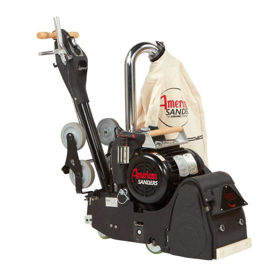
Introduction The American Legend can be used on a variety of wood types. It is an ideal tool for wood flooring maintenance and restoration work. It is not intended to be used on pressure treated wood, OSB, plywood or any other flooring type. Machine Specifications Part # 07236A / 07236B / 07236C... -
Page 8: Machine Transportation
Machine Transportation WARNING: The machine is heavy. Remove the motor from the AC Volt Meter Hour Meter Circuit Breaker machine before transporting. Get help loading the machine and motor. Use proper lifting techniques. Transporting the Machine - Using the Dolly Cart CAUTION: When deploying the dolly, the drum will contact the floor or ground over which the machine is resting. - Page 9 Figure 8 Figure 9 Figure 10 Transporting the Machine - Two Person NOTE: This is accomplished by removing the motor from the chassis and transporting the motor and chassis separately. To transport the machine, follow this procedure: 1. Make sure the power cable is disconnected from the machine. 2.
-
Page 10: Machine Setup
Machine Setup To set-up your machine, follow this procedure: 1. Familiarize yourself with the machine and read all danger, warning and caution statements. Make sure all operators of this machine have read this Operator’s Manual. If they cannot read this manual, have the manual explained fully before allowing anyone to operate the sander. - Page 11 Operating Instructions Sanding/finishing wood floors can create an DANGER: environment that can be explosive. Cigarette lighters, pilot lights and any other source of ignition can create an explosion when active during a sanding session. All sources of ignition should be extinguished or removed entirely if possible from the work area.
- Page 12 Operating Instructions 3. If the operating belt (American Sanders PN 53560A) is used, proceed as follows: a. Position the operating belt around waist. b. Cross the straps at the waist. (See figure 23) c. Slide the belt loop end over the handle on the control lever side.
-
Page 13: Tool And Accessories
Tool and Accessories Tools 1. Wrench-Paper Clamp Open End 7/16 & 9/16 (59810A) 2. Wrench – Open End 15/16 & 3/4 (60498A) 3. Hex Wrench “T” Handle 3/32 (51273A) 4. Hex Wrench right angle 7/32 (51274A) 5. Hex Wrench right angle 3/16 (AS036600) Accessories - Stair climber 1. -
Page 14: Sanding Cuts & Sandpaper
Sanding Cuts & Sandpaper Initial Cut The purpose of the initial cut is to remove old finish and gross imperfections on the floor surface. The sanding equipment should be adjusted to heavy sanding pressure setting and a coarse abrasive belt should be used. If the surface is severely damaged by deep scratches, preexisting dwell marks, uneven planks, etc., it may be necessary to sand across or diagonally to the grain to restore evenness to the surface. -
Page 15: Sander Adjustment Procedures
Sander Adjustment Procedures Electrocution could occur if maintenance and DANGER: repairs are performed on a unit that is not properly dis connected from the power source. Disconnect the power supply before attempting any maintenance or service. Moving parts of this machine can cause serious DANGER: injury and/or damage. -
Page 16: Leveling The Drum
Sander Adjustment Procedures Leveling the Drum The belt tracking maybe adversely effected if CAUTION: machine is operated unleveled. The machine is leveled at the factory set and no adjustments should be necessary. After any maintenance is performed to the carriage system, the pointer on the leveling bracket must be returned to original mark. -
Page 17: Routine Maintenance
Handle Height Adjustment 1. Remove power. 2. Lower the control lever. 3. Depress the button on the link rod. Twist outer tube to disengage. (See figure 42) 4. Loosen the handle lever on the front of the handle tube. (See figure 43) 5. -
Page 18: Troubleshooting
Troubleshooting Problem Cause Action Drive belts slip. Insufficient tension. Tension drive belt as described in (Squeaking or squealing sound) adjustment procedures. Worn belts. Replace belts. Squealing, growling or grinding noise Damaged and/or worn bearing. Remove drive belts, rotate arbor motor, fan, coming from machine. - Page 19 Troubleshooting Problem Cause Action Slow cutting. Dull abrasive. Replace abrasive. Too fine of an abrasive belt. Use a coarser abrasive belt. Insufficient sanding pressure. Increase sanding pressure setting. (Fig. #16, page 15). Waves on sanded surface. Debris on wheels. Remove and clean wheels. Flat spot on tire(s).
-
Page 21: Instructions De Sécurité De L'opérateur
LISEZ CE MANUEL Ce manuel contient des informations importantes relatives à l’utilisation et au fonctionnement sûr de cette machine. Si vous ne lisez pas ce manuel avant de faire fonctionner ou d'effectuer toute procédure d’entretien ou de maintenance à votre machine American Sanders, vous pourriez subir des blessures ou causer des blessures à autrui ; des dommages à la machine ou à... -
Page 22: Avertissements Généraux Sur La Sécurité Des Outils Électriques
DANGER : Si vous ne lisez pas le manuel d’utilisation avant de faire fonctionner ou d’effectuer toute procédure d’entretien à votre machine American Sanders, vous pourriez subir des blessures ou causer des blessures à autrui ; des dommages à la machine ou à d'autres biens pourraient également se produire. -
Page 23: Sécurité Personnelle
Ne pas exposer les outils électriques à la pluie ou à des conditions humides. L'eau qui pénètre dans un outil électrique augmente le risque de choc électrique. Ne pas abuser du cordon d’alimentation. Ne jamais utiliser le cordon pour transporter, tirer ou débrancher l'outil électrique. Tenir le cordon à... - Page 24 Ne pas utiliser des accessoires qui ne sont pas spécifiquement conçus et recommandés par le fabricant d'outils, Le simple fait que l’accessoire peut être attaché à votre outil électrique ne garantit pas un fonctionnement sûr. La vitesse nominale de l'accessoire doit être au moins égale à la vitesse maximale indiquée sur l'outil électrique. Les accessoires qui fonctionnent plus vite que leur vitesse nominale peuvent se briser et voler en éclats.
-
Page 25: Introduction
Introduction La machine American Legend peut être utilisée sur plusieurs types de bois. C'est un outil idéal pour les travaux d'entretien et de restauration des planchers en bois. Elle n’est pas destinée à être utilisée sur du bois traité sous pression, panneaux OSB, contreplaqués ou tout autre type de revêtement de sol. -
Page 26: Transport De La Machine
Transport de la machine AVERTISSEMENT : La machine est lourde. Retirez le moteur de la machine avant le transport. Demandez de l’aide pour le AC Volt Meter Hour Meter Circuit Breaker chargement de la machine et du moteur. Utilisez des techniques de levage appropriées. Transport de la machine - Utilisation du chariot roulant ATTENTION : Lors du déploiement du chariot, le tambour entre en... - Page 27 Figure 8 Figure 9 Figure 10 Transport de la machine - Deux personnes REMARQUE : Pour ce faire, retirez le moteur du châssis et transportez le moteur et le châssis séparément. Pour transporter la machine, procédez comme suit : 1. Assurez-vous que le câble d'alimentation est débranché de la machine. 2.
-
Page 28: Installation De La Machine
Installation de la machine Pour configurer votre machine, procédez comme suit : 1. Se familiariser avec la machine et lire tous les dangers, avertissements et mises en garde. S’assurer que tous les opérateurs de cette machine ont lu ce Manuel de l'opérateur. -
Page 29: Instructions D'exploitation
Instructions d'exploitation DANGER : Le ponçage/la finition des planchers en bois peut créer un environnement explosif. Les briquets, les voyants lumineux et toute autre source d'inflammation peuvent provoquer une explosion lorsqu'ils sont actifs pendant une séance de ponçage. Toutes les sources d’inflammation doivent être éteintes ou retirées entièrement, si possible, de la zone de travail. - Page 30 Instructions d'exploitation 3. Si la ceinture d’opération (American Sanders PN 53560A) est utilisée, procédez comme suit : Placez la ceinture d’opération autour de la taille. b. Croisez les bretelles à la taille. (Voir Figure 23). c. Faites glisser l'extrémité de la boucle de ceinture sur la poignée du côté du levier de commande.
-
Page 31: Outils Et Accessoires
Outils et accessoires Outils 1. Clé - Anneau de bride, extrémité ouverte 7/16 et 9/16 (59810A) 2. Clé – Extrémité ouverte 15/16 et 3/4 (60498A) 3. Clé hexagonale poignée en T 3/32 (51273A) 4. Clé hexagonale à angle droit 7/32 (51274A) 5. -
Page 32: Coupes De Ponçage Et Papier De Verre
Coupes de ponçage et papier de verre Coupe initiale Le but de la coupe initiale est d'éliminer les anciennes finitions et les imperfections brutes sur la surface du sol. L’équipement de ponçage doit être réglé à une pression de ponçage élevée et une courroie abrasive grossière doit être utilisée. Si la surface est gravement endommagée par des rayures profondes, des marques préexistantes, des planches irrégulières, etc., il peut être nécessaire de poncer en travers ou en diagonale par rapport au grain pour rétablir l'uniformité... -
Page 33: Procédures De Réglage De La Ponceuse
Procédures de réglage de la ponceuse DANGER : Une électrocution pourra se produire si l’entretien et les réparations sont effectuées sur un appareil qui n’est pas correctement dé- branché de la source d'alimentation. Débranchez l'alimentation électrique avant toute tentative de maintenance ou d’entretien. DANGER : Les pièces mobiles de cette machine peuvent entraîner des blessures graves et/ou des dommages. - Page 34 Procédures de réglage de la ponceuse Mise à niveau du tambour ATTENTION : Le déplacement de la courroie peut être affecté négativement si la machine est utilisée sans mise à niveau. La machine est mise à niveau en usine et aucun réglage ne doit être nécessaire. Après toute opération de maintenance sur le système de chariot, le pointeur sur le support de mise à...
-
Page 35: Maintenance Périodique
Réglage de la hauteur de la poignée 1. Coupez l'alimentation. 2. Abaissez le levier de commande. 3. Appuyez sur le bouton de la tige de liaison. Tournez le tube extérieur pour le désengager (Voir Figure 42). 4. Desserrez le levier de la poignée à l'avant du tube de la poignée. (Voir Figure 43). 5. -
Page 36: Dépannage
Dépannage Problème Cause Action Les courroies d'entraînement patinent. Tension insuffisante. Procédez à la tension la courroie d’entraîne- (Grincements ou crissements) ment comme décrit dans Courroies usées. les procédures de réglage. Remplacez les courroies. La machine émet un bruit de grincement Palier endommagé... - Page 37 Dépannage Problème Cause Action Coupe lente. Abrasif émoussé. Remplacez l'abrasif. Courroie abrasive trop fine. Utilisez une courroie abrasive plus Pression de ponçage insuffisante. grossière. Augmentez le réglage de la pression de ponçage. (Fig. #16, page 15). Vagues sur surface poncée. Débris sur les roues.
- Page 38 Legend FloorCrafter Belt Sander Parts Manual Notes: ________________________________________________ ________________________________________________ ________________________________________________ ________________________________________________ ________________________________________________ ________________________________________________ ________________________________________________ ________________________________________________ ________________________________________________ ________________________________________________ ________________________________________________ ________________________________________________ ________________________________________________ ________________________________________________ ________________________________________________ ________________________________________________ ________________________________________________ ________________________________________________ ________________________________________________ ________________________________________________ ________________________________________________ ________________________________________________ ________________________________________________ 38 52...
-
Page 39: Wiring Diagram
Wiring Diagram... -
Page 40: Base Assembly 1
Base Assembly 1 BASE ASSEMBLY 1 RF083100 052421 RF083100 052421... - Page 41 Base Assembly 1 Item Ref. No. Description Item Ref. No. Description 60392A BUMPER FRONT 52420A COVER LEVER 51219A RIVET, NYLON, CHRISTMAS 962870 SCR 3/8 -16X1 BT ST ALLEN TREE AS017200 BUMPER, CORNER 51215A BEARING FLANGE 5/8 X 1 X 1 56382754 BELT ABRASIVE 100 GRT AS044900...
-
Page 42: Ensemble De Base 2
Base Assembly 2 BASE ASSEMBLY 2 RF083200 022421 RF083200 022421... -
Page 43: Base Assembly 2
Base Assembly 2 Item Ref. No. Description Item Ref. No. Description AS037202 DOOR, DRUM, BLACK NB072400 SCREW, SET, 1/4-20 X 3/16" AS037205 DOOR, DRUM, RED 980652 WASHER, LOCK, 5/16 AS037206 DOOR, DRUM, BLUE NB025900 NUT, LOCK, 1/4", SS AS037207 DOOR, DRUM, GOLD NB6110 WASHER, LOCK, 1/4"... -
Page 44: Ensemble De Base 3
Base Assembly 3 BASE ASSEMBLY 3 RF083400 022421... -
Page 45: Base Assembly 3
Base Assembly 3 Item Ref. No. Description 962823 SCR 1/4-20 X 1/2 PN ST PH 10958A ROLLER ASM. 85303A SCREW, 8-32 X 3/8, PN ST PH AS059700 GASKET, LIGHT COVER 980657 WASHER, LOCK 1/4" 85700A SCREW, CAP, HH, 1/4-20 X 1 AS037302 COVER, LIGHT, BLACK AS037305... -
Page 46: Motor Assembly
MOTOR ASSEMBLY Motor Assembly RF082100 041621... - Page 47 Motor Assembly Item Ref. No. Description 962565 SCREW, 3/8-16, BT ST NC3 10173A ASSY MOTOR MOUNT 80138A NUT, JAM, 5/8-11 51222A SCREW, BELT TENSIONING 87034A RETAINER MOTOR PULLEY CLASSIC 8 962870 SCR 3/8 -16X1 BT ST ALLEN 60394A 57712A RING RETAINING MOTOR SHAFT 8 60498A WRENCH 15/16 X 3/4 OPEN 59810A...
-
Page 48: Capacitator Box Assembly
Capacitor Box Assembly CAPACITOR BOX ASSEMBLY 2200 RF082200 022421... - Page 49 Capacitor Box Assembly Item Ref. No. Description Item Ref. No. Description 41305A CAPACITOR ELECTR AS040900 GROMMET, 1/2 ID HEYCO 161-193MFD (PROVIDED WITH G1153 MOTOR) 980621 WASHER, LOCK, EXTERNAL TOOTH 41304A RUN CAPACITOR (PROVIDED WITH MOTOR) NB9725 NUT, LOCK, #8-32, NYLON 47378A SWITCH MOTOR STARTING AS064300...
-
Page 50: Belt Guard Assembly
BELT GUARD ASSEMBLY Belt Guard Assembly Dust Bag Assembly DUST BAG ASSEMBLY RF083300 022421 RF083300 022421 RF082700 022421 RF082700 022421... - Page 51 Belt Guard Assembly Item Ref. No. Description 81102A NUT STOP ELASTIC 1/4-20 HEX 920110 NUT, 5/16-18 HEX LOCK 80017A BOLT SHOULDER 3/8 X 2 3/4 NB030700 NUT, LOCK, 10-24, NYLON AS050600 BRACKET, PIN, LATCH 68393A TUBE LATCH PNTD8 BELT SANDER 85702A SCR 1/4-20 X 1 3/4 HX ST CAP AS037103...
-
Page 52: Handle Assembly Fixed
Handle Assembly Fixed HANDLE ASSEMBLY FIXED RF082600 022421 RF082600 022421... - Page 53 Handle Assembly Fixed Item Ref. No. Description Item Ref. No. Description AS052300 SWITCH, POWER 898203 SPACER ROD END HK-8 (07236A, 07236B, 07236C) 53537A ROD END 3/8-24 R.H. FEMALE 40775A SWITCH 16A 230/50 COIL (07241A, 07241B, 07241C) NB024500 SCREW, CAP, 3/8 X 1 3/4 AS052400 RECEPTACLE, USB 170883...
-
Page 54: Handle Assembly Adjustable
Handle Assembly Adjustable HANDLE ASSEMBLY ADJUSTABLE RF082000 022421 RF082000 022421... - Page 55 Handle Assembly Adjustable Item Ref. No. Description Item Ref. No. Description 980657 WASHER, LOCK 1/4" NB053900 SCREW, PAN HD, # 4-40 X 1/2" 80026A BOLT SHOULDER 3/8 X 1/2 NB007000 NUT, LOCK, NYLON, 4-40 980022 WASHER WAVE 962911 SCR 10-24X 1/2 BT SS ALLEN 87619A WASHER FLT .63X.38X.03 920204...
-
Page 56: Fan Cover Assembly
Fan Cover Assembly FAN COVER ASSEMBLY RF082300 022421 RF082300 022421... - Page 57 Fan Cover Assembly Item Ref. No. Description 60370A SHAFT FAN 877304 RING RETAINING INT., .918OD 23301A 61602A COLLAR 60414A ARM IDLER PNTD8 BELT SANDER 68010A STUD IDLER ARM8 BELT SANDER 67875A SPACER CLASSIC 8 57801A RING - SNAP 26 X 1.2 902619 BEARING 580/590 TB16 171101...
-
Page 58: Lift Handle Assembly
LIFT HANDLE ASSEMBLY Lift Handle Assembly LIFT HANDLE ASSEMBLY LIFT HANDLE ASSEMBLY LEVELING BRACKET ASSEMBLY LEVELING BRACKET ASSEMBLY LEVELING BRACKET ASSEMBLY Leveling Bracket Assembly PULL PIN ASSEMBLY Pull Pin Assembly PULL PIN ASSEMBLY PULL PIN ASSEMBLY RF082800 022421 RF082800 022421 RF082800 022421... - Page 59 Lift Handle Assembly Item Ref. No. Description AS049101 BRACKET, DETACHABLE HANDLE NB9470 NUT, ACORN, 3/8-16 UNC NB033200 SCREW, SOCKET, 10-24 X 3/4, FL NB030700 NUT, LOCK, 10-24, NYLON NB030100 WASHER, FLAT, #10, SS AS044700 LATCH, SPRING AS049000 SPACER, LATCH SPRING AS048800 GUARD, SPRING, LATCH AS048700...
-
Page 60: Belt Tensioner Assembly
Belt Tensioner Assembly BELT TENSIONER ASSEMBLY RF082400 022421 RF082400 022421... - Page 61 Belt Tensioner Assembly Item Ref. No. Description 747380 RING ROLLER RETAINING 902567 BEARING BALL DOUBLE SEALED 81217A NUT, 1/4-20 X .218H, NYLOK 60393A LEVER DRAW 962822 SCR 1/4-20 X 5/8 BT ST SOC 80139A SCREW, 1/4-20 X 7/8 BT 80020A BOLT SHOULDER 1/4 X 1 51211A E-RING .25 DIA...
-
Page 62: Control Carriage Assembly
Control Carriage Assembly CONTROL CARRIAGE ASSEMBLY RF082500 022421 RF082500 022421... - Page 63 Control Carriage Assembly Item Ref. No. Description 60397A COVER DUST THROAT 85517A SCREW #10-24 X 1/2 PHCR TYPE 23 81102A NUT STOP ELASTIC 1/4-20 HEX NB6530 SCREW, CAP, HH, 1/4-20 X 1 AS060900 CONTROL CARRIAGE, SPRING SUSP. 193944 GROMMETRUBBER 3/4ID X 3/8 980679 WASHER 3/4 SAE FLAT PLTD 962184...
-
Page 64: Transport Dolly Assembly
Transport Dolly Assembly TRANSPORT DOLLY ASSEMBLY RF083000 022421... - Page 65 Transport Dolly Assembly Item Ref. No. Description AS081800 DOLLY ASSEMBLY 39857A WHEEL 5 POLISHER NB025600 PIN, PRESTO, 3/32 X 1 5/8, SS 980648 WASH-17/32 ID X 1&1/16 OD PLN NB030700 NUT, LOCK, 10-24, NYLON NB049200 SCREW, BH, 10-24 X 5/8, SS AS064400 CATCH, WELDMENT, DOLLY AS056700...
-
Page 66: Motor Dolly Kit Assembly
Motor Dolly Kit Assembly MOTOR DOLLY KIT ASSEMBLY MOTOR DOLLY KIT ASSEMBLY STAIR CLIMBER KIT ASSEMBLY Stair Climber Kit Assembly STAIR CLIMBER KIT ASSEMBLY RF082900 022421 RF082900 022421 RF082900 022421... - Page 67 Motor Dolly Kit Assembly Item Ref. No. Description AS081400 MOTOR DOLLY, KIT AS046300 CARRIAGE, MOTOR, WELDMENT NB044500 SCREW, SOCKET, FLAT, C/S, 3/8-16 X 1" MP366900 GRIP, HANDLE, 7/8", BLK 920248 NUT 3/8-16 ESNA LIGHT AS045000 STUD, KEYHOLE Stair Climber Kit Assembly Item Ref.
- Page 69 Limited Warranty Legend TO QUALIFY FOR THIS WARRANTY INSTRUCTIONS AND CONDITIONS FOR WARRANTY REIMBURSEMENT (1) Machine must be registered within 30 days from the time of purchase on a form provided by American Sanders. Your Order replacement part: Orders will be processed and charged, American Sanders Distributor is responsible for the registration as normal procedure.
- Page 72 American Sanders an AMANO Company 1 Eclipse Rd l PO Box 909 Sparta, North Carolina 28675 l USA www.pioneereclipse.com www.americansanders.com +1-336-372-8080 1-800-367-3550 Fax 1-336-372-2913 LT080100 © 2021 American Sanders Legend_D 052621...