Table des Matières
Publicité
Les langues disponibles
Les langues disponibles
Liens rapides
3B SCIENTIFIC ® PHYSICS
Mikrowellensatz 9,4 GHz (230 V, 50/60 Hz)
Mikrowellensatz 10,5 GHz (115 V, 50/60 Hz)
1009951 / U8493600-230
1009950 / U8493600-115
Bedienungsanleitung
08/11 ERL/ALF
Betriebsgerät
1
2
3
4
5
6
7
8
9
10 Buchse für Steckernetzgerät 12 V
Zubehör
11 Sender mit Hornantenne
12 Auflageplatte für Prisma
13 Prisma aus Paraffin
14 Reflektorplatte
15 Abdeckplatte für Doppelspalt
16 Platte mit Doppelspalt
17 Absorptionsplatte
18 Polarisationsgitter
19 Empfänger mit Hornantenne
20 Mikrowellenbank
21 Mikrowellensonde
22 Mikrowellen-Gelenkbank mit
1
Anschluss für Empfänger
Verstärkerausgang
Verstärkerausgang (Masse)
Anschluss für Sender
Modulationseingang (Masse)
Modulationseingang
Wahlschalter für Modulation
(intern/off/extern),
Schalter für internen Lautsprecher
Regler für Signalverstärkung
Empfänger
AC (Gehäuserückseite)
Plattenhalter
Publicité
Table des Matières

Manuels Connexes pour 3B SCIENTIFIC PHYSICS U8493600-230


Sommaire des Matières pour 3B SCIENTIFIC PHYSICS U8493600-230
- Page 1 3B SCIENTIFIC ® PHYSICS Mikrowellensatz 9,4 GHz (230 V, 50/60 Hz) Mikrowellensatz 10,5 GHz (115 V, 50/60 Hz) 1009951 / U8493600-230 1009950 / U8493600-115 Bedienungsanleitung 08/11 ERL/ALF Betriebsgerät Anschluss für Empfänger Verstärkerausgang Verstärkerausgang (Masse) Anschluss für Sender Modulationseingang (Masse) Modulationseingang Wahlschalter für Modulation...
- Page 2 1 Prisma aus Paraffin 1. Sicherheitshinweise 1 Auflageplatte für Prisma HF-Felder können in biologisches Gewebe eindringen 1 Platte mit Doppelspalt und dieses erwärmen. Der enthaltene Mikrowellen- 1 Abdeckplatte für Doppelspalt sender ist so leistungsschwach, dass Gefährdungen bei sachgemäßem Betrieb des Gerätes nicht auftre- 1 Bedienungsanleitung ten.
- Page 3 • Lautsprecher mit Schalter (8) einschalten. dem Pegel und der Verstärkung proportionale Gleichspannung, die z.B. über ein Zeigerinstrument • Modulator mit Schalter (7) auf „INT“ schalten. (z.B. Analogmultimeter AM50 1003073 / U17450) Das abgestrahlte Mikrowellensignal wird rechteck- angezeigt werden kann. förmig moduliert, die Modulationsfrequenz kann Wird mit Schalter (7) die Stellung „EXT“...
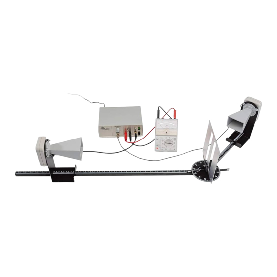
- Page 4 6.4 Reflexion • Grundeinstellung vornehmen (5.1). • Reflektorplatte im Winkel von ca. 30°, 40°, 50°, 60° mittels Zeigerschiene einstellen; Zei- ger weist in Richtung Einfallslot. • Winkel der langen Schiene ändern, bis maxi- maler Empfang auftritt. • Winkelmessung vom Lot weg durchführen (Pfeil).
- Page 5 6.7 Huygenssches Prinzip • Sender (11) ca. 20 cm vom Plattenhalter ent- fernt und Empfänger (19) in einem Abstand von ca. 80 cm vom Plattenhalter auf die Schienen setzen. • Empfänger mittels Schiene auf einer Kreisbahn so weit aus Wellenbündel heraus bewegen, bis das Signal deutlich abgeschwächt ist.
- Page 6 6.10 Polarisation • Polarisationsgitter (18) im Plattenhalter ein- spannen. • Empfangsmöglichkeit bei horizontaler Ausrich- tung des Polarisationsgitters überprüfen. • Empfangsmöglichkeit bei vertikaler Ausrich- tung des Polarisationsgitters überprüfen. Folgerung: Da einmal ein Empfang nachgewiesen wird und bei Drehung um 90° kein Signal den Empfänger erreicht, wird demonstriert, dass die Hornantenne ein Wechselfeld erzeugt, das nur in einer Richtung schwingt, also polarisiert ist.
-
Page 7: Instruction Sheet
3B SCIENTIFIC ® PHYSICS Microwave Set 9.4 GHz (230 V, 50/60 Hz) Microwave Set 10.5 GHz (115 V, 50/60 Hz) 1009951 / U8493600-230 1009950 / U8493600-115 Instruction sheet 08/11 ERL/ALF Control unit Receiver terminal Amplifier output Amplifier output (ground) Transmitter terminal... -
Page 8: System Setup
1 Polarisation grating, 180 x 180 mm² 1. Safety instructions 1 Absorption plate, fibreboard, 180 x 180 mm² High frequency radio waves can penetrate biological 1 Paraffin prism tissues and cause them to heat up. The microwave 1 Stand for prism transmitter included here is sufficiently low-powered that the hazards are negligible when it is used cor- 1 Plate with double slit... - Page 9 • Use switch (7) to send the modulator to “INT”. This can, for example, be displayed using an instru- ment with a dial (e.g. AM50 analog multimeter The microwave signal emitted is modulated with a 1003073/U17450). square wave. The modulation frequency can be lis- tened to by means of the built-in speaker.
- Page 10 6.4 Reflection • Set up the basic configuration (5.1). • Line up the reflector plate at angles of ap- proximately 30°, 40°, 50° and 60° with the help of the pointer for the rails, which points in the direction of the normal (a line perpen- dicular to the mirror’s surface).
- Page 11 6.7 Huygens’ principle • Set up the transmitter (11) about 20 cm from the plate holder and the receiver (19) about 80 cm behind the late holder on the rails. • Turn the receiver around on its rail so that it is out of the bundled microwave beam and the signal is clearly weakened.
- Page 12 6.10 Polarisation • Set up the polarisation grating (18) in the screen holder. • Check the reception when the polarisation grating is aligned horizontally. • Check the reception when the polarisation grating is aligned vertically. Conclusion: Since in one state a signal is received but when the grating is rotated 90°...
-
Page 13: Scientific ® Physique
3B SCIENTIFIC ® PHYSIQUE Kit micro-ondes 9,4 GHz (230 V, 50/60 Hz) Kit micro-ondes 10,5 GHz (115 V, 50/60 Hz) 1009951 / U8493600-230 1009950 / U8493600-115 Instructions d’utilisation 08/11 ERL/ALF Unité de contrôle Connexion pour récepteur Sortie d'amplificateur Sortie d'amplificateur (masse) Connexion pour émetteur... -
Page 14: Montage Du Système De Rail (Réglage De Base)
1 Plaque de réflexion, 180 x 180 mm² 1. Consignes de sécurité 1 Grille de polarisation, 180 x 180 mm² Les champs HF peuvent pénétrer dans les tissus bio- 1 Plaque d'absorption, matière fibreuse, 180x180 mm² logiques et les réchauffer. L'émetteur à micro-ondes 1 Prisme en paraffine est si faible qu'il ne peut en émaner aucun risque si l'appareil est utilisé... -
Page 15: Propagation Rectiligne Des Micro-Ondes
• Régler le volume sur la position intermédiaire à La modulation est désactivée par la position centrale l'aide du régulateur d'amplification du signal (9). de l'interrupteur (7). Une tension continue propor- tionnelle au niveau et à l'amplification, arrive au • Mettre le haut-parleur en marche à... - Page 16 6.4 Réflexion • Effectuer le réglage de base (5.1). • Ajuster la plaque de réflexion dans un angle d’environ 30°, 40°, 50°, 60° au moyen de l’aiguille. • Modifier l’angle du rail long jusqu’à obtenir la réception maximum. Mesure de l’angle (par l’aiguille). Conclusion : Les micro-ondes sont réfléchies sur les conducteurs électriques.
- Page 17 6.7 Principe de Huyegens • Placer l'émetteur (11) à env. 20 cm du support de plaque et le récepteur (19) à une distance d'env. 80 cm du support de plaque, sur les rails. • Déplacer le récepteur au moyen du banc de guidage sur le périmètre jusqu’à...
-
Page 18: Transmission D'informations
6.10 Polarisation • Placez la grille de polarisation (18) dans le porte-plaque. • Vérifiez la réception lorsque la grille de polari- sation est ajustée verticalement. • Vérifiez la réception lorsque la grille de polari- sation est ajustée horizontalement. Conclusion : Comme une seule des deux combinai- sons permet une réception du signal, il est démon- tré... - Page 19 3B SCIENTIFIC ® PHYSICS Set microonde 9,4 GHz (230 V, 50/60 Hz) Set microonde 10,5 GHz (115 V, 50/60 Hz) 1009951 / U8493600-230 1009950 / U8493600-115 Istruzioni per l'uso 08/11 ERL/ALF Apparecchio base Collegamento per ricevitore Uscita amplificatore Uscita amplificatore (massa)
-
Page 20: Struttura Del Sistema
1 Piastra del riflettore 180 x 180 mm² 1. Norme di sicurezza 1 Griglia di polarizzazione, 180 x 180 mm² I campi ad alta frequenza possono penetrare nei 1 Piastra di assorbimento in fibra, 180 x 180 mm² tessuti biologici e riscaldarli. Il trasmettitore a 1 Prisma in paraffina microonde contenuto nell'apparecchio presenta una potenza talmente ridotta da non rappresentare un... - Page 21 • Disporre trasmettitore e ricevitore sul sistema di Nella posizione centrale dell'interruttore (7), la guide come indicato nelle figure relative agli modulazione è disattivata. Sulla coppia di jack (3)(4) esperimenti. è presente una tensione continua proporzionale al livello e all'amplificazione, visualizzabile per mezzo •...
- Page 22 6.4 Riflessione • Effettuare una regolazione di base (5.1). • Regolare la piastra del riflettore con un angolo di ca. 30°, 40°, 50°, 60° mediante la guida del puntatore; il puntatore è rivolto verso la perpendicolare incidente. • Modificare l'angolo della guida lunga, fino ad ottenere la ricezione massima.
- Page 23 6.7 Principio di Huygens • Disporre sulle guide il trasmettitore (11) e il ricevitore (19), osservando una distanza dal supporto della piastra pari a circa 20 cm per il primo e 80 cm per il secondo. • Allontanare il ricevitore tramite la guida su binario circolare ad una distanza tale dal fascio di onde per cui il segnale risulta nettamente indebolito.
- Page 24 6.10 Polarizzazione • Montare la griglia di polarizzazione (18) nel supporto della piastra. • Verificare la possibilità di ricezione orientando la griglia in orizzontale. • Verificare la possibilità di ricezione orientando la griglia in verticale. Conclusione: poiché una volta si ottiene la ricezione poi, ruotando la griglia di 90°, il ricevitore non riceve alcun segnale, si può...
- Page 25 3B SCIENTIFIC ® PHYSICS Equipo de microondas 9,4 GHz (230 V, 50/60 Hz) Equipo de microondas 10,5 GHz (115 V, 50/60 Hz) 1009951 / U8493600-230 1009950 / U8493600-115 Instrucciones de uso 08/11 ERL/ALF Aparato de trabajo Conexión para el receptor...
-
Page 26: Montaje Del Sistema
1 Banco de microondas articulado, 400 mm con 1. Advertencias de seguridad portaplacas Campos electromagnéticos de AF pueden penetrar 1 Placa reflectora 180 x 180 mm² en el tejido biológico y producir recalentamiento. El 1 Rejilla de polarización, 180 x 180 mm² emisor de microondas incorporado es de baja poten- 1 Placa de absorción de material fibroso, 180 x 180 mm²... - Page 27 resp. la sonda receptora en el punto de conexión La modulación de desactiva en la posición central para el receptor (1). del conmutador (7). En el par de casquillos (3) y (4) se tiene una tensión continua proporcional al nivel de •...
- Page 28 6.3 Apantallamiento y absorción • Placa reflectora (12) se coloca en el portapla- cas entre el emisor y el receptor (conductor eléctrico). • La amplificación se ajusta en la gama inferior. • Conclusión: Conductores eléctricos apantallan las microondas (placa metálica), porque no se puede detectar una señal de recepción.
- Page 29 6.6 Refracción • Realice el ajuste básico (5.1). • La placa soporte para el prisma (10) se inserta en el lado opuesto a la flecha. • Se coloca el prisma (11) sobre la placa soporte y se orienta. • Se gira la guía larga axialmente hasta que se obtenga la máxima recepción.
- Page 30 6.10 Polarización • Se enclava la rejilla de polarización en el porta- placas. • Se comprueba la posibilidad de recepción con la rejilla de polarización orientada horizontal- mente. • Se comprueba la posibilidad de recepción con la rejilla de polarización orientada vertical- mente.
-
Page 31: Instruções De Operação
3B SCIENTIFIC ® PHYSICS Conjunto para microondas 9,4 GHz (230 V, 50/60 Hz) Conjunto para microondas 10,5 GHz (115 V, 50/60 Hz) 1009951 / U8493600-230 1009950 / U8493600-115 Instruções de operação 08/11 ERL/ALF Aparelho operacional Conexão receptor Saída do amplificador Saída do amplificador (massa) -
Page 32: Montagem Do Sistema
1 Placa do refletor 180 x 180 mm² 1. Indicações de segurança 1 grade de polarização, 180 x 180 mm² Campos de AF podem penetrar o tecido biológico e 1 placa de absorção de tecido de fibras, 180 x 180 mm² aquecê-lo. - Page 33 conector para o emissor (4). A modulação é desativada com o posicionamento médio do comutador (7). No par de tomadas (3)(4) • Colocar o volume de som com o regulador para encontra-se uma tensão contínua proporcional ao a potência de sinal (9) sobre a posição do médio. prumo e da amplificação, que pode ser exibida, por •...
- Page 34 6.4 Reflexão • Efetuar ajustes básicos (5.1). • Ajustar a placa do refletor em ângulo de aprox. 30°, 40°, 50°, 60° por meio do trilho indicador; O indicador indica em direção do prumo de incidência. • Alterar o ângulo do trilho longo até atingir a recepção máxima.
- Page 35 6.7 Principio de Huygens • Colocar o emissor (11) aprox. 20 cm distante do suporte de placa e o receptor (19) numa distância de aprox. 80 cm do suporte de placa sobre o trilho. • Por meio do trilho sobre a órbita mover o emissor tanto para fora do feixe de ondas até...
- Page 36 6.10 Polarização • Fixar a grade de polarização (16) no suporte de placa. • Verificar a possibilidade de recepção em posição horizontal da grade de polarização. • Verificar a possibilidade de recepção em posição vertical da grade de polarização. Conclusão: sendo que já foi comprovada uma recepção e ao girar 90°...