Publicité

Les langues disponibles

Les langues disponibles

Liens rapides

Installation Manual of Room Air Conditioner
Preparation
Necessary Tools for Installation
Hammer
Nipper
Hacksaw
Hole core drill
Spanner(17,19 and 26mm)
Gas leakage detector or
soap-and-water solution
Power Source
Before inserting power plug into receptacle, check the voltage without fail.
The power source is the same as the corresponding name plate.
Install an exclusive branch circuit of the power.
A receptacle shall be set up in a distance where the power cable can be
reached.Do not extend the cable by cutting it.
Drawing for the installation of indoor and outdoor units
The models adopt HC FC free refrigerant R410A
more than 5cm
more than
10cm
Arrangement of piping
directions
Rear left
Rear
Left
right
Right
Below
more than 10cm
The marks from
to
A
in the figure are the
G
parts numbers.
The distance between
the indoor unit and the
floor should be more
than 2m.
more than 60cm
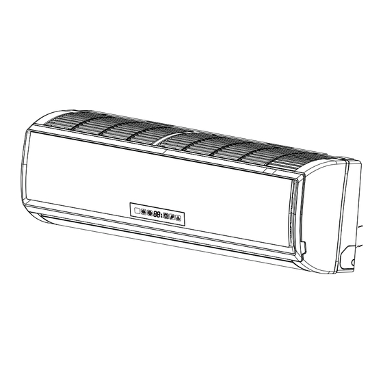
The above picture is for your reference only. Your product may look different.
Read this manual before installation.
Explain the operation or the unit to the user according to this manual.
NO.0010526879
Torque wrench
(17mm,22mm,26mm)
Pipe cutter
Flaring tool
Knife
Measuring tape
Reamer
Attention must be paid to
the rising up of drain hose
more than 10cm
more than
10cm
Selection of Installation Place
Indoor Unit - Select a plocation that is
Robust not causing vibration, where the body can be supported sufficiently.
Not affected by heat or steam generated in the vicinity, where inlet and outlet of the
unit are not disturbed.
Possible to drain easily, where piping can be connected with the outdoor unit.
Where cold air can be spread in a room evenly.
Nearby a power receptacle. (Refer to drawings).
Place where the distance of more than lm from televisions, radios, wireless apparatuses
and fluorescent lamps can be left.
In the case of fixing the remote controller on a wall, place where the indoor unit can
receive signals when the fluorescent lamps in the room are lightened.
Outdoor Unit - Select a plocation that is
Not less affected by rain or direct sunlight and is sufficiently ventilated.
Strong enough to bear the unit, where vibration and noise are not increased.
Place, where discharged wind and noise do not cause a nuisance to the neighbors.
Place, where a distance marked
G
F
Floor fixing dimensions of the
A
outdoor unit (Unit:mm)
C
Fixing of outdoor unit
D
E
more than15cm
is available as illustrated in the above figure.
Optional parts for piping
Non-adhesive tape
A
Adhesive tape
B
Saddle (L.S) with screws
C
Connecting electric cable
D
for indoor and outdoor
E
Drain hose
F
Heating insulating material
Piping hole cover
G
Fix the unit to concrete or block
with bolts (10mm) and nuts firmly
and horizontally.
When fitting the unit to wall
surface, roof or rooftop, fix
a supporter securely with nails
or wires in consideration of
earthquake and strong wind.
If vibration may affect the
house, fix the unit by attaching a
vibration-proof mat.

Publicité

Table des Matières
loading

Sommaire des Matières pour Haier HSU09VHJDBW

  • Page 1 Installation Manual of Room Air Conditioner Preparation Selection of Installation Place Necessary Tools for Installation Indoor Unit - Select a plocation that is Torque wrench Hammer (17mm,22mm,26mm) Nipper Robust not causing vibration, where the body can be supported sufficiently. Hacksaw Pipe cutter Not affected by heat or steam generated in the vicinity, where inlet and outlet of the Hole core drill...
  • Page 2: Indoor Unit

    1. Insert the drain hose into the dent of heat insulation materials of indoor unit. Accessory parts 2. Insert the indoor/outdoor electric cable from backside of indoor unit, and pull it out on the front side, then connect them. Drain hose (1) 3.
  • Page 3 Ensure that on dirt or debris enters the pipe. Outdoor unit The standard pipe length is 5m. If it is over 7m, the function of the unit will be affected. If the pipe has to be lengthened, the refrigerant should be charged, according to 20 g/m.
  • Page 4 No gas leakage? On Drainage In case of gas leakage, tighten parts of pipe connection. If leakage stops, then proceed 6. steps Please install the drain hose so as to be downward slope without fail. Please don’t do the drainage as shown below. If it does not stop gas leakage, discharge whole refrigerants from the service port.
  • Page 5 Manual de instalación de aparato de aire acondicionado Preparación Herramientas necesarias para realizar la instalación Selección del lugar de instalación Unidad interior – Elija una ubicación que sea Firme y que no provoque Martillo Llave dinamométrica (17mm, 22mm, vibraciones, que pueda soportar la unidad adecuadamente. 26mm) Que no se vea afectada por calor o vapor generado en las cercanías y donde las Alicate...
  • Page 6 1. Pase la manguera aislante a través del hueco de los materiales de aislamiento Accesorios de calor de la unidad interior. 2. Inserte los cables eléctricos de interior / exterior a través de la parte trasera de la unidad interior y tire de ellos desde la parte delantera. A continuación, conéctelos. Manguera de Control remoto (1) 3.
  • Page 7 Asegúrese de que no penetren residuos o suciedad en el tubo. Unidad exterior La longitud estándar del tubo es de 5m. Si el tubo tiene más de 7m, se verán afectadas las funciones de la unidad. Si es necesario alargar el tubo, deberá cargarse refrigerante adicional a razón de 20 g/m.
  • Page 8 5. ¿No existen fugas de gas? Durante el drenaje En caso de que exista una fuga de gas, apriete las conexiones de los tubos. Si la fuga se detiene, proceda al paso 6. Instale la manguera de drenaje formando una pendiente descendiente. No practique el drenaje como se muestra a continuación.
  • Page 9 Manuel d'installation d'un climatiseur de pièce Préparation Outillage requis pour l'installation Sélection de l'emplacement pour l'installation Unité intérieure – Sélectionnez un emplacement qui soit Marteau Clé dynamométrique (17 mm, 22 mm, Solide sans vibration et offrant un support suffisant. 26 mm) N'est pas affecté...
  • Page 10 1. Insérez le flexible d'évacuation dans l'encoche des matériaux d'isolation thermique Accessoires de l'unité intérieure. 2. Introduisez le câble électrique de l'unité intérieure/extérieure de l'endos de l'unité intérieure et sortez-le par l'avant puis effectuez la connexion. Télécommande (1) Tuyau de vidange (1) 3.
  • Page 11 Assurez-vous qu'aucune impureté ni débris ne sont entrés dans le tuyau. La longueur standard du tuyau est de 5 m. Au delà de 7 m, l'unité ne fonctionnera pas Unité extérieure correctement. S'il faut rallonger le tuyau, le réfrigérant doit être chargé selon 20 g/m. Toutefois, la charge de réfrigérant doit être exécuté...
  • Page 12 5. Pas de fuite de gaz? Vidange En cas de fuite de gaz, resserrez les pièces de connexion du tuyau. Lorsque la fuite est maîtrisée, passez à l'étape 6 Installez le tuyau de vidange de manière à ce que la pente soit descendante. Ne pas effectuer la vidange telle qu'illustrée ci-dessous.
  • Page 13 Installation Manual of Room Air Conditioner Preparation Selection of Installation Place Necessary Tools for Installation Indoor Unit - Select a location that is Torque wrench Hammer (17mm,22mm,26mm) Nipper Robust not causing vibration, where the body can be supported sufficiently. Hacksaw Pipe cutter Not affected by heat or steam generated in the vicinity, where inlet and outlet of the Hole core drill...
  • Page 14 · [ Left Left-rear piping ] Accessory parts In case of left side piping, cut away, with a nipper, the lid for left piping. In case of left-rear piping, bend the pipes according to the piping direction to Drain hose (1) Remote controller (1) the mark of hole for left-rear piping which is marked on heat insulation materials.
  • Page 15: Outdoor Unit

    Ensure that no dirt or debris enters the pipe. Outdoor unit The standard pipe length is 7m (27 9/16) . If it is over 7m (27 9/16) , the function of the unit will be affected. If the pipe has to be lengthened, the refrigerant should Indoor uni t be charged, according to 20 g/m (0.018 oz/inch).
  • Page 16 No gas leakage? On Drainage In case of gas leakage, tighten parts of pipe connection. If leakage stops, Please install the drain hose so as to be downward slope without fail. then proceed step 6. If leak continues, remove the refrigerant used for the Please don’t do the drainage as shown below.
  • Page 17: Fuente De Alimentación

    Manual de instalación de aparato de aire acondicionado Preparación Herramientas necesarias para realizar la instalación Selección del lugar de instalación Unidad interior – Elija una ubicación que sea Martillo Llave dinamométrica (17 mm, 22 mm, 26 mm) ● Firme y que no provoque vibraciones, que pueda soportar la unidad adecuadamente. Alicate ●...
  • Page 18: Unidad Interior

    [Izquierda • Entubación trasera izquierda] Accesorios En caso de realizar la entubación por el lado izquierdo, corte con una cuchilla la cubierta de la entubación izquierda. En caso de realizar la entubación a través de la parte trasera izquierda, doble los Control remoto (1) Manguera de drenaje (1) tubos de acuerdo con la dirección de entubación que figura en la marca del orificio...
  • Page 19: Unidad Exterior

    Asegúrese de que no penetren residuos o suciedad en el tubo. Unidad exterior La longitud estándar del tubo es de 7m . Si el tubo tiene más de 7m (27 9/16) (27 9/16) se verán afectadas las funciones de la unidad. Si es necesario alargar el tubo, deberá Unidad interior cargarse refrigerante adicional a razón de 20 g/m (0.018 oz/pulgada)
  • Page 20 5. ¿No existen fugas de gas? 1. Cortar el tubo 2. Eliminar las rebabas Cuchilla de conicidad En caso de que exista una fuga de gas, apriete las conexiones de los tubos. Si la fuga se detiene, proceda al paso 6. 3.
  • Page 21: Préparation

    Manuel d'installation d'un climatiseur de pièce Préparation Outillage requis pour l'installation Sélection de l'emplacement pour l'installation Unité intérieure – Sélectionnez un emplacement qui soit Marteau Clé dynamométrique (17 mm, 22 mm, 26 mm) Pince ● Solide sans vibration et offrant un support suffisant. ●...
  • Page 22: Accessoires

    Accessoires [Gauche • Tuyauterie arrière gauche] Dans le cas d'une tuyauterie à gauche, découpez, avec une pince, le couvercle pour la tuyauterie gauche. Télécommande (1) Tuyau de vidange (1) Pour une tuyauterie à l'arrière gauche, cintrez les tuyaux selon le sens de la tuyau- terie jusqu'à...
  • Page 23: Unité Extérieure

    Assurez-vous qu'aucune impureté ni débris ne sont entrés dans le tuyau. Unité extérieure La longueur standard du tuyau est de 7 m . Au delà de 7 m , l'unité (27 9/16) (27 9/16) ne fonctionnera pas correctement. S'il faut rallonger le tuyau, le réfrigérant doit être chargé...
  • Page 24 5. Pas de fuite de gaz? Correct Incorrect En cas de fuite de gaz, resserrez les pièces de connexion du tuyau. Lorsque la fuite est maîtrisée, passez à l'étape 6 Insuffisant Evasement endommagé Fissure Partiel Vers extérieur Vidange 6. Détachez le tuyau de charge de l'orifice d'entretien, ouvrez la vanne à 2 et 3 voies. Tournez le robinet de la vanne dans le sens antihoraire.
  • Page 25 Installation Manual of Room Air Conditioner Preparation Selection of Installation Place Necessary Tools for Installation Indoor Unit - Select a location that is Torque wrench Hammer (17mm,22mm,26mm) Nipper Robust not causing vibration, where the body can be supported sufficiently. Hacksaw Pipe cutter Not affected by heat or steam generated in the vicinity, where inlet and outlet of the Hole core drill...
  • Page 26 · [ Left Left-rear piping ] Accessory parts In case of left side piping, cut away, with a nipper, the lid for left piping. In case of left-rear piping, bend the pipes according to the piping direction to Drain hose (1) Remote controller (1) the mark of hole for left-rear piping which is marked on heat insulation materials.
  • Page 27 Outdoor unit Outdoor unit Indoor uni t Installation of Outdoor Unit Drawing for the installation of indoor and outdoor units Install according to 4wire 14AWG Control Wiring Connection of pipes To bend a pipe, be careful not to crush the pipe, and the bending radius should be 30 (1 1/6) to 40 mm (1 4/7) or longer.
  • Page 28 1.Cut pipe 2.Remove burs Flare tooling die Purging Method:To use vacuum pump Remove the service port cap of the 3-way valve and the valve stem cap for both valves. Connect the low pressure hose from the manifold set to the 3-way valve. 4.Flare pipe Connect the center hose to the vacuum pump.
  • Page 29 Manual de instalación de aparato de aire acondicionado Preparación Herramientas necesarias para realizar la instalación Selección del lugar de instalación Unidad interior – Elija una ubicación que sea Martillo Llave dinamométrica (17 mm, 22 mm, 26 mm) ● Firme y que no provoque vibraciones, que pueda soportar la unidad adecuadamente. Alicate ●...
  • Page 30 [Izquierda • Entubación trasera izquierda] Accesorios En caso de realizar la entubación por el lado izquierdo, corte con una cuchilla la cubierta de la entubación izquierda. En caso de realizar la entubación a través de la parte trasera izquierda, doble los Control remoto (1) Manguera de drenaje (1) tubos de acuerdo con la dirección de entubación que figura en la marca del orificio...
  • Page 31 Unidad exterior Unidad exterior Unidad interior Instalación de la unidad exterior Instale la unidad exterior de acuerdo con el diagrama de instalación de unidades 4 hios 18AWG interiores y exteriores. control de dos hilos Conexión de los tubos Para doblar un tubo, intente hacer la curva lo más suave posible para no aplastar el Cableado de tubo.
  • Page 32 1. Cortar el tubo 2. Eliminar las rebabas Cuchilla de conicidad Método de purga: para utilizar una bomba de vacío 1. Retire el tapón del puerto de mantenimiento de la válvula de 3 vías, el tapón del vástago de la válvula de 2 vías y 3 vías, y conecte el puerto de mantenimiento a la manguera de proyección de carga (inferior) del colector.
  • Page 33 Manuel d'installation d'un climatiseur de pièce Préparation Outillage requis pour l'installation Sélection de l'emplacement pour l'installation Unité intérieure – Sélectionnez un emplacement qui soit Marteau Clé dynamométrique (17 mm, 22 mm, 26 mm) Pince ● Solide sans vibration et offrant un support suffisant. ●...
  • Page 34 Accessoires [Gauche • Tuyauterie arrière gauche] Dans le cas d'une tuyauterie à gauche, découpez, avec une pince, le couvercle pour la tuyauterie gauche. Télécommande (1) Tuyau de vidange (1) Pour une tuyauterie à l'arrière gauche, cintrez les tuyaux selon le sens de la tuyau- terie jusqu'à...
  • Page 35 Unité extérieure Unité extérieure Unité intérieure Installation de l’unité extérieure 4 fils 18AWG Effectuez l'installation selon le schéma d'installation des unités intérieures et extérieures câble de commande Raccords de tuyauterie Câblage d’alimentation Lorsque vous cintrez un tuyau, prenez soin de ne pas écraser le tuyau. Le rayon de cintrage doit être entre 30 (1 1/6) et 40...
  • Page 36 Matrice de l'outillage 1.Coupez le tuyau 2. Nettoyez les ébavures d'évasement Méthode de purge: avec une pompe à vide: 1. Enlevez le capuchon de l'orifice d'entretien de la vanne à 3 voies, le capuchon du robinet de la vanne à 2 voies et à 3 voies. Connectez ensuite l'orifice d'entre- 4.
  • Page 37 Installation Manual of Room Air Conditioner Preparation Selection of Installation Place Necessary Tools for Installation Indoor Unit - Select a location that is Torque wrench Hammer (17mm,22mm,26mm) Nipper Robust not causing vibration, where the body can be supported sufficiently. Hacksaw Pipe cutter Not affected by heat or steam generated in the vicinity, where inlet and outlet of the Hole core drill...
  • Page 38 · [ Left Left-rear piping ] Accessory parts In case of left side piping, cut away, with a nipper, the lid for left piping. In case of left-rear piping, bend the pipes according to the piping direction to Drain hose (1) Remote controller (1) the mark of hole for left-rear piping which is marked on heat insulation materials.
  • Page 39 Outdoor unit Outdoor unit Indoor uni t Installation of Outdoor Unit Drawing for the installation of indoor and outdoor units Install according to 4wire 14AWG Control Wiring Connection of pipes To bend a pipe, be careful not to crush the pipe, and the bending radius should be 30 (1 1/6) to 40 mm (1 4/7) or longer.
  • Page 40 1.Cut pipe 2.Remove burs Flare tooling die Purging Method:To use vacuum pump Remove the service port cap of the 3-way valve and the valve stem cap for both valves. Connect the low pressure hose from the manifold set to the 3-way valve. 4.Flare pipe Connect the center hose to the vacuum pump.
  • Page 41 Manual de instalación de aparato de aire acondicionado Preparación Herramientas necesarias para realizar la instalación Selección del lugar de instalación Unidad interior – Elija una ubicación que sea Martillo Llave dinamométrica (17 mm, 22 mm, 26 mm) ● Firme y que no provoque vibraciones, que pueda soportar la unidad adecuadamente. Alicate ●...
  • Page 42 [Izquierda • Entubación trasera izquierda] Accesorios En caso de realizar la entubación por el lado izquierdo, corte con una cuchilla la cubierta de la entubación izquierda. En caso de realizar la entubación a través de la parte trasera izquierda, doble los Control remoto (1) Manguera de drenaje (1) tubos de acuerdo con la dirección de entubación que figura en la marca del orificio...
  • Page 43 Unidad exterior Unidad exterior Unidad interior Instalación de la unidad exterior Instale la unidad exterior de acuerdo con el diagrama de instalación de unidades 4 hios 18AWG interiores y exteriores. control de dos hilos Conexión de los tubos Para doblar un tubo, intente hacer la curva lo más suave posible para no aplastar el Cableado de tubo.
  • Page 44 1. Cortar el tubo 2. Eliminar las rebabas Cuchilla de conicidad Método de purga: para utilizar una bomba de vacío 1. Retire el tapón del puerto de mantenimiento de la válvula de 3 vías, el tapón del vástago de la válvula de 2 vías y 3 vías, y conecte el puerto de mantenimiento a la manguera de proyección de carga (inferior) del colector.
  • Page 45 Manuel d'installation d'un climatiseur de pièce Préparation Outillage requis pour l'installation Sélection de l'emplacement pour l'installation Unité intérieure – Sélectionnez un emplacement qui soit Marteau Clé dynamométrique (17 mm, 22 mm, 26 mm) Pince ● Solide sans vibration et offrant un support suffisant. ●...
  • Page 46 Accessoires [Gauche • Tuyauterie arrière gauche] Dans le cas d'une tuyauterie à gauche, découpez, avec une pince, le couvercle pour la tuyauterie gauche. Télécommande (1) Tuyau de vidange (1) Pour une tuyauterie à l'arrière gauche, cintrez les tuyaux selon le sens de la tuyau- terie jusqu'à...
  • Page 47 Unité extérieure Unité extérieure Unité intérieure Installation de l’unité extérieure 4 fils 18AWG Effectuez l'installation selon le schéma d'installation des unités intérieures et extérieures câble de commande Raccords de tuyauterie Câblage d’alimentation Lorsque vous cintrez un tuyau, prenez soin de ne pas écraser le tuyau. Le rayon de cintrage doit être entre 30 (1 1/6) et 40...
  • Page 48 Matrice de l'outillage 1.Coupez le tuyau 2. Nettoyez les ébavures d'évasement Méthode de purge: avec une pompe à vide: 1. Enlevez le capuchon de l'orifice d'entretien de la vanne à 3 voies, le capuchon du robinet de la vanne à 2 voies et à 3 voies. Connectez ensuite l'orifice d'entre- 4.

Table des Matières