Table des Matières

Publicité

Les langues disponibles
  • FR

Les langues disponibles

Liens rapides

INSTALLATION & OPERATION MANUAL
 
 
LMSW Wine-Block System Wall Mounted
Monoblock System for Refrigeration
 
Monoblock for Refrigeration
Monoblock System for Refrigeration
Monoblocco per Refrigerazione
Installation & Operating Manual
Manuel d'installation et d'utilisation
Installations- und Bedienungsanleitung
Gebruikers en onderhoudshandleiding
Manuale Installazione & Uso
Monoblock for Refrigeration
Monobloc pour la réfrigération
Monoblock Kuhlgeräte
Monoblok koeleenheden
Italian
Italian
English
English
Français
Français
Nederlands
Deutsch
Nederlands

Publicité

Table des Matières
loading

Sommaire des Matières pour Daikin LMSWHD-AV3018

  • Page 1 INSTALLATION & OPERATION MANUAL     Monoblock System for Refrigeration   Monoblock for Refrigeration Monoblock System for Refrigeration Manuale Installazione & Uso Italian Italian Monoblocco per Refrigerazione Installation & Operating Manual English English Monoblock for Refrigeration Manuel d'installation et d'utilisation Français Français Monobloc pour la réfrigération...
  • Page 2 INDICE ARGOMENTI Avvertenze importanti e di sicurezza Tabella riassuntiva delle targhette Descrizione della macchina Funzionamento della macchina Movimentazione della macchina Installazione della macchina Segnalazioni Ingombri della macchina Posa in opera della macchina Spazi liberi di rispetto Montaggio della macchina Protezioni ed accorgimenti adottati ai fini della sicurezza Pulizia Allacciamento della macchina alle fonti di energia Allacciamento energia elettrica...
  • Page 3 Daikin. La preghiamo di leggere attentamente questo libretto, preparato appositamente, con consigli ed avvertenze sul corretto modo di installazione, uso e manutenzione del prodotto, al fine di utilizzarne al meglio tutte le caratteristiche.
  • Page 4 2 TABELLA RIASSUNTIVA DELLE TARGHETTE Fluido frigorigeno Scarico condensa Attenzione : parti calde o fredde Attenzione : prima di operare sulla macchina togliere la corrente Attenzione : pericolo di folgorazione Collegare questo cavo interruttore magnetotermico. Mai direttamente alla linea principale Senso di rotazione Colorazione fili cavo alimentazione Attenzione –...
  • Page 5: Descrizione Della Macchina

    3 DESCRIZIONE DELLA MACCHINA Le unità della serie LMSW sono gruppi frigoriferi condensati ad aria o ad acqua (optional) costruiti seguendo il concetto di unità monoblocco, sono composti da: 1. una unità condensante installata esternamente alla cella 2. un pannello isolante di separazione 3.
  • Page 6: Installazione Della Macchina

    6 INSTALLAZIONE DELLA MACCHINA 6.1 Segnalazioni Il costruttore ha previsto l'apposizione di cartelli di avvertenza e di attenzione con le segnalazioni riportate nella tabella riassuntiva 6.2 Ingombri della macchina LMSW* 030 - 050 LMSW* 060 - 075 6.3 Posa in opera della macchina Per ottenere un funzionamento ottimale dell'unità...
  • Page 7: Spazi Liberi Di Rispetto

    6.4 Spazi liberi di rispetto Al fine di consentire un uso corretto della macchina e permettere un'agevole manutenzione della stessa, in condizioni di sicurezza, si prevede che l'installazione avvenga in una posizione che rispetti gli spazi liberi minimi per l'apertura della macchina 6.5 Montaggio A) Praticare un foro, sulla parete della cella, di dimensioni idonee, vedi figura.
  • Page 8 Protezioni ed accorgimenti adottati ai fini della sicurezza protezioni meccaniche Il costruttore ha predisposto le seguenti 1. Protezioni fisse frontali dell'unità evaporatore e dell'unità condensante: sono fissate alla carpenteria mediante viti di bloccaggio. 2. Protezioni fisse esterne elettroventilatori sull'unità condensante ed evaporante: sono fissate con viti.
  • Page 9: Pulizia Della Macchina

    6.7 Pulizia della macchina Pulire con cura la macchina, asportando la polvere e le sostanze estranee ed imbrattature che si fossero eventualmente depositate durante la movimentazione,utilizzando detergenti o sgrassanti. ATTENZIONE Non impiegare solventi ALLACCIAMENTO DELLA MACCHINA ALLE FONTI ESTERNE DI ENERGIA ATTENZIONE Prima di effettuare il collegamento elettrico, accertarsi che il voltaggio e la frequenza della rete di alimentazione corrispondano a quanto riportato sulla...
  • Page 10: Verifica Del Funzionamento

    AVVERTENZA Al fine di evitare fuoriuscite di acqua durante il caricamento della bacinella di umidificazione, è necessario, al primo avviamento, regolare al minimo il riduttore di pressione e chiudere il rubinetto dell’acqua posto all’interno della macchina Verifica del funzionamento Al momento della messa in funzione dell’unità occorre verificare il buon funzionamento del sistema di Umidificazione Automatico.
  • Page 11: Messa In Servizio Della Macchina

    Sul display esiste una serie di punti luminosi il cui significato è descritto dalla tabella sottostante: LED2 LED3 Display Temper. Display Umidità LED4 MODALITÀ Funzione ACCESO Segnalazione ALLARME In programmazione “Pr2” indica che il parametro è presente anche in “Pr1” ACCESO Luce accesa Led 4...
  • Page 12: Manutenzione E Riparazione

    Per vedere e modificare i set point (temperatura e umidità) 1. Premere e rilasciare l’opportuno tasto SET: il set point verrà immediatamente visualizzato e l’icona SET inizia a lampeggiare. 2. Per modificare il valore agire sui tasti per incrementare o decrementare il valore. 3.
  • Page 13 12.1 Manutenzione straordinaria Controllare periodicamente lo stato di usura dei contatti elettrici e dei teleruttori, ed eventualmente sostituirli. 12.2 Interventi che devono essere effettuati da personale qualificato o dal costruttore Si elencano qui di seguito gli interventi manutentivi che richiedono una precisa competenza tecnica e che quindi devono essere eseguiti da personale qualificato o dal Costruttore.
  • Page 14: Come Ordinare I Ricambi

    Tacitazione buzzer Una volta rilevata la segnalazione di allarme il buzzer, se presente, si può disattivare con la pressione di un tasto qualsiasi. Comunque la segnalazione a display permane finché la condizione di allarme non è rientrata. Modalità di rientro degli allarmi Gli allarmi sonda "P1"...
  • Page 15: Table Des Matières

    CONTENTS Safety recommendations Table of warning and attention plates Description of the unit Operation Handling Installation Plates Dimensions Location Free room Installation Safety devices Cleaning Connecting the unit Electric connection Connection to water system Connection to humidifier system Electric controls Control panel Checks, regulations and adjustments Starting...
  • Page 16: Safety Recommendations

    Daikin. Please read these instructions carefully. They provide details and advice on the correct method of installing, using and maintaining this unit, in order to obtain maximum reliability, efficiency and long life. 1 SAFETY RECOMMENDATIONS When installing and using the unit please follow the recommendations listed here below.
  • Page 17: Table Of Warning And Attention Plates

    2 TABLE OF WARNING AND ATTENTION PLATES Refrigerant Condensate drain line Attention: hot or cold parts Attention: switch off before operating on the unit. Attention: danger of electrocution Connect this cable to a circuit breaker, never to the main line directly. Direction of rotation Colours of supply cable wires Attention –...
  • Page 18: Description Of The Unit

    DESCRIPTION OF THE UNIT The LMSW series includes air-cooled or water-cooled (optional)units built on the basis of the single-block principle. They consist of: 1. a condensing unit placed outside the cold room; 2. an insulated separation panel 3. an evaporator placed inside the cold room; 4.
  • Page 19: Installation

    6 INSTALLATION 6.1 Plates The unit is supplied with warning and attention plates as listed in the relevant table. 6.2 Dimensions LMSW* 030-050 LMSW* 060-075 6.3 Location To obtain optimal operation of the unit act as follows: A) Place the unit in a well ventilated room, far from heat sources. B) Limit the number of door openings.
  • Page 20: Free Room

    6.4 Free room When installing the unit leave enough free room to allow opening, correct use and easy maintenance in safe conditions. 6.5 Installation A) Prepare a opening with suitable dimensions in the cold room wall (see pictures above). B) Position the unit onto the cold room wall inserting the evaporator section in the opening. C) Fix the unit using the screws supplied.
  • Page 21: Safety Devices

    Safety devices mechanical safety devices The following are supplied: Fixed upper and side protections for evaporator and condensing unit, secured by locking screws. External fan protections placed on the evaporating and condensing units, secured with screws. electrical safety devices The following are supplied: Protection of fans (belonging to motors) against high power absorption;...
  • Page 22: Cleaning

    6.7 Cleaning Clean the unit carefully. Remove any dust, foreign substances and dirt possibly deposited during handling. Use detergents and degreasers. ATTENTION Solvents are not allowed. 7 CONNECTING THE UNIT ATTENTION Before connecting the unit make sure that mains voltage and frequency correspond to the values shown in the data plate.
  • Page 23: Electric Controls

    Checking operation When starting the unit check that the Automatic Humidification System operates correctly. Act as follows: a) set the pressure reducer to minimum value and close the water cock inside the unit (see above); b) when the unit is operating, increase the humidity set value so that humidification is required (note: the set cold room temperature must have already been reached);...
  • Page 24: Checks, Regulations And Adjustments

    LED2 LED3 Temperature Display Humidity Display LED4 MODE FUNCTION - ALARM signal Led 4 - Instrument in stand by. - In “Pr2” indicates that the parameter is also present in “Pr1”. °C The compressor is running FLASHING - Anti-short cycle delay enabled The defrost is enabled LED 3 FLASHING...
  • Page 25: Wiring

    To start a manual defrost 1. Push the DEF key for more than 3 seconds and a manual defrost will start. How to lock the keyboard 1. Kee keys pressed together for more than 3 the “POn” message will be displayed and the keyboard is unlocked..
  • Page 26: Troubleshooting

    12.3 Troubleshooting During operation following troubles may occur: Compressor stops. The unit is equipped with an overheating device which stops the compressor every time the max. allowable temperature of motor windings is exceded. Possible causes are: - insufficient ventilation of the room where the unit is installed; - anomaly in mains voltage;...
  • Page 27: How To Order Spare Parts

    13 HOW TO ORDER SPARE PARTS When ordering spare parts make reference to the special number of the unit written on the unit plate. WARNING Worn parts should be replaced only by qualified personnel or by manufacturer. 14 HOW TO DISPOSE OF THE PACKING Wooden, plastic, polystyrene packing shall be disposed of according to the regulations in force in the country where the unit is used.
  • Page 28 INDEX Avertissements importants et de sécurité Tableau récapitulatif des plaquettes Description de la machine Fonctionnement de la machine Déplacement de la machine Installation de la machine Signalisations Encombrement de la machine Mise en place de la machine Espaces libres à respecter Montage de la machine Protections et précautions de sécurité...
  • Page 29: Avertissements Importants Et De Sécurité

    Daikin. Nous vous prions de lire attentivement cette notice préparée expressément avec des conseils et des instructions sur le mode d'installation correct, sur l'emploi et l'entretien du produit, afin d'utiliser au mieux toutes ses caractéristiques.
  • Page 30: Tableau Récapitulatif Des Plaquettes

    2 TABLEAU RECAPITULATIF DES PLAQUETTES Fluide frigorigène Ecoulement de condensation Attention: parties chaudes ou froides Attention: avant d’intervenir sur la machine, couper le courant Attention: danger de fulguration Brancher câble à disjoncteur magnétothermique. Jamais directement à la ligne principale Sens de rotation Couleur fils câble secteur Attention –...
  • Page 31: Description De La Machine

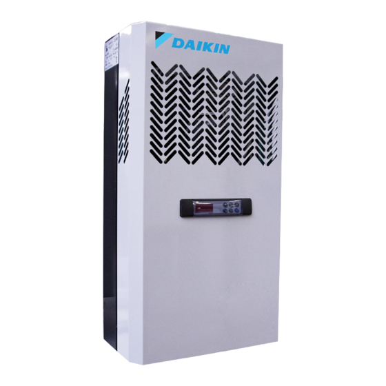
    DESCRIPTION DE LA MACHINE Les unités de la série RCV sont des groupes frigorifiques condensés par air ou par eau (option) construits suivant le principe d’unité monobloc. Ils sont composés de: 1. une unité de condensation installée à l’extérieur de la chambre froide 2.
  • Page 32: Installation De La Machine

    6. INSTALLATION DE LA MACHINE 6.1 Signalisations Le constructeur a prévu l’apposition d’écriteaux d’avertissement et attention avec les signalisations figurant dans le tableau récapitulatif 6.2 Encombrement de la machine LMSW* 030-050 LMSW* 060-075 6.3 Mise en place de la machine Pour obtenir un fonctionnement optimal de l'unité...
  • Page 33: Espaces Libres À Respecter

    6.4 Espaces libres à respecter Dans le but de permettre un usage correct de la machine et un entretien aisé de celle-ci, dans des conditions de sécurité, l’installation doit être effectuée de façon à respecter les espaces libres minimums pour l’ouverture de la machine. 6.5 Montage de la machine A) Faire un trou ayant des dimensions appropriées sur la paroi de la chambre, voir figure.
  • Page 34: Protections Et Précautions De Sécurité

    Protections et précautions de sécurité protections mécaniques Le constructeur a prévu les suivantes: Protections fixes frontales de l’unité d’évaporation et de l’unité de condensation: elles sont fixées à la charpente par des vis de blocage. Protections fixes externes électroventilateurs sur l’unité de condensation et d’évaporation: elles sont fixées par des vis.
  • Page 35: Nettoyage De La Machine

    6.7 Nettoyage de la machine Nettoyer la machine avec soin, en enlevant la poussière et les substances étrangères et les salissures qui se sont éventuellement déposées pendant le déplacement de la machine, avec des détergents ou des dégraissants. ATTENTION Ne pas utiliser de solvants BRANCHEMENT DE LA MACHINE AUX SOURCES D’ENERGIE EXTERNES ATTENTION Avant d’effectuer le branchement électrique, vérifier que le voltage et la...
  • Page 36: Contrôle Du Fonctionnement

    AVERTISSEMENT Pour éviter la sortie de l’eau pendant le remplissage du bac d’humidification, lors du premier démarrage il faut régler au minimum le réducteur de pression et fermer le robinet de l’eau qui se trouve à l’intérieur de l’unité. Contrôle du fonctionnement Lors de la mise en marche de l’unité, il faut contrôler le bon fonctionnement du système d’Humidification Automatique.
  • Page 37: Contrôles Et Réglages À Effectuer

    Sur l’afficheur il y a une série de voyants lumineux, la signification desquels est décrite dans le tableau suivant: LED2 LED3 Display Temper. Display Umidità LED4 Display Température Display Humidité VOYANT MODALITÉ Fonction ALLUME REFROIDISSEMENT RAPIDE activé ALLUME Signalisation ALARME En programmation “Pr2”...
  • Page 38: Schéma Installation Électrique De La Machine

    AVERTISSEMENT Pour permettre à la machine d’augmenter l’humidité ambiante, il faut mettre de l’eau dans le bac situé au-dessous de l’évaporateur (1,5 litres pour LMSW*030-050, 2,5 litres pour LMSW*060-075) - Mettre sous tension le groupe. L’afficheur s’allume et affiche le message OFF - Mettre en marche la machine en appuyant sur la touche ON/OFF Pour afficher et modifier les points de consigne (température et humidite) 1.
  • Page 39: Entretien Extraordinaire

    AVERTISSEMENT Pour éviter des coupures aux mains, utiliser des gants de protection AVERTISSEMENT Avant d’intervenir sur la machine, couper le courant 12.1 Entretien extraordinaire Contrôlez de temps en temps l’état d’usure des contacts électriques et des télérupteurs et éventuellement remplacez-les. 12.2 Interventions devant être effectuées par des professionnels qualifiés ou par le constructeur...
  • Page 40: Alarmes Signalisées Par Le Contrôleur Électronique

    12.5 Alarmes signalisées par le contrôleur électronique Mess. Cause “P1” Sonde thermostat en panne “P3” Sonde humidité en panne “HA” Alarme de haute température “LA” Alarme de basse température “HHA” Alarme de haute humidité “HLA” Alarme de basse humidité “dA” Alarme porte ouverte La signalisation est affichée jusqu’à...
  • Page 41 INHALTSVERZEICHNIS Sicherheits- und sonstige wichtige Hinweise Tabellarischer Überblick zum Typenschild und anderen Schildern Beschreibung der Maschine Funktionsweise der Maschine Transport der Maschine Installation der Maschine Kennzeichnungen Raumbedarf der Maschine Aufstellung der Maschine Wasseranschluss Mindestabstände Montage der Maschine Schutzvorrichtungen und Sicherheitsmaßnahmen Reinigung der Maschine Anschluß...
  • Page 42: Sicherheits- Und Sonstige Wichtige Hinweise

    Ihnen für das Vertrauen, das Sie uns mit der Entscheidung für ein Produkt von Daikin erwiesen haben. Lesen Sie bitte dieses Handbuch aufmerksam durch, das eigens erstellt wurde, um Anleitungen und Hinweise zur fachgerechten Installation sowie zur Bedienung und Wartung des Produkts zu geben und so eine optimale Nutzung aller Funktionen zu ermöglichen.
  • Page 43: Tabellarischer Überblick Zum Typenschild Und Anderen Schildern

    2 TABELLARISCHER ÜBERBLICK ZUM TYPENSCHILD UND ANDEREN SCHILDERN Kältemittel Kondensatablass Achtung: Heiße oder kalte Teile Achtung: Vor Arbeiten an der Maschine Strom abschalten Achtung: Stromschlaggefahr Dieses Kabel mit einem thermo-magnetischen Schalter verbinden, nie mit der Hauptleitung Drehrichtung Farben der Drähte im Stromkabel Achtung –...
  • Page 44: Beschreibung Der Maschine

    3 BESCHREIBUNG DER MASCHINE Bei den Maschinen der Serie LMSW handelt es sich um Kühlgeräte mit Luft- oder (optional) Wasserkondensation, die als Monoblock-Einheiten konstruiert sind und aus folgenden Elementen bestehen: 1. eine Kondensator-Einheit, die außerhalb der Kühlzelle montiert wird, 2. eine isolierende Trennplatte, 3.
  • Page 45: Installation Der Maschine

    6 INSTALLATION DER MASCHINE 6.1 Kennzeichnungen Der Hersteller hat Hinweis- und Warnschilder angebracht, die im „Tabellarischen Überblick zum Typenschild und anderen Schildern“ aufgeführt und beschrieben werden. 6.2 Raumbedarf der Maschine LMSW* 030-050 LMSW* 060-075 6.3 Aufstellung der Maschine Für einen einwandfreien Betrieb der Einheit gelten folgende Empfehlungen: A) Stellen Sie die Maschine in gut belüfteter Umgebung und in Abstand zu Quellen erhöhter Wärmeabstrahlung auf B) Öffnen Sie die Kühlzellentür nur soweit notwendig und nicht zu oft.
  • Page 46 6.4 Mindestabstände Für einen einwandfreien Betrieb und die problemlose Wartung der Maschine muss die Installation in einer Position erfolgen, bei der ein Mindestfreiraum zur Öffnung und Belüftung der Maschine verbleibt. 6.5 Montage A) Erstellen Sie in der Kühlzellenwand eine Öffnung mit den entsprechenden Maßen (siehe Zeichnung).
  • Page 47: Schutzvorrichtungen Und Sicherheitsmaßnahmen

    6.6 Schutzvorrichtungen und Sicherheitsmaßnahmen mechanische Schutzvorrichtungen Der Hersteller hat folgende vorgesehen: Feste Schutzhauben an der Stirnseite der Verdampfungs- und der Kondensatoreinheit; mittels Schrauben am Kälteaggregat befestigt. Mittels Schrauben befestigte Schutzgitter außen an den Elektrogebläsen auf der Kondensator- und auf der Verdampfereinheit. elektrische Schutzvorrichtungen Der Hersteller hat folgende vorgesehen:...
  • Page 48: Reinigung Der Maschine

    6.7 Reinigung der Maschine Die Maschine ist sorgfältig zu reinigen, in dem Staub, Fremdstoffe und andere Verunreinigungen, die sich eventuell während des Transports abgelagert haben, mit Reinigungs- oder Entfettungsmitteln entfernt werden. ACHTUNG Keine Lösungsmittel verwenden 7 ANSCHLUSS DER MASCHINE AN DIE EXTERNE ENERGIEVERSORGUNG ACHTUNG Vor dem Anschluss an das Stromnetz sicherstellen, dass Spannung und Frequenz des Versorgungsnetzes mit den Angaben auf dem Typenschild der...
  • Page 49: Anschluss An Feuchtgkeit Anlage

    Anschluss an feuchtgkeit Anlage Schließen Sie die Leitung (5) des Befeuchters an: Das für den Anschluss verwendete Rohr muss einen Durchmesser von zumindest 10 mm aufweisen, der Druck der Wasserleitung muss zwischen 1,5 atm und 3 atm betragen. Vor dem Wassereinlauf ist zudem ein Reduzierventil und ein Filter zu installieren. HINWEIS Um während dem Auffüllen der Befeuchtungsschale zu vermeiden, dass Wasser herausläuft, das Reduzierventil bei der ersten Inbetriebnahme auf den...
  • Page 50 set point Zur Anzeige oder Veränderung des für die Feuchtigkeit. Bei der Programmierung wird damit ein Parameter gewählt oder ein Wert bestätigt. Bei der Programmierung werden damit die Parameter durchlaufen oder ihr Wert erhöht. Bei der Programmierung werden damit die Parameter durchlaufen oder ihr Wert vermindert.
  • Page 51: Durchzuführende Kontrollen, Regulierungen Und Einstellungen

    DURCHZUFÜHRENDE KONTROLLEN, REGULIERUNGEN UND EINSTELLUNGEN Vor dem Einschalten der Maschine ist sicherzustellen, dass die Befestigungsschrauben angezogen sind, – die elektrischen Anschlüsse sachgemäß eingerichtet worden sind. – Wasser Zu- und Abfluss sichergestellt sind. – Falls die Einheit geöffnet werden muss, ist darauf zu achten, dass kein Werkzeug im Innern der Maschine zurückbleibt, –...
  • Page 52: Schaltplan Der Maschine

    10 CHALTPLAN DER MASCHINE Die Maschinen der Serie LMSW sind mit einer elektrischen Anlage ausgestattet, deren Schaltplan dem vorliegenden Gebrauchs- und Wartungshandbuch beigefügt ist. 11 WARTUNG UND REPARATUR Die sachgemäße Wartung ist ein entscheidender Faktor für die lange Lebensdauer der Maschine unter optimalen Betriebs- und Leistungsbedingungen und für die Gewährleistung der Sicherheitsvorkehrungen, die vom Hersteller eingerichtet wurden.
  • Page 53: Unzureichende Leistung Der Maschine

    Bei Fehlfunktion der Wasserversorgung ist der Wasserzulauf abzusperren und der Fehler zu suchen. Mögliche Ursachen können sein, Zulaufventil verschmutzt oder verklemmt; Fehler in der Regelung des Zulaufventils. Zur Notversorgung kann Wasser mittels Gießkanne an geeigneter Stelle in den Verdampferluftauslass (unten) nachgefüllt werden. 12.4 Unzureichende Leistung der Maschine Ist die Leistung der Maschine unzureichend und ergibt eine Überprüfung technischer Ursachen, dass in der...
  • Page 54: Entsorgung Der Maschine

    15 ENTSORGUNG DER MASCHINE Bei Verschrottung müssen die Bestandteile der Maschine entsprechend den jeweils geltenden Gesetzen des Landes, in dem die Maschine eingesetzt wurde, von Firmen entsorgt werden, die zum Sammeln und Recyceln von Sonderabfällen befugt sind. HINWEIS Die Kühlflüssigkeit darf nicht in die Atmosphäre gelangen und muss von Firmen, die zum Sammeln von Sonderabfällen befugt sind, recycelt und entsorgt werden.
  • Page 55 INHOU Veiligheidsaanbevelingen Tabel met waarschuwings- en aandachtsplaten Beschrijving van de unit Werking Verplaatsen Montage Platen Afmetingen Locatie Vrije ruimte Montage Het afstandsbedieningspaneel plaatsen Veiligheidsvoorzieningen Reiniging De unit aansluiten Elektrische aansluiting Aansluiting op het watersysteem Aansluiting op het bevochtigingssysteem Elektrische bediening Bedieningspaneel Controles, regels en aanpassingen Starten...
  • Page 56 Daikin hebt gekozen. Lees deze instructies zorgvuldig door. Ze bevatten details en advies over de juiste montagemethode, het gebruik en het onderhoud om zo een maximaal betrouwbare, efficiënte en duurzame unit te krijgen. 1 VEILIGHEIDSAANBEVELINGEN Volg tijdens de montage en het gebruik van de unit onderstaande aanbevelingen.
  • Page 57: Tabel Met Waarschuwings- En Aandachtsplaten

    2 TABEL MET WAARSCHUWINGS- EN AANDACHTSPLATEN Koelmiddel Condensafvoerleiding Opgelet: warme of koude onderdelen Opgelet: Schakel de unit uit alvorens eraan te werken. Opgelet: gevaar voor elektrocutie Sluit deze kabel op een stroomonderbreker aan, op de hoofdleiding Draairichting Kleuren van voedingskabels Opgelet –...
  • Page 58: Beschrijving Van De Unit

    BESCHRIJVING VAN DE UNIT De reeks LMSW bestaat uit luchtgekoelde of watergekoelde (optioneel) units op basis van het principe met enkelvoudige blokken. Deze bestaan uit: 1. een condensatie-unit buiten de koelruimte; 2. een geïsoleerde panel 3. een verdamper in de koelruimte 4.
  • Page 59: Montage

    MONTAGE a. Platen Er staan waarschuwings- en aandachtsplaten op de unit, zoals opgelijst in de relevante tabel. Afmetingen LMSW* 030 - 050 LMSW* 060 - 075 Locatie Voer de volgende handelingen uit voor een optimale werking van de unit: Plaats de unit in een goed geventileerde ruimte, ver van warmtebronnen. Beperk het aantal keren dat de deur wordt geopend.
  • Page 60 6.5 Installation A) Maak een opening met geschikte afmetingen in de muur van de koelruimte (zie afbeelding). B) Plaats de unit op de muur van de koelruimte door het verdampergedeelte in de opening te steken. C) Zet de unit met de meegeleverde schroeven vast. Injecteer silicone helemaal rond de opening van het paneel om deze luchtdicht te maken...
  • Page 61: De Unit Aansluiten

    6.6 Veiligheidsvoorzieningen mechanische veiligheidsvoorzieningen De unit beschikt over de volgende Vaste bescherming aan de bovenkant en de zijkant voor verdamper en condensatie-unit, vastgezet met borgschroeven. Externe ventilatorbeschermingen op de verdamper- en condensatie-units, vastgezet met schroeven. elektrische veiligheidsvoorzieningen De unit beschikt over de volgende Bescherming van ventilatoren (van motoren) tegen hoge vermogensabsorptie;...
  • Page 62 Elektrische aansluiting Controleer de paneelonderdelen alvorens de unit aan te sluiten. OPGELET Voor de aansluiting op het elektrische net kiest de installateur een geschikte veiligheidsvoorziening (een stroomonderbreker of een differentieelschakelaar) op basis van de betrokken leiding en van de absorptie die op de plaat van de unit staat. Als er meerdere units in een koelruimte staan, dan moet elke unit een eigen veiligheidsvoorziening hebben.
  • Page 63: Elektrische Bediening

    a) een verbrande bevochtigingsverwarming, b) storing van de bevochtigingsthermostaat met daardoor een ongecontroleerd waterpeil in de bak. Als er kalkaanslag is, reinig dan de betrokken onderdelen met speciale producten om kalkaanslag te verwijderen. WAARSCHUWING Elke reiniging mag alleen uitgevoerd w orden w anneer de unit uitgeschakeld is. 8 ELEKTRISCHE BEDIENING 8.1 Bedieningspaneel Om de ingestelde doeltemperatuur weer te geven en te...
  • Page 64: Controles, Regels En Aanpassingen

    KNIPPERT Programmeerfase instelling vochtigheidsgraad (umid) CONTROLES, REGELS EN AANPASSINGEN Controleer het volgende alvorens de unit in te schakelen: - De borgschroeven zitten goed vast. - De elektrische aansluitingen zijn correct aangesloten. Als de unit geopend is: - Er ligt geen gereedschap meer in. - De montage is juist gebeurd.
  • Page 65: Routinematig Onderhoud

    Goed onderhoud is essentieel voor een langere levensduur, perfecte werkomstandigheden en een hoog rendement van de unit, maar ook voor de veiligheidsvoorzieningen van de fabrikant. ROUTINEMATIG ONDERHOUD Voor een goede werking van de unit moet de condensor regelmatig gereinigd worden (de frequentie is afhankelijk van de omgeving waar de unit is geplaatst).
  • Page 66: Reserveonderdelen Bestellen

    Het is absoluut verboden om beschermingsmiddelen te verwijderen terw ijl de machine in werking is. Deze zijn er om de veiligheid van de gebruiker te verzekeren. 12.5 Alarmen Bericht Oorzaak “P1” Storing thermostaatsonde “P3” Storing vochtsonde “HA” Alarm hoge temperatuur “LA”...
  • Page 68   0MAN311   2017.08...

Ce manuel est également adapté pour:

LbbwhLbwwhLbcwh

Table des Matières