Télécharger Imprimer la page

Publicité

Les langues disponibles

Les langues disponibles

Liens rapides

Deutsch
English
Français
Latest Product Information: www.knick.de
User Manual
P 15000
Normsignal-Trennverstärker
3
Isolated Standard Signal Conditioners
13
Amplificateurs séparateurs
25
de signaux normalisés

Publicité

loading

Sommaire des Matières pour Knick P 15000

  • Page 1 User Manual P 15000 Normsignal-Trennverstärker Deutsch Isolated Standard Signal Conditioners English Amplificateurs séparateurs Français de signaux normalisés Latest Product Information: www.knick.de...
  • Page 2 Beim Umgang mit den Bausteinen ist auf Schutzmaßnahmen gegen elektrostatische Entladung (ESD) zu achten. Vorsicht! Die Normsignal-Trennverstärker der Reihe VariTrans® P 15000 dürfen nur durch vom Betreiber autorisiertes, qualifiziertes Fachpersonal installiert werden. Erst nach der fachgerechten Installation darf das Gerät mit Hilfsenergie versorgt werden.
  • Page 3 Bestimmungsgemäßer Gebrauch Die Normsignal-Trennverstärker der Reihe P 15000 dienen zur galvani- schen Trennung von Normsignalen 0(4) ... 20 mA und 0 ... 10 V. Ein- und Ausgangssignal sind je nach Typ fest eingestellt oder über DIP-Schalter kalibriert umschaltbar. Ein Nachjustieren der umschaltbaren Typen ist nicht erforderlich.
  • Page 4 3.3 Einstellungen Einstellung des Ein- und Ausgangs- bereiches mittels der DIP-Schalter S1 und S2 gemäß Tabelle. Eingang Ausgang 0 ... 20 mA 0 ... 20 mA 0 ... 20 mA 4 ... 20 mA 0 ... 20 mA 0 ... 10 V 4 ...
  • Page 5 Montage Die Normsignal-Trennverstärker werden auf TS 35 Normschienen aufgerastet. Der elektrische Anschluss Klemmenbelegung 1 Eingang + Strom 2 Eingang – Strom 3 Eingang + Spannung 4 Eingang – Spannung 5 Ausgang + 6 Ausgang – 7 Hilfsenergie 8 Hilfsenergie Anschlussquerschnitt max. 2,5 mm Mehrleiteranschluss max.
  • Page 6 Abmessungen • Bauform F1: mit festen Schraubklemmen Metallschloss zur Befestigung Schraubklemmen auf der Hutschiene • Bauform H1: mit steckbaren Schraubklemmen...
  • Page 7 Erklärungen, Genehmigungen und Zulassungen Konformitätserklärung zur Niederspannungs- und EMV-Richtlinie unter www.knick.de UL Listed, File No. E340287, Standard: UL 61010-1, CAN/CSA C22.2 No. 61010-1 Certificate No. 14593-99HH Environmental Category: D Test Standard: Regulations of the Performance of Type Tests, Part 1...
  • Page 8 Bestelldaten Geräte umschaltbar Bestell-Nr. mit steckbarer mit fester Schraubklemme Schraubklemme Normsignal-Trennverstärker P 15000 P 15000 H1 P 15000 F1 Eingang und Ausgang kalibriert umschaltbar Geräte fest eingestellt Bestell-Nr. Eingang Ausgang mit steckbarer mit fester Schraubklemme Schraubklemme 0 ... 20 mA 0 ...
  • Page 9 Ausgangsspannung ≤ 10 mA (1 kΩ bei 10 V) Offset 20 µA bzw. 10 mV Restwelligkeit < 10 mV Allgemeine Daten Verstärkungsfehler < 0,08 % v.M. Temperaturkoeffizient < 50 ppm/K v.E. Grenzfrequenz > 10 kHz; P 15000 F1/H1 auf < 10 Hz umschaltbar...
  • Page 10 Prüfspannung 4 kV AC Eingang gegen Ausgang gegen Hilfsenergie 1000 V AC/DC bei Überspannungskategorie II und Arbeitsspannung Verschmutzungsgrad 2 nach DIN EN 61010-1 (Basisisolierung) Bei Anwendungen mit hohen Arbeitsspannungen ist auf genügend Abstand bzw. Isolation zu Nebengeräten und auf Berührungsschutz zu achten. Schutz gegen gefährliche Sichere Trennung nach DIN EN 61140 (VDE 0140 Teil 1) Körperströme...
  • Page 11 Schutzart IP 20 ca. 150 g Gewicht Höhere Belastung des Spannungsausgangs auf Anfrage Mittlerer Tk im spezifizierten Betriebs-Temperaturbereich -10 °C ... +70 °C. UL: Arbeitsspannung (Basisisolierung) bis zu 600 V bei Überspannungskategorie II und Verschmutzungsgrad 2 Während der Störeinwirkung sind geringe Abweichungen möglich.
  • Page 13 P 15000 Isolated Standard Signal Conditioners English Latest Product Information: www.knick.de...
  • Page 14 (ESD) when handling the devices! CAUTION! The VariTrans® P 15000 isolated standard signal conditioners shall only be installed by qualified and specially trained personnel authorized by the operating company. Do not connect the device to power supply before it is professionally installed.
  • Page 15 Intended Use The Series P 15000 isolated standard signal conditionersare used for galvanic isolation of 0(4) to 20 mA and 0 to 10 V standard signals. Depending on the model, input and output signal ranges are permanently set or you can select calibrated ranges by means of DIP switches.
  • Page 16 3.3 Settings Set the input / output range using DIP switches S1 and S2 as indicated in the table. Input Output 0 to 20 mA 0 to 20 mA 0 to 20 mA 4 to 20 mA 0 to 20 mA 0 to 10 V 4 to 20 mA 0 to 20 mA...
  • Page 17 Mounting The isolated standard signal conditioners are mounted on standard TS 35 rails. Electrical Connection Terminal Assignments 1 Input + current 2 Input – current 3 Input + voltage 4 Input – voltage 5 Output + 6 Output – 7 Power supply 8 Power supply Conductor cross-section max.
  • Page 18 Dimensions • Type F1: with fixed screw terminals Metal interlock to attach Screw terminals to top hat rail • Type H1: with pluggable screw terminals All dimensions in mm...
  • Page 19 Declarations, Certificates and Approvals See www.knick-international.com for Declaration of Conformity with Low Voltage and EMC Directive. UL Listed, File No. E340287, Standard: UL 61010-1, CAN/CSA C22.2 No. 61010-1 Certificate No. 14593-99HH Environmental Category: D Test Standard: Regulations of the Performance of Type Tests, Part 1...
  • Page 20 Order Information Models with switch selection Ref. No. With pluggable With fixed screw terminals screw terminals P 15000 Isolated Standard Signal Conditioners P 15000 H1/ P 15000 F1 Input and output adjustable to calibrated ranges Models with fixed settings Ref. No.
  • Page 21 With output voltage ≤10 mA (1 kΩ at 10 V) Offset 20 µA or 10 mV Residual ripple < 10 mV General data Gain error < 0.08 % meas.val. Temperature coefficient < 50 ppm/K full scale Cutoff frequency > 10 kHz, P 15000 F1/H1 switchable to < 10 Hz...
  • Page 22 Test voltage 4 kV AC input against output against power supply 1000 V AC/DC with overvoltage category II and pollution Working voltage degree 2 according to EN 61010-1 (basic insulation) For applications with high working voltages, take measures to prevent accidental contact and make sure that there is sufficient distance or insulation between adjacent devices.
  • Page 23 Ingress protection IP 20 Approx. 150 g Weight Higher load on the voltage output on request Average TC in specified operating temperature range -10 °C to +70 °C UL: working voltage (basic insulation) up to 600 V for overvoltage category II and pollution degree 2 Slight deviations are possible while there is interference.
  • Page 25 P 15000 Amplificateurs séparateurs Français de signaux normalisés Latest Product Information: www.knick.de...
  • Page 26 Consignes de sécurité Le symbole d’avertissement sur l’appareil (point d’exclamation dans un triangle) signifie : lisez ce manuel utilisateur, observez les caractéristiques techniques et respectez les consignes de sécurité ! Avertissement ! Protection contre les chocs électriques Dans le cas d’applications avec des tensions de service élevées, observer une distance suffisante ou assurer une isolation avec les appareils voisins et veiller à...
  • Page 27 
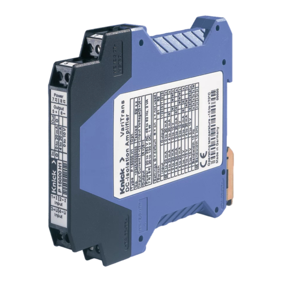
L’exploitant de l’installation est responsable de la sécurité de l’installation dans laquelle l’appareil est utilisé. Configuration (seulement P 15000 F1 et P 15000 H1) 3.1 Outillage Pour ouvrir l’appareil et raccorder les conducteurs aux bornes à vis il faut avoir un tournevis avec une étendue de 3 mm.
  • Page 28 3.3 Réglages Réglage des plages d’entrée et de sortie selon tableau en utilisant les switches DIP S1 et S2. Entrée Sortie 0 ... 20 mA 0 ... 20 mA 0 ... 20 mA 4 ... 20 mA 0 ... 20 mA 0 ...
  • Page 29 Montage Les amplificateurs séparateurs de signaux normalisés sont encliquetés sur des rails normalisés TS 35. Le raccordement électrique Affectation des bornes 1 Entrée + courant 2 Entrée – courant 3 Entrée + tension 4 Entrée – tension 5 Sortie + 6 Sortie –...
  • Page 30 Dimensions • Type F1 avec bornes à vis fixes Verrou métallique pour fixation Bornes à vis sur le rail DIN • Type H1 avec bornes à vis enfichables...
  • Page 31 Déclarations, certificats et homologations Vous trouverez la déclaration de conformité aux directives basse tension et CEM sur notre site : www.knick-international.com UL Listed, File No. E340287, Standard: UL 61010-1, CAN/CSA C22.2 No. 61010-1 Certificate No. 14593-99HH Environmental Category: D Test Standard: Regulations of the Performance of Type Tests, Part 1...
  • Page 32 Appareils avec plages commutables Référence avec bornes à vis avec bornes à vis enfichables fixes Amplificateur séparateur de signaux P 15000 H1 P 15000 F1 normalisés P 15000 Entrée et sortie calibrées commutables Appareils à réglages fixes Référence Entrée Sortie avec bornes à...
  • Page 33 20 µA ou 10 mV Ondulation résiduelle < 10 mV Caractéristiques générales Erreur de gain < 0,08 % de val. mes. Coefficient de température < 50 ppm/K d. f. Fréquence limite > 10 kHz; P 15000 F1/H1 commutable à < 10 Hz...
  • Page 34 Tension d’essai 4 kV CA entre entrée et sortie et alimentation 1000 V CA/CC pour la catégorie de surtensions II et le degré Tension de service de pollution 2 selon EN 61010-1. (isolation principale) Dans le cas d’applications avec des tensions de service élevées, observer une distance suffisante ou assurer une isolation avec les appareils voisins et veiller à...
  • Page 35 Protection IP 20 Env. 150 g Poids Charge plus élevée pour la sortie tension sur demande CT moyen dans la plage de températures spécifiée -10 °C ... +70 °C UL: tension de service (isolation principale) jusqu‘à 600 V pour catégorie de surtension II et degrée de pollution 2 De faibles différences sont possibles pendant les interférences.
  • Page 36 Knick Elektronische Messgeräte GmbH & Co. KG Beuckestraße 22 14163 Berlin Germany Phone: +49 30 80191-0 Fax: +49 30 80191-200 Email: knick@knick.de Web: www.knick.de 090299 TA-250.100-KNX03 20151202...