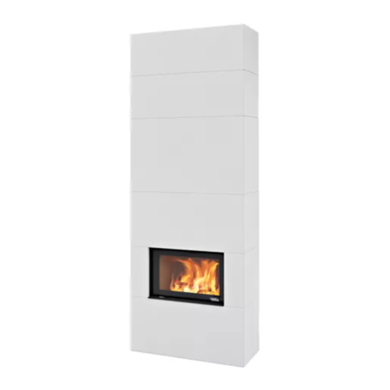
Nordpeis Panama EU Manuel D'installation
Masquer les pouces
Voir aussi pour Panama EU:
- Manuel d'installation (52 pages) ,
- Manuel d'installation (52 pages)

Manuels Connexes pour Nordpeis Panama EU


Sommaire des Matières pour Nordpeis Panama EU
- Page 1 Installation manual Montageanleitung Manuel d’installation Manuale d’installazione Panama EU Art.no: FP-PAN01-000 Last updated: 25.06.2014 Test Report No: 40 14 3609 / 40 14 3610...
- Page 2 All safety distances are minimum distances. Installation of the insert must comply with the rules and Floor plate regulations of the country where installed. Nordpeis AS A fireproof floor plate must be put in front of the fireplace is not responsible for wrongly assembled inserts.
- Page 3 Panama EU - Straight / Corner Attention! The airflow behind Panama is a Insert prerequisite for cooling down a combustible wall. Q-34AL (R/L) / Q-23 FL The air gap must not under any circumstances be covered as this may cause a fire.
- Page 4 Sie die Oberfläche mit einem Aufbau – und Bedienungsanleitung ist zu beachten. feuchten Schwamm. So entfernen Sie den Staub und Nordpeis / Northstar haftet nicht für unsachgemäße sorgen für eine bessere Haftung. Um ein gutes Installation oder unsachgemäßen Betrieb.
- Page 5 Luftmenge ausreichend ist. Hierauf ist besonders bei baurechtlichen Vorschriften. dichtschließenden Fenstern und Türen (Dichtlippe) zu achten. Nordpeis AS / Northstar übernehmen für falsch montierte oder verändert montierte Kaminanlagen keine Verantwortung, Die Schornsteinberechnung erfolgt nach DIN EN Haftung und / oder Gewährleistung.
- Page 6 Betriebsdauer beendet ist. ist DIN EN 13384-1 bzw. DIN EN 13384-2 anzuwenden. Während des Anheizens sollte der Aufstellraum gut Der Raumheizer Panama EU ist eine belüftet werden. Ein schnelles Durchlaufen Zeitbrand-Feuerstätte. der Anheizphase ist wichtig, da bei Bedienungsfehlern höhere Emissionswerte auftreten können.
- Page 7 Panama EU Holzfach 220 kg Panama EU Holzfach H Sicherheitsabstand zu brennbarem Material (FIG 2) Vergewissern Sie sich, dass alle Sicherheitsabstände eingehalten werden. Mindestgröße der Hitzeschutzwand Panama EU verfügt über eine integrierte Hitzeschutzwand und kann direkt vor eine brennbare Wand montiert werden...
- Page 8 Lorsque le foyer est assemblé, uti- défectueux d’un insert ou d’un poêle. lisez la même colle acrylique pour remplir les joints (Fig. Nordpeis se réserve le droit de modifier, à tout moment et sans préavis, les caractéristiques techniques et Dommages mineurs dimensionnelles deses produits.
- Page 9 Taille minimale de mur pare-feu Panama EU a un pare-feu intégré et peut être monté directement contre un mur combustible Si le conduit passe un mur inflammable, respecter le DTU 24-2.
- Page 10 è importante che le due strutture del rivestimento e dell’inserto siano fra loro indipendenti. (Sopra l’inserto Nordpeis AS non è responsabile per inserti non corretta- ci deve essere uno spazio di 3 a 5 mm. Lateralmente mente assemblati.
- Page 11 264 kg Panama EU con protezione posteriore 70 kg Panama EU solo elemento aggiuntivo 140 kg Panama EU set panca frontale e lato 200 kg Panama EU porta legna verticale 220 kg Panama EU porta legna verticale alto Pedana salva pavimento Seguire i regolamenti locali in materia di protezione del pavimento combustibile.
- Page 12 You need the following tools DE Folgende Werkzeuge sind notwendig. Vous avez besoin des outils suivants Attrezzi ed utensili necessari 2.5 mm 10 mm 3 mm 13 mm 4 mm 5 mm 24 mm...
- Page 13 FIG 1A Panama EU Straight High / Q23FL =mm Panama EU Straight Standard / Q-23FL=mm...
- Page 14 Panama EU Corner Right High / Q-34AL/R =mm Panama EU Corner Right Standard / Q-34AL/R =mm...
- Page 15 FIG 1B Chimney connection - Panama EU Standard Straight / Q-23FL = mm Chimney connection - Panama EU Standard Corner / Q-34AL L/R =mm...
- Page 16 Panama EU =mm AIR SECTION A-A...
- Page 17 =Firewall/ Hitzenschutzwand / Mur parfeu / Parete non combustibile =Combustible material / Brennbarem Material / Matières combustibles/ Parete combustibile Panama EU Straight with Q-23FL 150 mm 500 mm Panama EU Corner with Q-34AL ( right / rechts) 0 mm Panama EU Corner with Q-34AL (left / links)
- Page 18 Attention ! Si le produit doit être raccordé à une amenée d’air frais séparée, veillez à préparer le socle avant de le mettre en place. Voir FIG Panama EU AIR pour les mesures. Posizionare la base (A). Assicurarsi che sia a livello. Se il caminetto viene posizionato vicino ad un angolo, rispettare la distanza di +/-170 mm dalla parete (B).
- Page 19 Panama EU Standard / High - Q-23FL FIG 4 42mm ̴ ̴ ̴ 13 mm 1. Place insert on the bottom plate in initial position according to dimensions on the drawing. 2. Regulate the height of the legs to approximate dimension according the drawing.
- Page 20 Panama EU Standard / High - Q-34 AL - left version FIG 4a ̴ ̴ ̴ 13 mm 1. Place insert on the bottom plate in initial position according to dimensions on the drawing. 2. Regulate the height of the legs to approximate dimension according the drawing.
- Page 21 Panama EU Standard / High - Q-23FL / Q-34AL FIG 5 FIG 5b 21-30006-008 x2 21-50005-040 x2...
- Page 22 Panama EU Standard / High - Q-23FL / Q-34AL FIG 6 21-30006-008 x2 21-50005-040 x2 FIG 6b CO-PAN01-110...
- Page 23 Attention ! Si le produit doit être raccordé à une amenée d’air frais séparée, veillez à préparer la plaque pare-feu avant de la mettre en place. Voir FIG Panama EU AIR pour les mesures. Posizionate la piastra di protezione posteriore.
- Page 24 Panama EU Standard - Q-23FL FIG 8 5 mm 1. Take side parts and place as shown on the drawing in order to check proper position of the Insert relating to the parts. 2. If position of the Insert is incorrect set final position.
- Page 25 Panama EU Standard - Q-34AL FIG 8b 5 mm 1. Take side parts and place as shown on the drawing in order to check proper position of the Insert relating to the parts. 2. If position of the Insert is incorrect set final position.
- Page 26 FIG 9 Panama EU Standard - Q-23FL / Q-34AL Place concrete part on the place. Positionieren Sie das Verkleidungsteil wie gezeigt. Placez l’élément en béton en place. Posizionate la parte superiore in cemento facendola scendere dall’alto.
- Page 27 Posizionate la piastra superiore di protezione posteriore come indicato nel disegno. Attenzione! Se il caminetto deve essere collegato alla canna fumaria nella parte posteriore es- eguire prima il foro sulla piastra. Vedi Fig. 1B Uscita Fumi PANAMA EU per le misure.
- Page 28 FIG 11 In case of back chmney connection setting going through combustiible wall, by means of uninsulated conector, use the concrete ring to protect combustible wall against contact with uninsulated conector pipe. Wird die Kaminanlage nach hinten angeschlossen, verwenden Sie den beiliegenden Ring wie gezeigt. Si le raccord de cheminée arrière passe à...
- Page 29 Panama EU Standard / High - Q-23FL / Q-34AL FIG 12 Place concrete part as it shown on the drawing Positionieren Sie das Verkleidungselement wie in der Zeichnung dargestellt. Placez l’élément en béton en place comme est indiqué sur le plan.
- Page 30 Panama EU Standard / High - Q-23FL / Q-34AL FIG 12b FIG 12c ◦...
- Page 31 Panama EU Standard / High - Q-23FL FIG 13 90 ⁰ 22-PAN01-120 x1 21-40000-065 x2 22-PAN01-150 x3 21-40000-065 x3 22-PAN01-140 x1 90 ⁰ 22-PAN01-130 x1...
- Page 32 Panama EU Standard / High - Q-23FL FIG 14 90 ⁰ 22-PAN01-150 x3 22-PAN01-120 x1 90 ⁰ x5 22-PAN01-150 x1 21-40000-065 x2 22-PAN01-130 x1 21-40000-065 x6 22-PAN01-140 x1...
- Page 33 Panama EU Standard / High - Q-23FL / Q-34AL FIG 15 1. Place the heat shield cover into surrounding FIG 15A 2. One of the ends of the cover must be placed on the insert shield cover, FIG 15B. 1. Setzen Sie die Hitzeschutzabdeckung in die Einfassung ein Abb. 15A 2.
- Page 34 Posizionate le due parti del coperchio nell’ordine prima la parte 1 e poi la parte 2. Attenzione! Se il caminetto deve essere collegato alla canna fumaria nella parte superiore es- eguire prima i fori su entrambe le parti del coperchio. Vedi Fig. 1B Uscita Fumi PANAMA EU per le misure.
- Page 35 Panama EU High - Extension Q-23FL / Q-34AL FIG 17 Place concrete part on its place. Bringen Sie das Verkleidungselement an. Placez l’élément en béton en place. Posizionate l’elemento di sopralzo come indicato nel disegno.
- Page 36 Panama EU High - Extension - Q-23FL / Q-34AL FIG 18 Place concrete parts on its place. Attention: To assemble the part a stable platrorm could be needed to place the part on its place. Bringen Sie die Verkleidungselemente an.
- Page 37 Panama EU Standard / High - Q-23FL / Q-34AL FIG 19 90⁰ 1. Place a grate frame initially in a concrete window. 2. Push it inside to the limit. 3. Draw a line on the frame surface of assembling plate marking the edge of inside window wall. See detailed FIG19B. 4. Repeat action for each as- sembling plate.
- Page 38 Panama Standard / High - Q-23FL / Q-34AL FIG 20 1. Place air grates on its place. 2. Apply acril glue on joining surfaces 1. Montieren Sie das Lüftungsgitter. 2. Verwenden Sie das Acryl zum Verkleben der Verkleidungselemente. 1. Posizionate le griglie nelle varie sedi. 2.
- Page 40 Nordpeis AS, Gjellebekkstubben 11, N-3420 LIERSKOGEN, Norway www.nordpeis.no...