Télécharger Imprimer la page

Publicité

Les langues disponibles

Les langues disponibles

Liens rapides

OWNER'S MANUAL
BEDIENUNGSANLEITUNG
MODE D'EMPLOI
RCM-26
Remote Control Module

Publicité

Chapitres

loading

Sommaire des Matières pour Electro-Voice IRIS Net RCM-26

  • Page 1 OWNER’S MANUAL BEDIENUNGSANLEITUNG MODE D’EMPLOI RCM-26 Remote Control Module...
  • Page 2: Table Des Matières

    CONTENTS Introduction ..........6 System Description .
  • Page 3 MATIÈRES Introduction ..........49 Description du système .
  • Page 4 IMPORTANT SAFETY INSTRUCTIONS The lightning flash with arrowhead symbol, within an equilateral tri- angle is intended to alert the user to the presence of uninsulated “dangerous voltage“ within the product’s enclosure that may be of sufficent magnitude to constitute a risk of electric shock to persons. The exclamation point within an equilateral triangle is intended to alert the user to the presence of important operating and mainte- nance (servicing) instructions in the literature accompanying the...
  • Page 5 IMPORTANT SERVICE INSTRUCTIONS CAUTION: These servicing instructions are for use by qualified personnel only. To reduce the risk of electric shock, do not perform any servicing other than that contained in the Operating Instructions unless you are qualified to do so. Refer all servicing to qualified service personnel.
  • Page 6: Introduction

    The RCM-26 Remote Control Module is a two-channel digital controller module for live sound reinforcement, PA and fixed installation applications. The module can be used in a variety of Electro-Voice® and Dynacord® amps. Installing the RCM-26 turns a conventional amp into a remote amplifier, which, at any time, provides complete overview of the overall system status and control of all system parameters.
  • Page 7: Unpacking And Warranty

    all settings (filters, delay, level, etc.) stay intact, independent of the control by the network. Furthermore, the RCM-26 provides a control port with freely programmable control inputs and control outputs. Control inputs (GPI's) allow the connection of switches. IRIS-Net™ offers the possibility to program a variety of logic functions for the inputs (e.g.
  • Page 8: Installation Notes

    1.3 Installation Notes Installation 1. Switch the power amp’s power off and pull the mains plug 2. Remove the cover panel from the rear panel (4 screws) 3. Insert the RCM-26 module in the slot and lock it in place on the rear panel using the 4 screws (see illustration 1.1) Illustration 1.1: Installation of a RCM-26 4.
  • Page 9: Iris-Net

    The conversion is done by changing the jumper settings of jumper JP1 to JP5 on the RCM-26. The following pictures show the jumper settings for "Pre Fader" mode and "Post Fader" mode. Only the jumper settings shown are allowed. Illustration 1.2: Pre Fader mode (left) and Post Fader mode (right) Note: On RCM-26 Remote Control Modules built in 2006 there are no jumpers at JP1 to JP5, instead the conversion has to be done via „cut&solder“.
  • Page 10 The following illustrations show an example of a power amplifier system in IRIS- Net™ and the DSP flow chart of a RCM-26 Illustration 1.3: Power amplifier system with User Controls Illustration 1.4: DSP flow diagram of the RCM-26 RCM-26 Remote Control Module Owner’s Manual...
  • Page 11: Controls And Connections

    2 Controls and Connections 1, AES/EBU-IN A digital AES/EBU input (AES3) is provided in addition to internal analog inputs. The digital input signal has to be connected to the AES/EBU IN connector. The AES/EBU input is a balanced transformer-isolated input. A sampling rate converter translates the input signal to match the internal sampling rate.
  • Page 12: 2, Aes/Ebu-Out

    2, AES/EBU-OUT The AES/EBU OUT connector allows looping-through the digital audio signal to other RCM-26 modules. The digital input signal gets internally buffered and preprocessed (level matching / slew rate) before it is output via the OUT- connector. This allows fairly simple wiring between modules, without the need for AES/EBU distribution amps as they are usually used.
  • Page 13 monitoring of input or output signals of all power amps in the remote network, without the need for additional wiring. Nominal output level is +6 dBu (1.55 V) and maximum output level is +21 dBu (8.7 V). The CAN bus allows using different data rates, whereas the data rate is inversely proportional to the bus length.
  • Page 14: 5, Status Led

    Colour Name T568A T568B CAN_GND Green Orange CAN_H (+) Blue CAN_L (-) Blue striped MONITOR BUS + Brown striped MONITOR BUS - Brown Table 2.2: Overview CAN plug 5, STATUS LED The STATUS-LED is for monitoring the communication on the CAN bus.
  • Page 15 HIGH Address Stand-alone 1...F 1...15 0...F 16...31 0...F 32...47 0...F 48...63 0...F 64...79 0...F 80...95 0...F 96...111 0...F 112...127 0...F 128...143 0...F 144...159 0...F 160...175 0...F 176...191 0...F 192...207 0...F 208...223 0...F 224...239 0...A 240...250 B...F reserved Tabelle 2.3: CAN addresses Address 0 (00 hex, delivery status) disables remote communication between the RCM-26 and the bus.
  • Page 16: 7, Control Port

    7, CONTROL PORT The CONTROL PORT of the RCM-26 provides two control inputs, two control outputs and reference connections for +5V and ground. The control inputs are configurable via IRIS-Net™. They can be used for example for switching between power on / standby modes, switching between presets or to control parameters.
  • Page 17 The following table shows the factory-fixed settings of the RCM-26’s RS-232 interface. The connected device (e.g. a PC with terminal program, multi-media control software) needs to be identically configured for data transfer to work properly. Parameter Value Data bit Parity bit Stop bit Transfer rate 19200 bit/s...
  • Page 18: Can Bus Principles

    3 CAN Bus Principles The network topology used by the CAN bus is based on the so-called “bus or line topology”, i.e. all participants are connected via a single two-wire cable (Twisted-Pair cable, shielded or unshielded) with the cabling running from one participant on the bus to the next, allowing unlimited communication among all devices.
  • Page 19: System Examples

    can be increased up to 250 by connecting several CAN bus systems. This limitation of exactly 250 devices results from the addressing scheme used by the CAN bus. The addressing scheme allows the allocation of a maxi- mum of 250 different CAN device addresses. •...
  • Page 20: Performance Specifications

    Illustration 3.3: System with 2 amp-racks and 1 USB-CAN-Converter. Terminati- on plugs at amp 6 (first unit on the bus) and amp 12 (last unit on the bus) 3.2 Performance Specifications According to the ISO 11898-2 standard, CAN-bus data transfer cabling has to be carried out using Twisted-Pair cables with or without shielding providing a characteristic impedance of 120 Ω.
  • Page 21 Data Transmission Cable Resistance Bus Length Termination Max. Data per Unit (in Ω) (in m) Transfer Rate Cable Diameter Length (in mΩ/m) 0,25...0,34 mm² 1000 kbit/s 0...40 < 70 AWG23, AWG22 at 40 m 0,34...0,6 mm² 500 kbit/s 40...300 < 60 AWG22, AWG20 at 100 m 0,5...0,6 mm²...
  • Page 22 General Note: • As long as only short distances (up to 10 meters) are concerned, common RJ-45 patch cables with a characteristic impedance of 100 Ω (AWG 24 / AWG 26) can be used for the cabling inside of a rack mounted system. •...
  • Page 23: Remote Control Module

    BEDIENUNGSANLEITUNG RCM-26 Remote Control Module...
  • Page 24 INHALT Einleitung ........... 27 Systembeschreibung .
  • Page 25: Wichtige Sicherheitshinweise

    WICHTIGE SICHERHEITSHINWEISE Das Blitzsymbol innerhalb eines gleichseitigen Dreiecks soll den Anwender auf nicht isolierte Leitungen und Kontakte im Gerätein- neren hinweisen, an denen hohe Spannungen anliegen, die im Fall einer Berührung zu lebensgefährlichen Stromschlägen füh- ren können. Das Ausrufezeichen innerhalb eines gleichseitigen Dreiecks soll den Anwender auf wichtige Bedienungs- sowie Servicehinweise in der zum Gerät gehörenden Literatur aufmerksam machen.
  • Page 26: Wichtige Servicehinweise

    WICHTIGE SERVICEHINWEISE ACHTUNG: Diese Servicehinweise sind ausschließlich zur Verwendung durch qualifiziertes Servicepersonal. Um die Gefahr eines elektrischen Schlages zu vermeiden, führen Sie keine Wartungsarbeiten durch, die nicht in der Bedienungsanleitung beschrieben sind, außer Sie sind hierfür qualifiziert. Überlassen Sie sämtliche Servicearbeiten und Reparaturen einem ausgebildeten Kundendiensttechniker.
  • Page 27: Einleitung

    Das RCM-26 Remote Control Modul ist ein zweikanaliges Digital-Controller Modul für Live Sound, PA und Festinstallation. Das Modul kann in verschieden- en Electro-Voice® und Dynacord® Verstärkern verwendet werden. Durch den Einbau des RCM-26 wird aus einem konventionellen Verstärker ein Remote Amplifier, und man hat zu jedem Zeitpunkt einen vollständigen Überblick über...
  • Page 28: Auspacken & Garantie

    abgespeichert werden. Unabhängig von der Kontrolle durch das Netzwerk blei- ben in einem Havariefall alle Einstellungen (Filter, Delay, Level usw.) erhalten. Weiterhin findet sich am RCM-26 ein Control Port mit frei programmierbaren Steuereingängen und Steuerausgängen. An die Steuereingänge (GPI's) können Schalter angeschlossen werden.
  • Page 29: Installationshinweise

    1.3 Installationshinweise Einbau 1. Endstufe ausschalten und Netzstecker abziehen 2. Leerblende an Rückwand der Endstufe abschrauben (4 Schrauben) 3. RCM-26-Modul in Slot einschieben und mit 4 Schrauben an Rückwand befestigen (siehe Abbildung 1.1) Abbildung 1.1: Einbau des RCM-26 in eine Endstufe 4.
  • Page 30: Iris-Net

    Platine RCM-26. Folgende Abbildung zeigt Jumperstellungen der Pre-Fader- bzw. Post-Fader-Betriebsart. Es sind ausschließlich die in Abbildung 1.2 dargestellten Jumperstellungen zulässig. Abbildung 1.2: Jumperstellung des RCM-26 in Pre-Fader-Betriebsart (links) und Post-Fader-Betriebsart (rechts) Hinweis: Bei RCM-26 Remote Control Modulen, die 2006 produziert wurden, sind an den Positionen JP1 bis JP5 keine Jumper vorhanden.
  • Page 31 Abbildung 1.3: Endstufensystem in IRIS-Net™ mit Bedienelementen Abbildung 1.4: DSP-Flussgraph des RCM-26 RCM-26 Remote Control Module Bedienungsanleitung...
  • Page 32: Bedienelemente Und Anschlüsse

    2 Bedienelemente und Anschlüsse 1, AES/EBU-IN Neben den internen Analogeingängen steht ein digitaler AES/EBU Eingang (AES3) zur Verfügung. Das digitale Eingangssignal wird an die Buchse AES/ EBU IN angeschlossen. Es handelt sich um einen symmetrischen Eingang mit Übertrager zur galvanischen Isolierung. Über einen Sample-Rate-Converter wird das Signal an die interne Abtastrate angepasst.
  • Page 33: 2, Aes/Ebu-Out

    2, AES/EBU-OUT Die Buchse AES/EBU OUT dient zum Durchschleifen des Digitalen Audio- signals zu weiteren RCM-26 Modulen. Das digitale Eingangssignal wird intern gepuffert und aufbereitet (Pegelaufholung / Flankensteilheit) und am OUT- Anschluss wieder zur Verfügung gestellt. Dies ermöglicht eine einfache Verka- belung von Modul zu Modul wobei auf die sonst notwendigen AES/EBU Ver- teilerverstärker verzichtet werden kann.
  • Page 34 In der Netzwerk-Verkabelung ist neben dem CAN-Bus auch ein symmetrisches Audio-Monitor-Signal mitgeführt. Dieser Monitorbus ermöglicht das software- gesteuerte Abhören der Eingangs- oder Ausgangssignale aller im Remote- Netzwerk vorhandenen Endstufen ohne zusätzlichen Verdrahtungsaufwand. Der Nenn-Ausgangspegel beträgt +6 dBu (1.55 V), der maximale Ausgangs- pegel liegt bei +21 dBu (8.7 V).
  • Page 35: 5, Status Led

    Abbildung 2.4: Belegung des CAN-Steckers Kabelfarbe nach Name T568A T568B CAN_GND Grün Orange CAN_H (+) Blau CAN_L (-) Blau gestreift MONITOR BUS + Braun gestreift MONITOR BUS - Braun Tabelle 2.2: Übersicht CAN-Stecker 5, STATUS LED Die STATUS-LED dient zur Kontrolle der Kommunikation auf dem CAN-Bus.
  • Page 36 system. Der Wahlschalter LOW ist für das niederwertige Digit, der Schalter HIGH für das höherwertige Digit. ACHTUNG: Jede Adresse darf im System nur einmal vorkommen, da es sonst zu Netzwerk-Konflikten kommt. HIGH Adresse Stand-alone 1...F 1...15 0...F 16...31 0...F 32...47 0...F 48...63 0...F...
  • Page 37: 7, Control Port

    7, CONTROL PORT Der CONTROL PORT des RCM-26 enthält zwei Steuereingänge, zwei Steuerausgänge Referenzanschlüsse für +5V und Masse. Die Steuer- eingänge sind mit Hilfe von IRIS-Net™ konfigurierbar und können z. B. zur Power On / Standby Umschal- tung, zur Presetumschaltung oder zur Parameter- kontrolle verwendet werden.
  • Page 38 Gerät verwendete RS-232-Kabel sollte eine Länge von 15 Meter nicht überschreiten. Abbildung 2.5: Belegung der RS-232-Schnittstelle Die RS-232-Schnittstelle im RCM-26 hat eine feste Werkseinstellung, die in folgender Tabelle angegeben ist. Ein angeschlossenes Gerät (z. B. PC mit Terminalprogramm, Mediensteuerung) muss identisch konfiguriert sein, damit eine Datenübertragung möglich ist.
  • Page 39: Remote-Control-Netzwerk

    3 Remote-Control-Netzwerk Der CAN-Bus verwendet als Netzwerktopologie die so genannte „Bus- oder Linien-Topologie“. Das heißt, alle Teilnehmer sind an einer einzigen Zweidrahtleitung (Twisted-Pair-Kabel, geschirmt oder ungeschirmt) angeschlos- sen, wobei die Verkabelung von einem Busteilnehmer zum nächsten verlaufen muss. Jedes Gerät kann hierbei uneingeschränkt mit jedem anderen Gerät kommunizieren.
  • Page 40 Durch einen CAN-Bus-Repeater kann eine Verbindung zwischen zwei unabhängigen und in sich abgeschlossenen CAN-Bus-Systemen hergestellt werden. Hierdurch lassen sich folgende Ziele erreichen: • Erhöhung der maximalen Teilnehmerzahl am CAN-Bus An einem einzelnen CAN-Bus können maximal 100 Geräte angeschlossen werden, durch die Verbindung mehrerer CAN-Bus-Systeme durch CAN- Bus-Repeater lässt sich diese Zahl auf bis zu 250 erhöhen.
  • Page 41: Systembeispiele

    3.1 Systembeispiele Die folgenden beiden Abbildungen zeigen Beispiele von Systemverdrahtungen eines Remote-Control-Netzwerks. Zur Verbindung des Remote-Control-Netz- werks mit einem PC wird jeweils ein USB-CAN-Converter verwendet. Abbildung 3.2: 5 Remote-Amplifier (mit RCM-26) und ein USB-CAN-Converter am Bus-Anfang. Abschluss-Stecker am USB-CAN-Converter und am RCM-26 des Remote-Amplifier 5 RCM-26 Remote Control Module Bedienungsanleitung...
  • Page 42: Leitungsspezifikation

    Abbildung 3.3: System mit 2 Racks und einem USB-CAN-Converter. Abschluss- Stecker am Remote-Amplifier 6 (Bus-Anfang) und Remote-Amplifier 12 (Bus- Ende) 3.2 Leitungsspezifikation Gemäß dem ISO 11898-2 Standard sollten für den CAN-Bus als Datenüber- tragungskabel vorzugsweise Twisted-Pair-Leitungen, geschirmt oder unge- schirmt, mit einem Wellenwiderstand von 120 Ω zum Einsatz kommen. Als Leitungsabschluss muss an beiden Enden ein Abschlusswiderstand von 120 Ω...
  • Page 43 der Bus-Teilnehmer. Die folgende Tabelle zeigt die wesentlichen Zusammen- hänge für CAN-Netzwerke mit bis zu 64 Teilnehmern. Datenübertragungskabel Abschlusswi- Max. Buslänge Widerstands- derstand Datenübertra- (in m) belag Kabelquerschnitt (in Ω) gungsrate (in mΩ/m) 0,25...0,34 mm² 1000 kbit/s 0...40 < 70 AWG23, AWG22 bei 40 m 0,34...0,6 mm²...
  • Page 44 Reflexionen, die den übrigen Bus beeinträchtigen. Zur Begrenzung dieser Reflexionen sollten diese Stichleitungen bei Datenübertragungsraten bis zu 125 kbit/s eine Einzellänge von max. 2 Meter und bei höheren Bitraten von max. 0,3 Meter nicht überschreiten. Die Gesamtlänge aller Abzweigleitungen sollte 30 Meter nicht übersteigen.
  • Page 45 MODE D’EMPLOI RCM-26 Remote Control Module...
  • Page 46 MATIÈRES Introduction ..........49 Description du système .
  • Page 47: Important Safety Instructions

    IMPORTANT SAFETY INSTRUCTIONS Le symbole „éclair“ à l’intérieur d’un triangle signale à l’utilisateur la présence dans l’appareil de câbles et de contacts qui ne sont pas isolés, dans lesquels circule un courant électrique à haute tension, et qu’on ne doit en aucun cas toucher afin d’éviter de recevoir une décharge électrique qui pourrait être mortelle Le symbole „point d’exclamation“...
  • Page 48: Instructions De Réparation Importantes

    INSTRUCTIONS DE RÉPARATION IMPORTANTES ATTENTION: Ces instructions de maintenance s’adressent uniquement à des techniciens qualifiés. Pour réduire le risque d’électrocution, n’effectuez aucune opération de maintenance autre que celles contenues dans les instructions d’utilisation, à moins d’être qualifié pour le faire. Confiez toutes ces interventions à un personnel qualifié.
  • Page 49: Introduction

    1 Introduction 1.1 Description du système Le Module de Télécommande RCM-26 est un contrôleur numérique à deux voies destiné à la sonorisation d’événements «en live», de lieux publics et d’installations fixes. Ce module peut être utilisé dans divers amplis Electro- Voice®...
  • Page 50: Déballage Et Garantie

    des haut-parleurs sont disponibles afin d’optimiser les amplificateurs et les haut- parleurs. Tous les réglages de DSP peuvent être entièrement édités et mémorisés dans des préréglages (presets) utilisateurs directement sur le module. En cas de panne du réseau ou de coupure de courant, tous les réglages (filtres, délai, niveau, etc.) restent intacts, indépendants du contrôle par le réseau.
  • Page 51: Remarques Sur L'installation

    1.3 Remarques sur l’installation 1. Éteignez l’ampli de puissance et débranchez-le du secteur. 2. Enlevez le panneau arrière (4 vis) 3. Insérez le module RCM-26 dans le slot et vissez-le sur le panneau arrière à l’aide des 4 vis (voir l’illustration 1.1) Illustration 1.1: Installation d’un module RCM-26 4.
  • Page 52: Iris-Net

    La conversion s'effectue en changeant la position des cavaliers JP1 à JP5 sur la RCM-26. Les photos suivantes montrent la position des cavaliers des modes " Pré-atténuateur " et " Post-atténuateur ". Seules les positions indiquées sont autorisées. Illustration 1.2: Mode pré-atténuateur (gauche) au mode post-atténuateur (droite) Note: Sur les RCM-26 fabriquées en 2006 il n'y a pas de cavaliers JP1 à...
  • Page 53 Les illustrations suivantes montrent un exemple d’amplificateur de puissance dans IRIS-Net™ et le synoptique DSP d’un module RCM-26. Illustration 1.3: Amplificateur de puissance avec Contrôles Utilisateur Illustration 1.4: Schéma de principe DSP du module RCM-26 RCM-26 Remote Control Module Mode d’emploi...
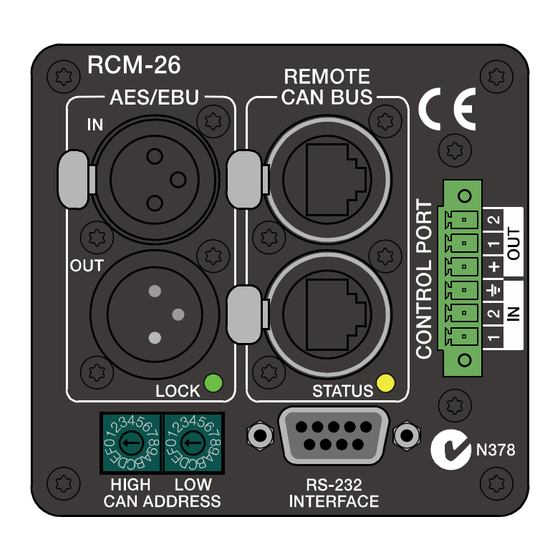
  • Page 54: Commandes Et Connexions

    2 Commandes et connexions 1, AES/EBU-IN Une entrée numérique AES/EBU (AES3) est fournie en plus des entrées analogiques internes. Le signal d’entrée numérique doit être relié au connecteur AES/EBU IN. L’entrée AES/EBU est isolée par un transformateur symétrisé. Un convertisseur de fréquence d’échantillonnage convertit le signal d’entrée pour qu’il corresponde à...
  • Page 55: 2, Aes/Ebu-Out

    externe existe aussi. Pour les détails, veuillez vous reporter aux fichiers d’aide IRIS-Net™. L’illustration suivante représente le câblage de la prise d’entrée. Illustration 2.1: Câblage de la prise AES/EBU-IN 2, AES/EBU-OUT Le connecteur AES/EBU OUT permet de transmettre le signal audio numérique à...
  • Page 56: 3, Témoin Lock

    3, Témoin LOCK Le témoin à LED “LOCK” s’allume en vert dès que l’entrée AES/ EBU s’est synchronisée au signal reçu et qu’une transmission audio est établie. Le témoin LOCK s’éteint quand aucun signal audio numérique n’est présent à l’entrée ou lorsque le PLL interne n’est pas verrouillé...
  • Page 57 Débit (en kbit/s) Longueur (en m) 62,5 1000 2500 5000 Tableau 1 : Débit et longueur du bus Illustration 2.3: Câblage de la prise CAN Illustration 2.4: Câblage de la prise CAN Fiche Couleur T568A T568B CAN_GND Vert Orange CAN_H (+) Bleu CAN_L (-) Rayé...
  • Page 58: 5, Témoin Status

    5, Témoin STATUS Le témoin à LED “STATUS” sert à surveiller la communication sur le bus CAN. La LED clignote en rythme toutes les 3 secondes, lorsque l’adresse du module est réglée sur “00“, ce qui signifie qu’il est déconnecté du bus CAN et donc du contrôle logiciel. La LED clignote en rythme toutes les secondes, lorsqu’une adresse comprise entre 01 et 250 a été...
  • Page 59 HIGH Adresse Indépendant 1...F 1...15 0...F 16...31 0...F 32...47 0...F 48...63 0...F 64...79 0...F 80...95 0...F 96...111 0...F 112...127 0...F 128...143 0...F 144...159 0...F 160...175 0...F 176...191 0...F 192...207 0...F 208...223 0...F 224...239 0...A 240...250 B...F réservé Tableau 3 : Adresses CAN L’adresse 0 (00 hex, état à...
  • Page 60: 7, Port De Controle

    7, PORT DE CONTROLE Le CONTROL PORT du RCM-26 fournit deux entrées de contrôle, deux sorties de contrôle et des connexions de référence pour le +5V et la terre. Les entrées de contrôle sont configurables via IRIS- Net™. Elles peuvent par exemple servir à passer du mode sous tension à...
  • Page 61 RS-232 servant à relier le RCM-26 à un autre appareil ne doit pas dépasser 15 mètres. Illustration 2.5: Câblage de l’Interface RS-232 Le tableau suivant montre les réglages d’usine de l’interface RS-232 du module RCM-26. L’appareil connecté (ex. un PC avec un logiciel de contrôle multi- media) doit être configuré...
  • Page 62: Principes Du Bus Can

    3 Principes du Bus CAN La topologie réseau utilisée par le bus CAN est basée sur une "topologie de chaîne ou de ligne", c'est-à-dire que tous les participants sont connectés via un seul câble à deux fils (paire torsadée, blindée ou pas), le câblage allant d'un participant au suivant sur le bus (ou chaîne), ce qui permet une communication illimitée entre les appareils.
  • Page 63 En employant un répétiteur de bus CAN une connexion entre deux systèmes de bus CAN indépendants peut être créée. Il est alors possible de: • Augmenter le nombre maximum de membres Un maximum de 100 appareils peuvent être connectés à un même bus CAN.
  • Page 64: Exemples De Systèmes

    Exemples de systèmes Les illustrations suivantes montrent des exemples de câblage de type bus de données pour différentes tailles de réseau CAN. Illustration 3.2: Système avec 5 amplis de puissance et un UCC-1 au début de la chaîne (bus). Bouchons de terminaison sur le UCC-1 (première unité du bus) et sur l'ampli 5 (dernière unité...
  • Page 65: Caractéristiques Des Performances

    Illustration 3.3: Système avec avec 2 amplis en rack et un UCC-1 au milieu. Bou- chons de terminaison sur l'ampli de puissance 6 (première unité du bus) et sur l'ampli de puissance 12 (dernière unité du bus) Caractéristiques des Performances Selon le standard ISO 11898-2, le câblage pour transfert de données du bus CAN doit être réalisé...
  • Page 66 bus. Le tableau suivant montre les exigences les plus essentielles pour les réseaux CAN composés d'un maximum de 64 participants. Câble de Transmission de données Longueur du- Terminaison Vitesse de Résistance par Diamètre du câble (en Ω) Bus (en m) Transfert Max.
  • Page 67 seule portion de câble ne doit pas dépasser 2 mètres. Pour des débits plus élevés une longueur maximum de seulement 0.3 mètre est permisse. La longueur totale de toutes les lignes de raccordement ne doit pas dépasser 30 mètres. Remarque générale: •...
  • Page 68: Appendix

    4 Appendix 4.1 Specifications/Technische Daten NETWORK AND GENERAL FEATURES Remote Control and Software IRIS-Net™, Multiple PCs possible, MS Win- dows 98, 2000, XP Maximum Configuration 250 Amplifiers in total, 100 Amplifiers per CAN bus, 1000 meter cable run Supervised Amplifier Parameters Operation mode, temperature, output volta- ge and current, impedance of connected speakers, protection mode status, mains voltage and current, power consumption, pi-...
  • Page 69 Frequency Response 20 Hz…40 kHz (-1.0 dB) Signal to Noise Ratio ADC: 120 dB typical (A-weighted) DAC: 118 dB typical AES3: 128 dB typical Analog In to Analog Out: 116 dB typical THD+N < 0.005 % Signal Delay 1.031 ms @ 96 kHz Crosstalk <...
  • Page 70: General Specifications

    GPIO Control Port 1 x 6-pole Euro block 2 Control Inputs 2 Control Outputs 2 Reference Outputs (+5 V, 200 mA / GND) RCM-26 GENERAL SPECIFICATIONS Supply Voltage/Current +5 V DC / 650 mA +15 V DC / 250 mA -15 V DC / 120 mA Power Consumption Operating Temperatur Range...
  • Page 71: Block Diagram / Blockschaltbild

    4.2 Block Diagram / Blockschaltbild DELAY RAM BYPASS OUT (A) Pre Fader IN (A) Post Fader ANALOG OUT ANALOG IN BYPASS Pre Fader OUT (B) IN (B) Post Fader Locked AES/EBU VMEAS (A) VMEAS (B) THRU CMEAS (A) Bypass CMEAS (B) REMOTE CAN BUS Monitor...
  • Page 72: Dimensions / Abmessungen

    4.3 Dimensions / Abmessungen RCM-26 Remote Control Module...
  • Page 73 RCM-26 Remote Control Module...
  • Page 74 Notes...
  • Page 75 Notes...
  • Page 76 USA: Telex Communications Inc. Germany: EVI Audio GmbH France: EVI Audio France 12000 Portland Ave. South Hirschberger Ring 45 Parc de Courcerin Burnsville D 94315 Straubing Allée Lech Walesa MN 55337 Germany 77185 Lognes Phone: +1 952-884-4051 Phone: +49 9421-706 0 France FAX: +1 952-884-0043 FAX: +49 9421-706 265...