ABB CM-TCS.11 Mode D'emploi
Masquer les pouces
Voir aussi pour CM-TCS.11:
Table des Matières
Liens rapides
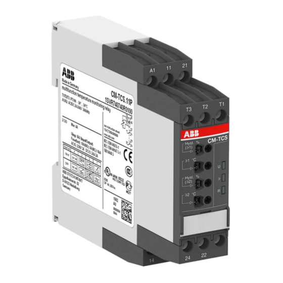
CM-TCS.11, CM-TCS.12, CM-TCS.13
CM-TCS.21, CM-TCS.22, CM-TCS.23
(D)
Betriebs- und Montageanleitung
Temperaturüberwachungsrelais, CM Reihe
Hinweis: Diese Betriebs- und Montageanleitung enthält nicht
sämtliche Detailinformationen zu allen Typen der Produktreihe
und kann auch nicht jeden Einsatzfall der Produkte berück-
sichtigen. Alle Angaben dienen ausschließlich der Produkt-
beschreibung und sind nicht als zugesicherte Eigenschaften
im Rechtssinne aufzufassen. Weiterführende Informationen
und Daten erhalten Sie in den Katalogen und Datenblättern
der Produkte, über die örtliche ABB-Niederlassung sowie auf
der ABB Homepage unter http://www.abb.com. Technische
Änderungen jederzeit vorbehalten. In Zweifelsfällen gilt der
deutsche Text.
Nur von einer entsprechend qualifizierten Fachkraft zu
installieren. Dabei landesspezifische Vorschriften (z.B.
VDE, etc.) beachten. Vor der Installation diese Be-
triebs- und Montageanleitung sorgfältig lesen und be-
achten. Die Geräte sind wartungsfreie Einbaugeräte.
(GB) Operating and installation instructions
Temperature monitoring relays, CM range
Note: These operating and installation instructions cannot
claim to contain all detailed information of all types of this
product range and can even not consider every possible ap-
plication of the products. All statements serve exclusively
to describe the product and have not to be understood as
assured characteristics with legal force. Further information
and data is obtainable from the catalogues and data sheets
of this product, from the local ABB sales organisations as
well as on the ABB homepage http://www.abb.com. Subject
to change without prior notice. The German text applies in
cases of doubt.
The device must be installed by qualified persons only
and in accordance with the specific national regula-
tions (e.g., VDE, etc.). Before installing this unit, read
these operating and installation instructions carefully
and completely. The devices are maintenance-free
chassis-mounted units.
ABB Stotz-Kontakt GmbH
Hauptstr. 14-16
78132 Hornberg / Germany
www.abb.com/lowvoltage -> Control Products -> Electronic Relays and Controls
(F)
Instructions de service et de montage
Relais de contrôle de température, gamme CM
Note: Ces instructions de service et de montage ne con-
tiennent pas toutes les informations relatives à tous les types
de cette gamme de produits et ne peuvent pas non plus
tenir compte de tous les cas d'application. Toutes les indi-
cations ne sont données qu'à titre de description du produit
et ne constituent aucunes obligations légales. Pour de plus
amples informations, veuillez-vous référer aux catalogues et
aux fiches techniques des produits, à votre agence ABB ou
à notre site http://www.abb.com. Sous réserve de modifica-
tions techniques. En cas de divergences, le texte allemand
fait foi.
L'installation de ces produits doit être réalisée uni-
quement par une personne compétente et en confor-
mité avec les prescriptions nationales (p.e. VDE,
etc.). Avant l'installation de cet appareil veuillez lire
l'intégralité de ces instructions. Ces produits sont
des appareils encliquetables qui ne nécessitent pas
d'entretien.
(E)
Instrucciones de servicio y de montaje
Relé de control de temperatura, serie CM
Nota: Estas instrucciones no contienen todas las informa-
ciones detalladas relativas a todos los tipos del producto ni
pueden considerar todos los casos de operación. Todas las
indicaciones son a título descriptivo del producto y no consti-
tuyen obligaciones legales. Para más información, consulte
los catálogos, las hojas de características, la sucursal local
de ABB o la Web http://www.abb.com. Sujeto a cambios
técnicos sin previo aviso. En caso de duda, prevalece el texto
alemán.
La instalación debe llevarse a cabo sólo por personal
especializado. Es necesario respetar las normas es-
pecificas del país (p.ej. VDE, etc.). Antes de la insta-
lación lea completamente estas instrucciones. Estos
aparatos son equipos para su montaje en conjuntos y
son de libre mantenimiento.
Table des Matières

Manuels Connexes pour ABB CM-TCS.11


Sommaire des Matières pour ABB CM-TCS.11
- Page 1 Daten erhalten Sie in den Katalogen und Datenblättern der Produkte, über die örtliche ABB-Niederlassung sowie auf aux fiches techniques des produits, à votre agence ABB ou der ABB Homepage unter http://www.abb.com. Technische à notre site http://www.abb.com. Sous réserve de modifica- Änderungen jederzeit vorbehalten.
- Page 2 filiale locale ABB. Ci riserviamo il diritto di effettuare eventuali mo- difiche tecniche. In caso di discrepanze o fraintendimenti fa fede il testo in lingua tedesca.
- Page 3 Produkt anbringen (GB) Fix product Montage du produit Fijar el producto Montare il prodotto (CN) (RU) Produkt entfernen (GB) Remove product Démontage du produit Desmontar el producto Rimuovere il prodotto (CN) (RU) Position i g r p Plombierbare Klarsichtabdeckung anbringen (GB) Fix sealable transparent cover Fixation du capot transparent condamnable Fijar cubierta transparente sellable...
- Page 4 T2 T3 24 V AC/DC 24-240 V AC/DC Bei Anschluss eines Zweileitersensors die Klemmen T2 und T3 brücken. Galvanische Trennung When connecting a two-wire sensor, jumper the terminals T2 Electrical isolation and T3 Isolation galvanique Si raccordement d‘un détecteur bifilaire, ponter les bornes T2 et T3 Aislamiento eléctrico Cuando se conecta un sensor a dos hilos, puentear los termi-...
- Page 5 Frontansicht mit Bedienelementen Front view with operating controls Deutsch English Betriebszustandsanzeige mit LEDs Indication of operational states with LEDs U: LED grün - Anzeige Steuerspeisespannung U: green LED - Status indication of control supply t: LED rot - Fehlermeldung, Status Messeingang voltage t: red LED R: LED gelb...
- Page 6 Face avant et dispositifs de commande Vistas frontales con elementos de mando Français Español Indication de fonctionnement par LED Indicadores de servicio con LEDs U: LED verte - Indication de la tension d‘alimentation U: LED verde - Indicación tensión de alimentación de de commande mando t: LED rouge...
- Page 7 Vista frontale con gli elementi di comando Italiano LED di visualizzazione dello stato di funzionamento U: LED verde - Indicazione tensione di comando t: LED rosso - Messaggio d‘errore, stato dell‘ingresso di misura R: LED giallo - Indicazione dello stato dei relè di uscita Impostazione della isteresi per il valore di soglia t1 Impostazione del valore di soglia t1 Impostazione della isteresi per il valore di soglia t2...
- Page 9 IV Function diagrams a) Overtemperature monitoring, 1 x 2 c/o d) Undertemperature monitoring, 2 x 1 c/o A1-A2 A1-A2 Threshold ϑ1 Measured value Hysteresis Hysteresis Threshold ϑ1 Measured value Open-circuit Hysteresis principle 11-14 Threshold ϑ2 11-12 Open-circuit 21-24 principle 21-22 11-14 U: green LED 11-12...
- Page 10 V Funktionsdiagramme Deutsch Untertemperaturüberwachung, 2 x 1 Wechsler a) Übertemperaturüberwachung p, 1 x 2 Wechsler j Arbeitsstromprinzip: b) Übertemperaturüberwachung p, 2 x 1 Wechsler i Wird die Steuerspeisespannung angelegt, bleiben die Ausgangsre- c) Untertemperaturüberwachung q, 1 x 2 Wechsler j lais bei korrektem Messwert in ihrer Ruhestellung.
-
Page 11: Function Diagrams
VI Function diagrams English Undertemperature monitoring, 2 x 1 c/o contact a) Overtemperature monitoring p, 1 x 2 c/o contacts j Open-circuit principle: b) Overtemperature monitoring p, 2 x 1 c/o contact i If the measured value is correct, the output relays remain de-ener- c) Undertemperature monitoring q, 1 x 2 c/o contacts j gized when control supply voltage is applied. -
Page 12: Diagrammes De Fonctionnement
V Diagrammes de fonctionnement Français Fonctionnement en logique négative: a) Contrôle de température excessive p, 1 x 2 inverseurs j Le comportement des relais est l‘inverse du fonctionnement en b) Contrôle de température excessive p, 2 x 1 inverseur i logique positive. -
Page 13: Diagramas De Funcionamiento
V Diagramas de funcionamiento Español Principio de circuito abierto: a) Control de temperatura excesiva p, Cuando se aplica la tensión de alimentación de mando y con 1 x 2 contactos conmutados j el valor medido correcto, los relés de salida permanecen des- b) Control de temperatura excesiva p, energizados. -
Page 14: Principio Di Funzionamento
V Diagrammi di funzionamento Italiano Se il valore misurato scende sotto il valore di soglia t2 impostato, a) Controllo di sovratemperatura p, i relè di uscita si eccitano. Se il valore misurato supera di nuovo il valore di soglia t2 più l‘isteresi, i relè di uscita si diseccitano. 1 x 2 contatti di scambio j b) Controllo di sovratemperatura p, Funzionamento normalmente chiuso:...