Riello Burners RS 45/M BLU Manuel D'entretien
Masquer les pouces
Voir aussi pour RS 45/M BLU:
- Mode d'emploi (42 pages) ,
- Manuel d'entretien (40 pages)
Table des Matières
Publicité
Liens rapides
Istruzioni per installazione, uso e manutenzione
Montage und Bedienungs Anleitung
Installation, use and maintenance instructions
Manuel d'entretien
Bruciatori di gas ad aria soffiata
I
Gebläse - Gasbrenner
D
Forced draught gas burners
GB
Brûleurs gaz à air soufflé
F
Funzionamento bistadio progressivo o modulante
Zweistufig gleitender oder modulierender Betrieb
Progressive two-stage or modulating operation
Fonctionnement à deux allures progressives ou modulant
CODICE - CODE
3897312
3897313
MODELLO - MODELL
MODEL - MODELE
RS 45/M BLU
RS 45/M BLU
TIPO - TYP
TYPE - TYPE
827 T2
827 T2
2915753 (3)
Publicité
Table des Matières

Manuels Connexes pour Riello Burners RS 45/M BLU


Sommaire des Matières pour Riello Burners RS 45/M BLU
- Page 1 Progressive two-stage or modulating operation Fonctionnement à deux allures progressives ou modulant MODELLO - MODELL TIPO - TYP CODICE - CODE MODEL - MODELE TYPE - TYPE 3897312 RS 45/M BLU 827 T2 3897313 RS 45/M BLU 827 T2 2915753 (3)
-
Page 2: Table Des Matières
INDICE INHALT DATI TECNICI ....... . . pagina 4 TECHNISCHE ANGABEN ......Seite 5 Accessori . -
Page 3: Dati Tecnici
DATI TECNICI MODELLO RS 45/M BLU TIPO 827 T2 190 - 550 MAX. 164 - 474 Mcal/h POTENZA MIN. Mcal/h COMBUSTIBILE GAS NATURALE: G20 - G21 - G22 - G23 - G25 kWh/Nm - Potere calorifico inferiore Mcal/Nm - Densità assoluta... -
Page 4: Technische Angaben
TECHNISCHE ANGABEN MODELL RS 45/M BLU 827 T2 190 - 550 MAX. 164 - 474 Mcal/h LEISTUNG MIN. Mcal/h BRENNSTOFF ERDGAS: G20 - G21 - G22 - G23 - G25 kWh/Nm - Unterer Heizwert Hu Mcal/Nm - Reindichte 0,71 0,78 kg/Nm - Höchstdurchsatz... -
Page 5: Technical Data
TECHNICAL DATA MODEL RS 45/M BLU TYPE 827 T2 190 - 550 MAX. 164 - 474 Mcal/h OUTPUT MIN. Mcal/h FUEL NATURAL GAS: G20 - G21 - G22 - G23 - G25 kWh/Nm - Net calorific value Mcal/Nm - Absolute density... -
Page 6: Donnees Techniques
DONNEES TECHNIQUES MODELE RS 45/M BLU TYPE 827 T2 190 - 550 MAX. 164 - 474 Mcal/h PUISSANCE MIN. Mcal/h COMBUSTIBLE GAZ NATUREL: G20 - G21 - G22 - G23 - G25 kWh/Nm - Pouvoir calorifique inférieur Mcal/Nm - Densité absolue... -
Page 7: Descrizione Bruciatore
- misure indicative • I bruciatori vengono spediti in imballi di car- tone con dimensioni di ingombro secondo tabella (B). • Il peso del bruciatore completo di imballo è RS 45/M BLU 1015 indicato nella tabella (B). INGOMBRO (C) - misure indicative L'ingombro del bruciatore è... -
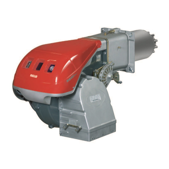
Page 8: Burner Description
BRENNERBESCHREIBUNG (A) BURNER DESCRIPTION (A) DESCRIPTION BRULEUR (A) 1 Flammkopf 1 Combustion head 1 Tête de combustion 2 Zündelektrode 2 Ignition electrode 2 Electrode d'allumage 3 Einstellschraube des Flammkopfes 3 Screw for combustion head adjustment 3 Vis pour réglage tête de combustion 4 Gas-Höchstdruckwächter 4 Max. -
Page 9: Campo Di Lavoro
CALDAIE COMMERCIALI (C) - IMPOR- TANTE Il bruciatore RS 45/M BLU è adatto per funzio- nare sia su caldaie ad inversione di fiamma, sia su caldaie con camera di combustione a deflusso dal fondo (tre giri di fumo) sulle quali si... -
Page 10: Firing Rate
Le brûleur RS 45/M BLU peut fonctionner sur Der Brenner RS 45/M BLU ist für den Betrieb so- the base (three flue passes) on which the best des chaudières avec inversion de flamme ou à... -
Page 11: Pressione Gas
PRESSIONE GAS ∆p (mbar) RS 45/M BLU La tabella a lato indica le perdite di carico minime lungo la linea di alimentazione del gas in funzione della potenza massima del bruciatore. Ø 1”1/4 Ø 1”1/2 Ø 2” Ø 2” Ø 3/4”... -
Page 12: Gas Pressure
GASDRUCK GAS PRESSURE PRESSION DU GAZ In der nebenstehenden Tabelle werden die Min- The adjacent table shows minimum pressure Le tableau ci-contre indique les pertes de destströmungsverluste entlang der Gaszulei- losses along the gas supply line depending on charge minimales sur la ligne d'alimentation en tung iin Abhängigkeit von der Höchstleistung the maximum burner output operation. -
Page 13: Installazione
Forare la piastra di chiusura della camera di combustione come in (A). La posizione dei fori filettati può essere tracciata utilizzando lo RS 45/M BLU schermo termico a corredo del bruciatore. LUNGHEZZA BOCCAGLIO (B) La lunghezza del boccaglio deve essere mag- giore dello spessore della porta della caldaia, completa di refrattario. -
Page 14: Installation
Material sein. Die Längen, (mm), sind: with its fettling. The lengths, L (mm), are: réfractaire compris. Les longueurs, L (mm), sont: Flammrohr 10): RS 45/M BLU Blast tube 10): RS 45/M BLU • kurz • short... -
Page 15: Regolazione Testa Di Combustione
REGOLAZIONE TESTA COMBU- STIONE A questo punto dell’installazione, boccaglio e manicotto sono fissati alla caldaia come in fig. (A). È quindi particolarmente agevole la regola- zione delle testa di combustione, regolazione che dipende unicamente dalla potenza massima del bruciatore. Perciò, prima di regolare la testa di combu- stione, bisogna fissare questo valore. -
Page 16: Combustion Head Setting
EINSTELLUNG DES FLAMMKOPFS COMBUSTION HEAD SETTING REGLAGE TETE DE COMBUSTION An dieser Stelle der Installation sind Flammrohr Installation operations are now at the stage A ce stade de l'installation, la buse et le man- und Muffe gem. Abb. (A) am Kessel befestigt. where the blast tube and sleeve are secured to chon sont fixésà... -
Page 17: Linea Alimentazione Gas
LINEA ALIMENTAZIONE GAS • La rampa del gas va collegata all'attacco del gas 1)(A), tramite la flangia 2), la guarnizione 3) e le viti 4) date a corredo del bruciatore stesso. • La rampa può arrivare da destra o da sinistra, secondo comodità, vedi fig. -
Page 18: Gas Line
GASZULEITUNG GAS LINE LIGNE ALIMENTATION GAZ • Gasarmaturen sind über Flansch 2), Dichtung • The gas train must be connected to the gas • La rampe du gaz doit être reliée au raccord 3) und Schrauben 4), zur Brennerausstattung attachment 1)(A), using flange 2), gasket 3) correspondant 1)(A), par la bride 2), le joint 3) gehörend, mit dem Gasanschluß... -
Page 19: Impianto Elettrico
IMPIANTO ELETTRICO eseguito in fabbrica IMPIANTO ELETTRICO ESEGUITO IN FABBRICA WERKSEITIG AUSGEFÜHRTE ELEKTROANLAGE Legenda schema (A) FACTORY SET ELECTRICAL SYSTEM INSTALLATION ELECTRIQUE REALISEE EN USINE - Condensatore - Filtro contro radiodisturbi LGK16.. - Apparecchiatura elettrica - Morsettiera bruciatore - Motore ventilatore - Pressostato aria - Pressostato gas di massima - Interruttore per funzionamento:... -
Page 20: Electrical System
ELEKTROANLAGE ELECTRICAL SYSTEM INSTALLATION ELECTRIQUE werkseitig ausgeführt as set by the man- réalisée en ufacturer usine Zeichenerklärung Schema (A) Key to Layout (A) Légende schéma (A) - Kondensator - Capacitor - Condensateur - Entstörer - Protection against radio interference - Protection contre parasites radio LGK16.. - Page 21 COLLEGAMENTI ELETTRICI Usare cavi flessibili secondo norma EN 60 335-1: • se sotto guaina di PVC almeno tipo H05 VV-F; • se sotto guaina di gomma almeno tipo H05 RR-F. Tutti i cavi da collegare alle spine 7)(A) del bru- ciatore vanno fatti passare dai passacavi forniti a corredo da inserire nei fori della piastrina, di destra o di sinistra, dopo aver svitato le viti 8),...
- Page 22 5- Pg 11 Pressostat gaz ou contrôle d'étan- LAYOUT (B) chéité vannes gaz SCHEMA (B) The RS 45/M BLU Models electrical connec- Elektroanschluß der Brenner RS 45/M BLU tion without leak detection control device. SCHEMA (B) ohne Dichtheitskontrolle der Gasventile.
- Page 23 SCHEMA (A) Allacciamento regolatore di potenza RWF40 e relativa sonda al bruciatore RS 45/M BLU (funzionamento modulante) Note I telecomandi TR e TL non sono necessari quando è collegato il RWF40 per funzionamento modu- lante; la loro funzione viene svolta dal regolatore stesso.
- Page 24 Connection of RWF40 output governor and Branchement électrique régulateur de puis- und des entsprechenden Fühlers an den Bren- related probe to RS 45/M BLU burner (modu- sance RWF40 et sonde correspondante au ner RS 45/M BLU (modulierender Betrieb) lating operation) brûleur RS 45/M BLU (fonctionnement modu-...
-
Page 25: Regolazioni Prima Dell'accensione
REGOLAZIONI PRIMA DELL'ACCENSIONE PRESSOSTATO GAS DI MIN. PRESSOSTATO GAS DI MAX. La regolazione della testa di combustione, aria e PRESSOSTATO ARIA gas, è già stata descritta a pag. 16. GAS-MINDESTDRUCKWÄCHTER GAS-HÖCHSTDRUCKWÄCHTER LUFT-DRUCKWÄCHTER Altre regolazioni da fare sono: MIN GAS PRESSURE SWITCH MAX GAS PRESSURE SWITCH AIR PRESSURE SWITCH - aprire le valvole manuali poste a monte della... -
Page 26: Adjustments Before Firing
EINSTELLUNGEN VOR DER ZÜNDUNG ADJUSTMENTS BEFORE FIRST FIRING REGLAGES AVANT L'ALLUMAGE Die Einstellung des Flammkopfs, von Luft und Le réglage de la tête de combustion, air et gaz, Adjustment of the combustion head, and air and Gas, ist bereits auf Seite 17 beschrieben worden. a déjà... -
Page 27: Regolazione Bruciatore
REGOLAZIONE BRUCIATORE Per ottenere una regolazione ottimale del bru- ciatore è necessario effettuare l'analisi dei gas di scarico della combustione all'uscita della cal- daia. Regolare in successione: 1 - Potenza all’accensione 2 - Potenza MAX 3 - Potenza MIN 4 - Potenze intermedie tra le due 5 - Pressostato aria D791 6 - Pressostato gas di massima... -
Page 28: Burner Calibration
BRENNEREINSTELLUNG BURNER CALIBRATION REGLAGE BRULEUR Pour obtenir un réglage optimal du brûleur, il Für die optimale Einstellung des Brenners soll- The optimum calibration of the burner requires faut effectuer l’analyse des gaz de combustion ten die Abgase am Kesselausgang analysiert an analysis of the flue gases at the boiler outlet. -
Page 29: Potenza Minima
Regolazione dell'aria Variare in progressione il profilo finale della camma 4)(A) agendo sulle viti della camma che compaiono all’interno dell’apertura 6)(A). - Per aumentare la portata d’aria avvitare le viti. - Per diminuire la portata d’aria svitare le viti. 3 - POTENZA MIN La potenza MIN va scelta entro il campo di lavoro riportato a pag. -
Page 30: Minimum Output
Lufteinstellung Adjusting air delivery Réglage air Über die Schrauben des Nocken im Inneren der Progressively adjust the end profile of cam 4)(A) Modifier en progression le profil final de la came Öffnung 6) (A) das Endprofil des Nocken 4)(A) 4)(A) en agissant sur les vis de celle-ci qui by turning the cam adjustment screws as they apparaissent à... -
Page 31: Pressostato Aria
5 - PRESSOSTATO ARIA (A) PRESSOSTATO ARIA 15)(A)p. 8 Il pressostato aria è collegato in modo differen- LUFT-DRUCKWÄCHTER 15)(A)S. 8 ziale, vedi 1)(A), cioè è sollecitato sia dalla AIR PRESSURE SWITCH 15)(A)p. 8 depressione che dalla pressione generate dal PRESSOSTAT AIR 15)(A)p. 8 ventilatore. -
Page 32: Air Pressure Switch
5 - LUFTDRUCKWÄCHTER (A) 5 - AIR PRESSURE SWITCH (A) 5 - PRESSOSTAT DE L'AIR (A) Le pressostat de l’air est relié de façon différen- Der Luft-Druckwächter (Differentialtyp) wird The air pressure switch is differentially con- tielle, voir 1)(A), c’est-à-dire qu’il est sollicité durch den Unterdruck und den Druck des nected, see 1)(A), it is activated by both the neg- aussi bien par la dépression que par la pression... -
Page 33: Funzionamento Bruciatore
FUNZIONAMENTO BRUCIATORE ACCENSIONE REGOLARE ORDNUNGSGEMÄSSES AVVIAMENTO BRUCIATORE (A) (n° = secondi dall’istante 0) (n° = Sekunden ab Zeitpunkt 0) • 0s: Chiusura telecomando TL. NORMAL FIRING ALLUMAGE REGULIER Avvio motore ventilatore. (n° = seconds from istant 0) (n° = secondes à partir de l’istant 0) •... -
Page 34: Burner Operation
BRENNERBETRIEB BURNER OPERATION FONCTIONNEMENT BRULEUR DEMARRAGE BRULEUR (A) ANFAHREN DES BRENNERS (A) BURNER STARTING (A) • 0s: Fermeture télécommande TL. • 0s: Abschalten Fernsteuerung TL. • 0s: Load control TL closes. Démarrage moteur ventilateur. Anfahren Gebläsemotor. Fan motor starts. • 6s: Démarrage servomoteur: •... -
Page 35: Controlli Finali
CONTROLLI FINALI (con bruciatore funzio- VISORE FIAMMA - SICHTFENSTER FLAMME nante) FLAME INSPECTION WINDOW - VISEUR FLAMME • Scollegare un filo del pressostato gas di minima: • Aprire il telecomando TL: • Aprire il telecomando TS: il bruciatore deve fermarsi •... -
Page 36: Final Checks
ENDKONTROLLEN FINAL CHECKS CONTROLES FINAUX (bei Brenner in Betrieb) (with burner running) (brûleur en fonction- • Einen Draht des Gas-Mindestdruckwächters nement) • Disconnect one of the wires on the minimum abtrennen: • Débrancher un fil du pressostat de seuil mini- gas pressure switch: •... -
Page 37: Inconvenienti - Cause - Rimedi
SIMBOLO INCONVENIENTE CAUSA PROBABILE RIMEDIO CONSIGLIATO Il bruciatore non si avvia - Manca l'energia elettrica ......Chiudere interruttori - Controllare collegamenti - Un telecomando di limite o di sicurezza aperto. -
Page 38: Störungen - Ursachen - Abhilfen
ZEICHEN STÖRUNGEN MÖGLICHE URSACHEN EMPFOHLENE ABHILFEN Brenner läuft nicht an - Kein Strom........Schalter schließen - Anschlüsse kontrollieren - Eine Grenz- oder Sicherheitsregelung offen . -
Page 39: Fault - Probable Cause - Suggested Remedy
SYMBOL FAULT PROBABLE CAUSE SUGGESTED REMEDY The burner does not start - No electrical power supply ......Close all switches - Check connections - A limiter or safety control device is open. -
Page 40: Inconvénients - Causes - Rimèdes
SYMBOLE INCONVENIENT CAUSE PROBABLE REMEDE CONSEILLE Le brûleur ne démarre pas - Absence de courant électrique ..... . Fermer interrupteurs - éontrôler fusibles - Une télécommande de limite ou de sécurité...