Danfoss VLT Micro Drive FC 51 Guide Rapide
Masquer les pouces
Voir aussi pour VLT Micro Drive FC 51:
- Guide rapide (168 pages) ,
- Instructions de montage (93 pages) ,
- Guide de programmation (91 pages)

Manuels Connexes pour Danfoss VLT Micro Drive FC 51


Sommaire des Matières pour Danfoss VLT Micro Drive FC 51
- Page 1 ENGINEERING TOMORROW Quick Guide • Kurzanleitung • Guide rapide • Guíarápida • Guia Rápido • Краткое руководство ® Micro Drive FC 51 vlt-drives.danfoss.com...
-
Page 5: Table Des Matières
2 Kurzanleitung 2.1 Einführung 2.1.1 Zielsetzung des Handbuchs 2.1.2 Zusätzliche Materialien 2.1.3 IT-Netz 2.1.4 Unerwarteten Anlauf vermeiden 2.2 Sicherheit 2.3 Installation 2.3.1 Seite-an-Seite-Installation 2.3.2 Mechanische Abmessungen 2.3.3 Netz- und Motoranschluss 2.3.4 Steuerklemmen MG02BC4P Danfoss A/S © 10/2017 All rights reserved. - Page 6 3.7 Spécifications 3.8 Caractéristiques techniques générales 3.9 Exigences particulières 3.9.1 Déclassement pour température ambiante 3.9.2 Déclassement pour basse pression atmosphérique 3.9.3 Déclassement pour fonctionnement à faible vitesse 3.10 Options et pièces détachées Danfoss A/S © 10/2017 All rights reserved. MG02BC4P...
- Page 7 5.1.4 Evite partida acidental 5.2 Segurança 5.3 Instalação 5.3.1 Instalação lado a lado 5.3.2 Dimensões mecânicas 5.3.3 Conexão na Rede Elétrica e Motor 5.3.4 Terminais de Controle 5.3.5 Circuito de Alimentação - Visão Geral MG02BC4P Danfoss A/S © 10/2017 All rights reserved.
- Page 8 6.8 Общие технические данные 6.9 Особые условия 6.9.1 Снижение номинальных характеристик в зависимости от температуры окружающей среды 6.9.2 Снижение номинальных параметров в случае низкого атмосферного давления 6.9.3 Снижение номинальных параметров при работе на низких скоростях Danfoss A/S © 10/2017 All rights reserved. MG02BC4P...
- Page 9 Quick Guide•Kurzanleitung•Guide rapide•Guía rápida•Guia Rápido•Краткое Contents руководство 6.10 Дополнительные устройства и запасные части Index MG02BC4P Danfoss A/S © 10/2017 All rights reserved.
-
Page 10: Quick Guide
440 V. Always keep this quick guide with the frequency converter. As an option, Danfoss offers recommended line filters for ® is a registered trademark. improved harmonics performance. See Table 1.11. -
Page 11: Safety
Reinforce Grounding in 1 of the following ways: • Grounding wire of at least 10 mm (8 AWG). • 2 separate ground wires both complying with the dimensioning rules. See EN 60364-5-54 § 543.7 for further information. MG02BC4P Danfoss A/S © 10/2017 All rights reserved. -
Page 12: Safety Instructions
1-90 Motor Thermal Protection to [4] ETR trip. For the North American market: Implemented ETR function provides class 20 motor overload protection, in accordance with NEC. Installation at high altitudes For altitudes above 2000 m (6562 ft), contact Danfoss regarding PELV. 1.2.1 Safety Instructions •... -
Page 13: Mechanical Dimensions
1) For LCP with potentiometer, add 7.6 mm (0.3 in). NOTICE All cabling must comply with national and local regulations on cable cross-sections and ambient temperature. Copper conductors required, 60–75 °C (140–167 °F) recommended. MG02BC4P Danfoss A/S © 10/2017 All rights reserved. - Page 14 3 (26.6) (15–20) (11.5) (11.5) (4.4) 18.5–22.0 – – 1.3 (11.5) 0.15 (1.3) 3 (26.6) (25–30) (11.5) (11.5) (4.4) Table 1.3 Tightening of Terminals 1) Spade connectors (6.3 mm (0.25 in) Faston plugs). Danfoss A/S © 10/2017 All rights reserved. MG02BC4P...
- Page 15 A6K-40R 11K0 KTS-R60 JKS-60 JJS-60 KLS-R60 – A6K-60R 15K0 KTS-R60 JKS-60 JJS-60 KLS-R60 – A6K-60R 18K5 KTS-R60 JKS-60 JJS-60 KLS-R60 – A6K-60R 22K0 KTS-R60 JKS-60 JJS-60 KLS-R60 – A6K-60R Table 1.4 Fuses MG02BC4P Danfoss A/S © 10/2017 All rights reserved.
-
Page 16: Connecting To Mains And Motor
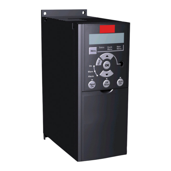
(terminal 53 or 60) make the frequency converter terminals and switches. run. Do not operate switches with power on the frequency converter. Set parameter 6-19 Terminal 53 Mode according to Switch 4 position. Danfoss A/S © 10/2017 All rights reserved. MG02BC4P... - Page 17 Quick Guide•Kurzanleitung•Guide rapide•Guía rápida•Guia Rápido•Краткое Quick Guide руководство Illustration 1.5 Overview of Control Terminals in PNP-configuration with Factory Setting MG02BC4P Danfoss A/S © 10/2017 All rights reserved.
-
Page 18: Power Circuit - Overview
Improved power factor and EMC performance can be achieved by installing optional Danfoss line filters. ® Danfoss power filters can also be used for load sharing. For more information about load sharing, see VLT FC 51 Micro Drive Load Sharing application note. -
Page 19: Load Sharing/Brake
Use 6.3 mm (0.25 in) insulated Faston plugs designed for Status high voltage for DC (load sharing and brake). For readouts only. ® Contact Danfoss or see Load sharing instruction VLT 5000 Quick Menu ® for load sharing and VLT 2800/5000/5000 FLUX/FCD 300 For access to Quick Menus 1 and 2. - Page 20 The test runs automatically and indicates when it is complete. is complete. NOTICE In mode 2, the rotor rotates during the AMT progress. Do not add any load on motor in this AMT progress. Danfoss A/S © 10/2017 All rights reserved. MG02BC4P...
-
Page 21: Parameter Overview
1-80 Function at Stop [1] -Max - +Max 0-60 (Main) Menu Password *[0] Coast 3-02 Minimum Reference 0–999 *0 [1] DC hold -4999–4999 *0.000 3-03 Maximum Reference -4999–4999 *50.00 1) M4 and M5 only MG02BC4P Danfoss A/S © 10/2017 All rights reserved. - Page 22 3-52 Ramp 2 Ramp down Time Constant 0.05–3600 s *3.00 s (10.00 s 0.01–10.00 s *0.01 s 3-8* Other Ramps 3-80 Jog Ramp Time 0.05–3600 s *3.00 s (10.00s 1) M4 and M5 only Danfoss A/S © 10/2017 All rights reserved. MG02BC4P...
- Page 23 13-03 Reset SLC [8] PulseInput33 [4] 38400 Baud *[3] LogicOr *[0] Do not reset [11] LocalBusRef 8-51 Quick Stop Select [1] Reset SLC 7-3* Process PI See par. 8-50 * [3] LogicOr MG02BC4P Danfoss A/S © 10/2017 All rights reserved.
- Page 24 [14] Reset at power up 16-03 Status Word 0.000–99.990 ohm *0.000 ohm 14-21 Automatic Restart Time 0–0XFFFF 18-81 Stator Leakage 0–600s * 10s 16-05 Main Actual Value [%] Reactance(High resolution) -200.0–200.0% *0.0% 0.000–99.990 ohm *0.000 ohm Danfoss A/S © 10/2017 All rights reserved. MG02BC4P...
-
Page 25: Troubleshooting
An error occurred while copying from frequency converter to LCP, or from LCP to frequency converter. LCP data invalid Occurs when copying from LCP if the LCP contains erroneous data - or if no data was uploaded to the LCP. MG02BC4P Danfoss A/S © 10/2017 All rights reserved. - Page 26 Occurs when using a wrong password for changing a entered password-protected parameter. 1) These faults are caused by mains distortions. Install a Danfoss line filter to rectify this problem. Table 1.6 Warnings and Alarms Code List Danfoss A/S © 10/2017 All rights reserved.
-
Page 27: Specifications
LCP and typical control card power consumptions are included. For power loss data according to EN 50598-2, refer to drives.danfoss.com/knowledge-center/energy-efficiency-directive/#/. 2) Efficiency measured at nominal current. For energy efficiency class, see chapter 1.8.1 Surroundings. For part load losses, see drives.danfoss.com/ knowledge-center/energy-efficiency-directive/#/. - Page 28 LCP and typical control card power consumptions are included. For power loss data according to EN 50598-2, refer to drives.danfoss.com/knowledge-center/energy-efficiency-directive/#/. 2) Efficiency measured at nominal current. For energy efficiency class, see chapter 1.8.1 Surroundings. For part load losses, see drives.danfoss.com/ knowledge-center/energy-efficiency-directive/#/.
- Page 29 81.5 101.6 133.5 Best case/typical Weight enclosure IP20 [kg] Efficiency [%] 96.8/ 97.4/ 98.0/ 97.9/ 98.0/ 98.0/ 95.5 96.0 97.2 97.1 97.2 97.3 Best case/typical Table 1.9 Mains Supply 3x380–480 V AC MG02BC4P Danfoss A/S © 10/2017 All rights reserved.
- Page 30 LCP and typical control card power consumptions are included. For power loss data according to EN 50598-2, refer to drives.danfoss.com/knowledge-center/energy-efficiency-directive/#/. 2) Efficiency measured at nominal current. For energy efficiency class, see chapter 1.8.1 Surroundings. For part load losses, see drives.danfoss.com/ knowledge-center/energy-efficiency-directive/#/.
-
Page 31: General Technical Data
/18 AWG Maximum cross-section to control terminals, cable with enclosed core 0.5 mm /20 AWG Minimum cross-section to control terminals 0.25 mm (24 AWG) 1) See chapter 1.7 Specifications for more information. MG02BC4P Danfoss A/S © 10/2017 All rights reserved. - Page 32 Common for terminals 68 and 69 Control card, 24 V DC output Terminal number Maximum load (M1 and M2) 100 mA Maximum load (M3) 50 mA Maximum load (M4 and M5) 80 mA Danfoss A/S © 10/2017 All rights reserved. MG02BC4P...
- Page 33 Derating for high ambient temperature. • Derating for high altitude. 2) Determined according to EN 50598-2 at: • Rated load. • 90% rated frequency. • Switching frequency factory setting. • Switching pattern factory setting. MG02BC4P Danfoss A/S © 10/2017 All rights reserved.
-
Page 34: Special Conditions
1.9.2 Derating for Low Air Pressure The cooling capability of air is decreased at low air pressure. CAUTION INSTALLATION AT HIGH ALTITUDE For altitudes above 2000 m (6560 ft), contact Danfoss regarding PELV. Danfoss A/S © 10/2017 All rights reserved. MG02BC4P... -
Page 35: Options And Spare Parts
130B2528 ® Line Filter MCC 107 for 132F0028 130B2527 ® Line Filter MCC 107 for 132F0030 Table 1.11 Options and Spare Parts Danfoss line filters and brake resistors are available upon request. MG02BC4P Danfoss A/S © 10/2017 All rights reserved. -
Page 36: Kurzanleitung
Beachten Sie insbesondere die Sicherheitshinweise und chluss: 440 V. allgemeinen Warnungen. Bewahren Sie diese Bedienung- sanleitung immer zusammen mit dem Frequenzumrichter Danfoss bietet als Option Netzfilter für verbesserte auf. Reduzierung von Oberwellen an. Siehe Table 1.11. ® ist eine eingetragene Marke. -
Page 37: Sicherheit
Sie trennt den Frequenzumrichter kondensatoren laden und einen transienten Erdstrom nicht vom Netz. verursachen kann. Der Erdableitstrom hängt von verschiedenen Faktoren bei der Systemkonfiguration ab, wie EMV-Filter, abgeschirmte Motorkabel und Leistung des Frequenzumrichters. MG02BC4P Danfoss A/S © 10/2017 All rights reserved. -
Page 38: Sicherheitshinweise
Vorschriften gegen Überlast. • Der Erdableitstrom übersteigt 3,5 mA. Erden Sie den Frequenzumrichter ordnungsgemäß. • Sie können die Taste [Off/Reset] nicht als Sicher- heitsschalter benutzen. Sie trennt den Frequenzumrichter nicht vom Netz. Danfoss A/S © 10/2017 All rights reserved. MG02BC4P... -
Page 39: Mechanische Abmessungen
1) Fügen Sie bei einem LCP mit Potentiometer 7,6 mm (0,3 Zoll) hinzu. NOTICE Befolgen Sie stets die nationalen und lokalen Vorschriften zum Leitungsquerschnitt und zur Umgebungstemperatur. Kupferleiter erforderlich, 60–75 °C (140–167 °F) empfohlen. MG02BC4P Danfoss A/S © 10/2017 All rights reserved. - Page 40 KLN-R25 ATM-R25 A2K-25R KTN-R40 JKS-40 JJN-40 KLN-R40 ATM-R40 A2K-40R KTN-R40 JKS-40 JJN-40 KLN-R40 – A2K-40R 3 x 380–480 V 0K37–0K75 KTS-R10 JKS-10 JJS-10 KLS-R10 ATM-R10 A6K-10R KTS-R15 JKS-15 JJS-15 KLS-R15 ATM-R15 A2K-15R Danfoss A/S © 10/2017 All rights reserved. MG02BC4P...
-
Page 41: Netz- Und Motoranschluss
Illustration 2.2 Befestigung von Erdkabel, Netz- und ® Micro Drive FC 51 Abschirmblech und Motorkabeln Montageplatte. • Ziehen Sie ebenfalls die EMV-gerechte Installation ® im VLT Micro Drive FC 51 Projektierung- shandbuch zurate. MG02BC4P Danfoss A/S © 10/2017 All rights reserved. -
Page 42: Steuerklemmen
Illustration 1.5 zeigt alle Steuerklemmen des Frequenzum- richters. Durch Anlegen eines Startbefehls (Klemme 18) und eines Analogsollwerts (Klemme 53 oder 60) versetzen Sie den Frequenzumrichter in den Betriebszustand. Illustration 2.3 Entfernen der Klemmenabdeckung Danfoss A/S © 10/2017 All rights reserved. MG02BC4P... - Page 43 Quick Guide•Kurzanleitung•Guide rapide•Guía rápida•Guia Rápido•Краткое Kurzanleitung руководство Illustration 2.5 Übersicht von Steuerklemmen in PNP-Konfiguration mit Werkseinstellung MG02BC4P Danfoss A/S © 10/2017 All rights reserved.
-
Page 44: Elektrische Installation - Übersicht
® Weitere Informationen zu Bremswiderständen finden Sie im Projektierungshandbuch VLT Brake Resistor MCE 101. Eine Verbesserung des Leistungsfaktors und der EMV-Leistung ist durch Einbau optionaler Danfoss-Netzfilter möglich. Danfoss-Leistungsfilter können ebenfalls zur Zwischenkreiskopplung eingesetzt werden. Weitere Informationen zur ® Zwischenkreiskopplung entnehmen Sie dem Anwendungshinweis VLT FC 51 Micro Drive Zwischenkreiskopplung. -
Page 45: Zwischenkreiskopplung/Bremse
Bremse) isolierte, für Parameter Unit Hochspannungsanwendungen geeignete 6,3-mm-Faston- number Stecker. Selected Motor menu Weitere Informationen erhalten Sie bei Danfoss oder in der direction ® Anleitung Load sharing instruction VLT 5000 für die Menu Navigation ® Zwischenkreiskopplung bzw. in der Anleitung VLT keys 2800/5000/5000 FLUX/FCD Brake 300 für die Bremse. -
Page 46: Programmieren Des Automatic Motor Tuning (Amt)
1-2* Motordaten mit Hilfe der Typenschilddaten ein. Navigieren Sie zu 1-29 Autom. Motoranpassung. Drücken Sie [OK]. Wählen Sie [2] Reduz. Anpassung Drücken Sie [OK]. Der Test wird automatisch durchgeführt und zeigt an, wann er beendet ist. Danfoss A/S © 10/2017 All rights reserved. MG02BC4P... -
Page 47: Parameterübersicht
0–999 *0 *[0] Min. bis Max. 1-25 Motornenndrehzahl [1] -Max. bis +Max 100-9999 UPM * Abh. vom 3-02 Minimaler Sollwert Motortyp -4999-4999 *0,000 3-03 Max. Sollwert -4999–4999 *50,00 1) Nur M4 und M5 MG02BC4P Danfoss A/S © 10/2017 All rights reserved. - Page 48 0,00-600,00 s * 0,01 s 0,01–10,00 s *0,01 s 0,05-3600 s *3,00 s (10,00 s 5-4* Relais 3-8* Weitere Rampen 3-80 Rampenzeit JOG 0,05–3600 s *3,00 s (10,00 s 1) Nur M4 und M5 Danfoss A/S © 10/2017 All rights reserved. MG02BC4P...
- Page 49 *[3] Bus ODER Klemme [40] FU gestoppt 7-20 PI-Prozess Istwert 1 *[3] 19200 Baud 8-51 Schnellstopp *[0] Ohne Funktion [4] 38400 Baud Siehe Par. 8-50* [3] Bus ODER [1] Analogeingang 53 Klemme MG02BC4P Danfoss A/S © 10/2017 All rights reserved.
- Page 50 13-5* Sl-Programm 0–600 s * 10 s 0–0XFFFF 0.000–99,990 Ohm *0,000 Ohm 13-51 SL-Controller Ereignis 16-05 Hauptistwert [%] 18-81 Statorstreureaktanz (X1) Siehe Par. 13-40 *[0] Falsch -200.0–200.0% *0.0% 0,000–99,990 Ohm *0,000 Ohm Danfoss A/S © 10/2017 All rights reserved. MG02BC4P...
-
Page 51: Fehlersuche Und -Behebung
Motorphase V fehlt Die Motorphase V fehlt. Phase prüfen. Motorphase W fehlt Die Motorphase W fehlt. Phase prüfen. Interner Fehler Bitte wenden Sie sich an den örtlichen Danfoss- Händler. Erdschluss Entladung zwischen Ausgangsphasen und Erde. Steuerspannungs- Die 24 V DC-Versorgung ist überlastet. - Page 52 Passwort eingegeben schützten Parameter zu ändern, ein falsches Passwort verwendet wird. 1) Diese Fehler werden durch Netzspannungsverzerrungen verursacht. Bauen Sie einen Danfoss-Netzfilter ein, um dieses Problem zu beheben. Table 2.6 Codeliste der Warnungen und Alarme Danfoss A/S © 10/2017 All rights reserved.
-
Page 53: Technische Daten
1) Gilt für die Dimensionierung der Kühlung des Frequenzumrichters. Wenn die Taktfrequenz im Vergleich zur Werkseinstellung erhöht wird, kann die Verlustleistung bedeutend steigen. Die Leistungsaufnahme des LCP und typischer Steuerkarten sind eingeschlossen. Verlustleistungsdaten gemäß EN 50598-2 finden Sie unter drives.danfoss.com/knowledge-center/energy-efficiency-directive/#/. 2) Bei Nennstrom gemessener Wirkungsgrad. Die Energieeffizienzklasse finden Sie unter chapter 1.8.1 Surroundings. Informationen zu Teillastver- lusten siehe drives.danfoss.com/knowledge-center/energy-efficiency-directive/#/. - Page 54 1) Gilt für die Dimensionierung der Kühlung des Frequenzumrichters. Wenn die Taktfrequenz im Vergleich zur Werkseinstellung erhöht wird, kann die Verlustleistung bedeutend steigen. Die Leistungsaufnahme des LCP und typischer Steuerkarten sind eingeschlossen. Verlustleistungsdaten gemäß EN 50598-2 finden Sie unter drives.danfoss.com/knowledge-center/energy-efficiency-directive/#/. 2) Bei Nennstrom gemessener Wirkungsgrad. Die Energieeffizienzklasse finden Sie unter chapter 1.8.1 Surroundings. Informationen zu Teillastver- lusten siehe drives.danfoss.com/knowledge-center/energy-efficiency-directive/#/.
- Page 55 133.5 Bester Fall/Typisch Gewicht des Gehäuses IP20 [kg] Wirkungsgrad [%] 96.8/ 97.4/ 98.0/ 97.9/ 98.0/ 98.0/ 95.5 96.0 97.2 97.1 97.2 97.3 Bester Fall/Typisch Table 2.9 Netzversorgung 3 x 380–480 V AC MG02BC4P Danfoss A/S © 10/2017 All rights reserved.
- Page 56 1) Gilt für die Dimensionierung der Kühlung des Frequenzumrichters. Wenn die Taktfrequenz im Vergleich zur Werkseinstellung erhöht wird, kann die Verlustleistung bedeutend steigen. Die Leistungsaufnahme des LCP und typischer Steuerkarten sind eingeschlossen. Verlustleistungsdaten gemäß EN 50598-2 finden Sie unter drives.danfoss.com/knowledge-center/energy-efficiency-directive/#/. 2) Bei Nennstrom gemessener Wirkungsgrad. Die Energieeffizienzklasse finden Sie unter chapter 1.8.1 Surroundings. Informationen zu Teillastver- lusten siehe drives.danfoss.com/knowledge-center/energy-efficiency-directive/#/.
-
Page 57: Allgemeine Technische Daten
Spannungsniveau, logisch 0 NPN >19 V DC Spannungsniveau, logisch 1 NPN <14 V DC Maximale Spannung am Eingang 28 V DC Ca. 4000 Ω Eingangswiderstand, Ri Max. Pulsfrequenz an Klemme 33 5000 Hz MG02BC4P Danfoss A/S © 10/2017 All rights reserved. - Page 58 24 V DC 10 mA, 24 V AC 20 mA Umgebung nach EN 60664-1 Überspannungskategorie III/sVerschmutzungsgrad 2 1) IEC 60947 Teile 4 und 5 Steuerkarte, 10 V DC Ausgang Klemme Nr. Ausgangsspannung 10,5 V ±0,5 V Maximale Last 25 mA Danfoss A/S © 10/2017 All rights reserved. MG02BC4P...
- Page 59 1) Siehe chapter 1.9 Special Conditions für: • Leistungsreduzierung aufgrund von hoher Umgebungstemperatur • Leistungsreduzierung aufgrund von niedrigem Luftdruck 2) Bestimmt gemäß EN 50598-2 bei: • Nennlast • 90 % der Nennfrequenz • Taktfrequenz-Werkseinstellung. • Schaltmodus-Werkseinstellung MG02BC4P Danfoss A/S © 10/2017 All rights reserved.
-
Page 60: Besondere Betriebsbedingungen
In Anwendungen mit konstantem Drehmoment kann im niedrigen Drehzahlbereich ein Problem auftreten. Bei kontinuier- lichem Betrieb bei niedriger Drehzahl, d. h. unterhalb der Hälfte der Motornenndrehzahl, ist ggf. zusätzliche Luftkühlung erforderlich. Wählen Sie alternativ einen größeren Motor (eine Größe höher). Danfoss A/S © 10/2017 All rights reserved. MG02BC4P... -
Page 61: Optionen Und Ersatzteile
Line Filter MCC 107 für 132F0026 130B2528 ® Line Filter MCC 107 für 132F0028 130B2527 ® Line Filter MCC 107 für 132F0030 Table 2.11 Optionen und Ersatzteile Danfoss-Netzfilter und Bremswiderstände sind auf Anfrage erhältlich. MG02BC4P Danfoss A/S © 10/2017 All rights reserved. -
Page 62: Guide Rapide
à proximité du variateur de fréquence, à tout moment. raccordement au secteur : 440 V. ® est une marque déposée. Danfoss propose en option des filtres de ligne destinés à améliorer les harmoniques. Voir le Table 1.11. 3.1.2 Ressources supplémentaires 3.1.4 Éviter les démarrages imprévus D'autres ressources sont disponibles pour bien comprendre les fonctions avancées et la programmation des variateurs... -
Page 63: Sécurité
à la terre transitoire. Le courant de fuite à la terre dépend des différentes configurations du système, dont le filtre RFI, les câbles du moteur blindés et la puissance du variateur de fréquence. MG02BC4P Danfoss A/S © 10/2017 All rights reserved. -
Page 64: Consignes De Sécurité
20 contre la surcharge moteur, en conformité avec NEC. Installation à haute altitude À des altitudes supérieures à 2 000 m (6 562 pi), contacter Danfoss en ce qui concerne la norme PELV. 3.2.1 Consignes de sécurité • S'assurer que le variateur de fréquence est mis correctement à... -
Page 65: Encombrement
1) Pour le LCP avec potentiomètre, ajouter 7,6 mm (0,3 po). NOTICE L'ensemble du câblage doit être conforme aux réglementations nationales et locales en matière de sections de câble et de température ambiante. Conducteurs en cuivre requis, 60-75 °C (140-167 °F) recommandé. MG02BC4P Danfoss A/S © 10/2017 All rights reserved. - Page 66 Si la conformité à UL/cUL n'est pas nécessaire, utiliser les fusibles mentionnés dans le Table 1.4 pour garantir la conformité à la norme EN 50178/CEI 61800-5-1 : Le non-respect des recommandations en matière de fusibles peut endommager le variateur de fréquence et l'installation en cas de dysfonctionnement. Danfoss A/S © 10/2017 All rights reserved. MG02BC4P...
- Page 67 A6K-40R 11K0 KTS-R60 JKS-60 JJS-60 KLS-R60 – A6K-60R 15K0 KTS-R60 JKS-60 JJS-60 KLS-R60 – A6K-60R 18K5 KTS-R60 JKS-60 JJS-60 KLS-R60 – A6K-60R 22K0 KTS-R60 JKS-60 JJS-60 KLS-R60 – A6K-60R Table 3.4 Fusibles MG02BC4P Danfoss A/S © 10/2017 All rights reserved.
-
Page 68: Raccordement Au Secteur Et Au Moteur
Illustration 3.2 Montage du câble de terre, du secteur et des Commutateur 4 ON = borne 53 0/4-20 mA fils du moteur 1) = réglage par défaut Table 3.5 Réglages des commutateurs S200 1-4 Danfoss A/S © 10/2017 All rights reserved. MG02BC4P... - Page 69 L'Illustration 1.5 montre toutes les bornes de commande du variateur de fréquence. L'application de démarrage (borne 18) et une référence analogique (borne 53 ou 60) font fonctionner le variateur de fréquence. Illustration 3.5 Vue d'ensemble des bornes de commande en configuration PNP et réglage d'usine MG02BC4P Danfoss A/S © 10/2017 All rights reserved.
-
Page 70: Circuit D'alimentation - Vue D'ensemble
Il est possible d'obtenir une amélioration du facteur de puissance et de la performance CEM grâce à l'installation de filtres de ligne Danfoss optionnels. Des filtres de puissance Danfoss peuvent aussi être utilisés pour la répartition de la charge. Pour plus d'informations sur la ®... -
Page 71: Répartition De La Charge/Frein
(répartition État de la charge et frein). Pour affichages uniquement. Contacter Danfoss ou lire l'instruction de répartition de la Menu rapide ® charge du VLT 5000 pour la répartition de la charge et Pour accéder aux menus rapides 1 et 2. -
Page 72: Programmation Sur Réglage Auto. Du Moteur (Amt)
Aller au par. 1-29 Automatic Motor Tuning (AMT) (réglage automatique du moteur (AMT)). Appuyer sur [OK]. Sélectionner [2] Enable AMT (activer AMT). Appuyer sur [OK]. Le test s'effectue automatiquement, puis un message indique la fin du test. Danfoss A/S © 10/2017 All rights reserved. MG02BC4P... -
Page 73: Vue D'ensemble Des Paramètres
0-6* Mot de passe 3-02 Référence minimale 100-9999 tr/min * Selon type 0-60 Mt de passe menu princ. -4999-4999 * 0,000 moteur 0-999 *0 3-03 Réf. max. -4999-4999 *50,00 1) M4 et M5 uniquement MG02BC4P Danfoss A/S © 10/2017 All rights reserved. - Page 74 4-63 Bipasse vitesse à [Hz] 0,05-3600 s *3,00 s (10,00 s 0,0-400,0 Hz *0,0 Hz 3-8* Autres rampes 3-80 Tps rampe Jog. 0,05-3 600 s *3,00 s (10,00 s 1) M4 et M5 uniquement Danfoss A/S © 10/2017 All rights reserved. MG02BC4P...
- Page 75 [1] Bus Variateur arrêté [2] Digital et bus 13-03 Reset SLC *[3] Digital ou bus *[0] Pas de reset 8-51 Sélect. arrêt rapide [1] Reset SLC Voir par. 8-50 *[3] Digital ou bus MG02BC4P Danfoss A/S © 10/2017 All rights reserved.
- Page 76 18-81 Réactance fuite stator Voir par. 13-40 * [0] Faux 0-600 s * 10 s (haute résolution) 13-5* États 0,000-99,990 ohm *0,000 ohm 13-51 Événement contr. log avancé Voir par. 13-40 *[0] Faux Danfoss A/S © 10/2017 All rights reserved. MG02BC4P...
-
Page 77: Dépannage
LCP est perdue Touche désactivée Voir le groupe de paramètres 0-4* LCP. Échec de copie Une erreur s'est produite au cours de la copie du variateur de fréquence sur le LCP ou inversement. MG02BC4P Danfoss A/S © 10/2017 All rights reserved. - Page 78 1) Ces pannes proviennent de perturbations du secteur. Installer un filtre de ligne Danfoss pour rectifier ce problème. Table 3.6 Liste des codes d'avertissements et alarmes Danfoss A/S © 10/2017 All rights reserved.
-
Page 79: Spécifications
Les puissances consommées par le LCP et la carte de commande sont incluses. Pour les données des pertes de puissance selon la norme EN 50598-2, consulter drives.danfoss.com/knowledge-center/energy-efficiency-directive/#/. 2) Rendement mesuré au courant nominal. Pour la classe d'efficacité énergétique, voir le chapter 1.8.1 Surroundings. Pour connaître les pertes de charge partielles, voir drives.danfoss.com/knowledge-center/energy-efficiency-directive/#/. - Page 80 Les puissances consommées par le LCP et la carte de commande sont incluses. Pour les données des pertes de puissance selon la norme EN 50598-2, consulter drives.danfoss.com/knowledge-center/energy-efficiency-directive/#/. 2) Rendement mesuré au courant nominal. Pour la classe d'efficacité énergétique, voir le chapter 1.8.1 Surroundings. Pour connaître les pertes de charge partielles, voir drives.danfoss.com/knowledge-center/energy-efficiency-directive/#/.
- Page 81 Meilleur cas/typique Poids de la protection IP20 [kg] Rendement [%] 96.8/ 97.4/ 98.0/ 97.9/ 98.0/ 98.0/ Meilleur cas/typique 95.5 96.0 97.2 97.1 97.2 97.3 Table 3.9 Alimentation secteur 3 x 380-480 V CA MG02BC4P Danfoss A/S © 10/2017 All rights reserved.
- Page 82 Les puissances consommées par le LCP et la carte de commande sont incluses. Pour les données des pertes de puissance selon la norme EN 50598-2, consulter drives.danfoss.com/knowledge-center/energy-efficiency-directive/#/. 2) Rendement mesuré au courant nominal. Pour la classe d'efficacité énergétique, voir le chapter 1.8.1 Surroundings. Pour connaître les pertes de charge partielles, voir drives.danfoss.com/knowledge-center/energy-efficiency-directive/#/.
-
Page 83: Caractéristiques Techniques Générales
Niveau de tension, 0 logique NPN > 19 V CC Niveau de tension, 1 logique NPN < 14 V CC Tension maximale sur l'entrée 28 V DC Environ 4000 Ω Résistance d'entrée, R MG02BC4P Danfoss A/S © 10/2017 All rights reserved. - Page 84 Catégorie de surtension III/degré de pollution 2 1) CEI 60947 parties 4 et 5 Carte de commande, sortie 10 V CC N° de borne Tension de sortie 10,5 V ± 0,5 V Charge maximale 25 mA Danfoss A/S © 10/2017 All rights reserved. MG02BC4P...
- Page 85 2) Déterminée d'après la norme EN 50598-2 à : • Charge nominale • 90 % de la fréquence nominale • Fréquence de commutation au réglage d'usine • Type de modulation au réglage d'usine MG02BC4P Danfoss A/S © 10/2017 All rights reserved.
-
Page 86: Exigences Particulières
INSTALLATION À HAUTE ALTITUDE À des altitudes supérieures à 2000 m (6560 pi), contacter Danfoss en ce qui concerne la norme PELV. Au-dessous de 1000 m (3280 pi) d'altitude, aucun déclassement n'est nécessaire, mais au-dessus de 1000 m (3280 pi), diminuer la température ambiante ou le courant de sortie maximal. -
Page 87: Options Et Pièces Détachées
Line Filter MCC 107 pour 132F0028 130B2527 ® Line Filter MCC 107 pour 132F0030 Table 3.11 Options et pièces détachées Les filtres de ligne et résistances de freinage Danfoss sont disponibles sur demande. MG02BC4P Danfoss A/S © 10/2017 All rights reserved. -
Page 88: Guía Rápida
Conserve esta guía conectado a la red: 440 V. rápida junto con el convertidor de frecuencia en todo momento. De manera opcional, Danfoss ofrece filtros de línea recomendados para mejorar el comportamiento en cuanto ® es una marca registrada. -
Page 89: Seguridad
La corriente de fuga a tierra depende de las diversas configuraciones del sistema, incluidos el filtro RFI, los cables de motor apantallados y la potencia del convertidor de frecuencia. MG02BC4P Danfoss A/S © 10/2017 All rights reserved. -
Page 90: Instrucciones De Seguridad
20, de acuerdo con el Código Nacional de Seguridad Eléctrica (NEC). Instalación en altitudes elevadas Para altitudes superiores a los 2000 m (6562 ft), póngase en contacto con Danfoss en relación con la PELV. 4.2.1 Instrucciones de seguridad • Asegúrese de que el convertidor de frecuencia esté... -
Page 91: Dimensiones Mecánicas
Todos los cableados deben cumplir las normas locales y nacionales sobre las secciones transversales de cables y la temperatura ambiente. Se requieren conductores de cobre. Se recomienda una temperatura de 60-75 °C (140-167 °F). MG02BC4P Danfoss A/S © 10/2017 All rights reserved. - Page 92 Si no es necesario cumplir las normas UL/cUL, utilice los fusibles que se indican en la Table 1.4, que garantizan la conformidad con la norma EN 50178/CEI 61800-5-1: Si se produce una avería y no se sigue esta recomendación, podrían producirse daños en el convertidor de frecuencia y en la instalación. Danfoss A/S © 10/2017 All rights reserved. MG02BC4P...
- Page 93 A6K-40R 11K0 KTS-R60 JKS-60 JJS-60 KLS-R60 – A6K-60R 15K0 KTS-R60 JKS-60 JJS-60 KLS-R60 – A6K-60R 18K5 KTS-R60 JKS-60 JJS-60 KLS-R60 – A6K-60R 22K0 KTS-R60 JKS-60 JJS-60 KLS-R60 – A6K-60R Table 4.4 Fusibles MG02BC4P Danfoss A/S © 10/2017 All rights reserved.
-
Page 94: Conexión A La Alimentación Y Al Motor
Off = Terminal 53 de 0-10 V Conmutador 4 On = Terminal 53 de 0/4-20 mA 1) = ajustes predeterminados Table 4.5 Ajustes de los conmutadores S200 1-4 Danfoss A/S © 10/2017 All rights reserved. MG02BC4P... - Page 95 Illustration 1.5 muestra todos los terminales de control del convertidor. Al aplicar Arrancar (terminal 18) y una referencia analógica (terminal 53 o 60), el convertidor de frecuencia se pone en funcionamiento. Illustration 4.5 Visión general de los terminales de control con configuración PNP y ajustes de fábrica MG02BC4P Danfoss A/S © 10/2017 All rights reserved.
-
Page 96: Circuito De Potencia - Presentación
Brake Resistor MCE 101. Se puede mejorar el factor de potencia y el rendimiento de CEM instalando los filtros de línea opcionales de Danfoss. También pueden utilizarse los filtros de potencia de Danfoss para carga compartida. Para obtener más información sobre ®... -
Page 97: Carga Compartida / Freno
CC (carga Solo para lectura de datos. compartida y freno). Menú rápido Póngase en contacto con Danfoss o consulte la Instrucción Para acceder a los menús rápidos 1 y 2. ® de carga compartida VLT 5000 para carga compartida y la Menú... -
Page 98: Programación Del Ajuste Automático Del Motor (Amt)
1-2* Motor Data (Datos motor). Diríjase al parámetro 1-29 Automatic Motor Tuning (AMT) (Ajuste automático del motor). Pulse [OK]. Seleccione [2] Enable AMT (Activar AMT). Pulse [OK]. La prueba empieza automáticamente e indica cuándo ha finalizado. Danfoss A/S © 10/2017 All rights reserved. MG02BC4P... -
Page 99: Resumen De Parámetros
1-35 Main Reactance (Xh) [0] Disabled (Desactivado) *[2] Consulte la configuración del *[1] Enabled (Activado) (Reactancia principal [Xh]) par. 1-00 [Ω] * Dep. de datos del motor 1) Solo M4 y M5 MG02BC4P Danfoss A/S © 10/2017 All rights reserved. - Page 100 4-17 Torque Limit Generator (Resistencia de freno [ohmios]) Mode (Modo de generador de Mín. / máx. / predeterminada: límite de par) Dep. nivel de potencia 0-400 % *100 % 1) Solo M4 y M5 Danfoss A/S © 10/2017 All rights reserved. MG02BC4P...
- Page 101 [3] Coast and reset inv. (Inercia y reinic. inv.) (Terminal 33 baja frecuencia) Constante del tiempo de filtro) [4] Quick stop inverse (Parada 20-4999 Hz *20 Hz 0,01-10,00 s *0,01 s rápida) 1) Solo M4 y M5 MG02BC4P Danfoss A/S © 10/2017 All rights reserved.
- Page 102 Modbus in 8-30 (19 200 baudios [16] Power (Potencia) 7-38 Process PI Feed Forward para elegir Modbus en 8-30) Factor (Factor de acercamiento [4] 38400 Baud (38 400 baudios) PI de proceso) 0-400 % *0 % Danfoss A/S © 10/2017 All rights reserved. MG02BC4P...
- Page 103 Vea el par. 8-50 * [3] Logic Or (O [7] OutOfCurrentRange (Fuera [12] AnalogInput53 (Entr. analóg. lógico) ran. intensidad) [8] BelowILow (I Posterior baja) [13] AnalogInput60 (Entr. analóg. [9] AboveIHigh (I Anterior alta) [18] PulseInput33 (Entrada pulsos MG02BC4P Danfoss A/S © 10/2017 All rights reserved.
- Page 104 16-02 Reference % (Referencia 16-62 Analog Input 53 (volt) [0] Off (Desactivado) *[1] On (Activado) (Entrada analógica 53 [voltios]) –200,0-200,0 % *0,0 % 16-63 Analog Input 53 (current) (Entrada analógica 53 [intensidad]) Danfoss A/S © 10/2017 All rights reserved. MG02BC4P...
- Page 105 (Resistencias del motor) 18-80 Stator Resistance (High resolution) (Resistencia del estátor [Alta resolución]) 0,000-99,990 Ω *0,000 Ω 18-81 Stator Leakage Reactance(High resolution) (Reactancia de fuga del estátor [Alta resolución]) 0,000-99,990 ohm *0,000 ohm MG02BC4P Danfoss A/S © 10/2017 All rights reserved.
-
Page 106: Resolución Del Problema
Motor phase W missing (Falta Falta la fase W del motor. Compruebe la fase. la fase W del motor) Internal fault (Fallo interno) Póngase en contacto con el distribuidor local de Danfoss. Danfoss A/S © 10/2017 All rights reserved. MG02BC4P... - Page 107 1) Estos errores están causados por alteraciones de la red eléctrica. Instale un filtro de línea de Danfoss para corregir este problema. Table 4.6 Lista de códigos de advertencias y alarmas MG02BC4P Danfoss A/S ©...
-
Page 108: Especificaciones
Se incluyen los consumos de energía habituales del LCP y de la tarjeta de control. Para conocer los datos de pérdida de potencia conforme a la norma EN 50598-2, consulte drives.danfoss.com/knowledge-center/energy- efficiency-directive/#/. - Page 109 Se incluyen los consumos de energía habituales del LCP y de la tarjeta de control. Para conocer los datos de pérdida de potencia conforme a la norma EN 50598-2, consulte drives.danfoss.com/knowledge-center/energy- efficiency-directive/#/.
- Page 110 Peso protección IP20 [kg] Rendimiento [%] 96.8/ 97.4/ 98.0/ 97.9/ 98.0/ 98.0/ 95.5 96.0 97.2 97.1 97.2 97.3 más favorable/típico Table 4.9 Fuente de alimentación de red 3 × 380-480 V CA Danfoss A/S © 10/2017 All rights reserved. MG02BC4P...
- Page 111 Se incluyen los consumos de energía habituales del LCP y de la tarjeta de control. Para conocer los datos de pérdida de potencia conforme a la norma EN 50598-2, consulte drives.danfoss.com/knowledge-center/energy- efficiency-directive/#/.
-
Page 112: Especificaciones Técnicas Generales
Sección transversal máxima para los terminales de control (cable con núcleo recubierto) 0,5 mm /20 AWG Sección transversal mínima para los terminales de control 0,25 mm (24 AWG) 1) Consulte más información en chapter 1.7 Specifications. Danfoss A/S © 10/2017 All rights reserved. MG02BC4P... - Page 113 Común para los terminales 68 y 69 Tarjeta de control, salida de 24 V CC Número de terminal Carga máxima (M1 y M2) 100 mA Carga máxima (M3) 50 mA Carga máxima (M4 y M5) 80 mA MG02BC4P Danfoss A/S © 10/2017 All rights reserved.
- Page 114 2) Determinada conforme a la norma EN 50598-2 en: • Carga nominal. • 90 % de la frecuencia nominal. • Ajustes de fábrica de la frecuencia de conmutación. • Ajustes de fábrica del patrón de conmutación. Danfoss A/S © 10/2017 All rights reserved. MG02BC4P...
-
Page 115: Condiciones Especiales
INSTALACIÓN EN ALTITUDES ELEVADAS Para altitudes superiores a los 2000 m (6560 ft), consulte a Danfoss en relación con la PELV. Por debajo de 1000 m (3280 ft) de altitud, no es necesaria ninguna reducción de potencia, pero por encima de los 1000 m (3280 ft), deberá... -
Page 116: Opciones Y Repuestos
Line Filter MCC 107 para 132F0028 130B2527 ® Line Filter MCC 107 para 132F0030 Table 4.11 Opciones y repuestos Bajo pedido, se pueden suministrar filtros de línea y resistencias de frenado de Danfoss. Danfoss A/S © 10/2017 All rights reserved. MG02BC4P... -
Page 117: Guia Rápido
às instruções de segurança e avisos conectado à rede elétrica: 440 V. gerais. Mantenha sempre este Guia Rápido com o conversor de frequência. Como um opcional, a Danfoss oferece filtros de linha para melhorar o desempenho das harmônicas. Consulte o ® é uma marca registrada. -
Page 118: Segurança
A corrente de fuga para o terra depende de várias configurações do sistema, incluindo filtro de RFI, cabos de motor blindados e potência do conversor de frequência. Danfoss A/S © 10/2017 All rights reserved. MG02BC4P... -
Page 119: Instruções De Segurança
A corrente de fuga para o terra excede 3,5 mA. Aterre o conversor de frequência corretamente. • A tecla [Off/Reset] (Desligar/Reinicializar) não é um interruptor de segurança. Ela não desconecta o conversor de frequência da rede elétrica. MG02BC4P Danfoss A/S © 10/2017 All rights reserved. -
Page 120: Dimensões Mecânicas
1) Para o LCP com potenciômetro, adicione 7,6 mm (0,3 pol.). NOTICE Todo cabeamento deve estar sempre em conformidade com as normas nacionais e locais, sobre seções transversais de cabo e temperatura ambiente. Condutores de cobre necessários, 60–75 °C (140–167 °F) recomendável. Danfoss A/S © 10/2017 All rights reserved. MG02BC4P... - Page 121 Se o UL/cUL não for cumprido, use os fusíveis mencionados em Table 1.4, que garantem conformidade com EN50178 / IEC61800-5-1: Se houver um mau funcionamento, não seguir a recomendação do fusível pode resultar em danos ao conversor de frequência e à instalação. MG02BC4P Danfoss A/S © 10/2017 All rights reserved.
- Page 122 A6K-40R 11K0 KTS-R60 JKS-60 JJS-60 KLS-R60 – A6K-60R 15K0 KTS-R60 JKS-60 JJS-60 KLS-R60 – A6K-60R 18K5 KTS-R60 JKS-60 JJS-60 KLS-R60 – A6K-60R 22K0 KTS-R60 JKS-60 JJS-60 KLS-R60 – A6K-60R Table 5.4 Fusíveis Danfoss A/S © 10/2017 All rights reserved. MG02BC4P...
-
Page 123: Conexão Na Rede Elétrica E Motor
Off=Terminal 53, 0-10 V Interruptor 4 Illustration 5.2 Montagem de cabo do ponto de aterramento, On=Terminal 53, 0/4-20 mA rede elétrica e fios do motor 1)=configuração padrão Table 5.5 Configurações dos Interruptores S200 1-4 MG02BC4P Danfoss A/S © 10/2017 All rights reserved. - Page 124 Illustration 1.5 mostra todos os terminais de controle do conversor de frequência. Aplicar partida (terminal 18) e uma referência analógica (terminais 53 ou 60) fará o conversor de frequência funcionar. Illustration 5.5 Visão geral dos terminais de controle na configuração PNP com configuração de fábrica Danfoss A/S © 10/2017 All rights reserved. MG02BC4P...
-
Page 125: Circuito De Alimentação - Visão Geral
Danfoss. Os filtros de energia daDanfoss também podem ser utilizados para load sharing. Para mais informações sobre load sharing, ® consulte VLT FC 51 Notas de aplicação sobre Micro Drive Load Sharing. MG02BC4P Danfoss A/S © 10/2017 All rights reserved. -
Page 126: Load Sharing/Freio
Pressione [Menu] para selecionar 1 dos seguintes menus: Utilize plugues Faston de 6,3 mm (0,25 pol) isolados Status projetados para alta tensão CC (load sharing e freio). Somente para leituras. Entre em contato com Danfoss ou consulte Instrução de Quick Menu ® ® Load Sharing VLT... - Page 127 No modo 2, o rotor gira durante o progresso da AMT. Selecione [2] Ativar AMT. Não adicione nenhuma carga no motor neste progresso Pressione [OK] da AMT. O teste é executado automaticamente e indicará quando estiver concluído. MG02BC4P Danfoss A/S © 10/2017 All rights reserved.
-
Page 128: Visão Geral Dos Parâmetros
[1] Freio CC/tempo de atraso uração 2 dep. *[2] Parada por inércia/Tempo de freio [Hz] [9] Copiar a partir da config- atraso 0,0–400,0 Hz *0,0 Hz uração de fábrica 1) Somente para M4 e M5 Danfoss A/S © 10/2017 All rights reserved. MG02BC4P... - Page 129 Terminal 42 Saída Digital [2] Rampa Sine2 0,00–600,00 s * 0,01 s 5-35 Sem atraso de ativação, Terminal 42 Saída Digital 0,00–600,00 s * 0,01 s 1) Somente para M4 e M5 MG02BC4P Danfoss A/S © 10/2017 All rights reserved.
- Page 130 [15] [1615] Frequência [%] 6-94 Terminal 42 Escala Máxima -4.999-4.999 *0,000 [16] [1618] Motor Térmico 6-15 Terminal 53 Alta de Saída [17] [1630] Tensão do Referência/Feedback Valor 0,00-200,0% *100,0% barramento CC -4.999-4.999 *50,000 Danfoss A/S © 10/2017 All rights reserved. MG02BC4P...
- Page 131 [12] Reinicialização automática 20 13-51 Evento de controle do SL [13] Reset automático infinito Consulte o parâmetro 13-40 *[0] [14] Redefinir ao ligar Falso 14-21 Tempo de uma nova partida automática 0–600s * 10s MG02BC4P Danfoss A/S © 10/2017 All rights reserved.
- Page 132 18-80 Resistência do Estator (Alta resolução) -200,0–200,0% *0,0% 16-03 Status Word 0,000–99,990 ohm *0,000 ohm 0–0XFFFF 18-81 Reatância de Fuga do 16-05 Valor Real Principal [%] Estator (Alta resolução) -200,0–200,0% *0,0% 0,000–99,990 ohm *0,000 ohm Danfoss A/S © 10/2017 All rights reserved. MG02BC4P...
-
Page 133: Resolução De Problemas
I Configuração incorreta da tensão e/ou da corrente do motor. AMA baixo I Corrente do motor está muito baixa. Verifique as configurações. Limite de corrente Sobrecarga do conversor de frequência. MG02BC4P Danfoss A/S © 10/2017 All rights reserved. - Page 134 Ocorre quando usa uma senha errada para alterar um parâmetro protegido por senha. 1) Essas falhas são causadas por distorções na rede elétrica. Instale um filtro de linha Danfoss para corrigir esse problema. Table 5.6 Lista de advertências e códigos de alarme Danfoss A/S ©...
-
Page 135: Especificações
O LCP e os consumos de energia típicos do cartão de controle estão incluídos. Para dados de perda de energia de acordo com EN 50598-2, consulte o drives.danfoss.com/knowledge-center/energy-efficiency-directive/#/. 2) Eficiência medida na corrente nominal. Para classe de eficiência energética, consulte chapter 1.8.1 Surroundings. Para perdas de carga parcial, consulte drives.danfoss.com/knowledge-center/energy-efficiency-directive/#/. - Page 136 O LCP e os consumos de energia típicos do cartão de controle estão incluídos. Para dados de perda de energia de acordo com EN 50598-2, consulte o drives.danfoss.com/knowledge-center/energy-efficiency-directive/#/. 2) Eficiência medida na corrente nominal. Para classe de eficiência energética, consulte chapter 1.8.1 Surroundings. Para perdas de carga parcial, consulte drives.danfoss.com/knowledge-center/energy-efficiency-directive/#/.
- Page 137 Melhor caso/típico Peso do gabinete metálico IP20 [kg] Eficiência [%] 96.8/ 97.4/ 98.0/ 97.9/ 98.0/ 98.0/ 95.5 96.0 97.2 97.1 97.2 97.3 Melhor caso/típico Table 5.9 Alimentação de rede elétrica 3x380–480 V CA MG02BC4P Danfoss A/S © 10/2017 All rights reserved.
- Page 138 O LCP e os consumos de energia típicos do cartão de controle estão incluídos. Para dados de perda de energia de acordo com EN 50598-2, consulte o drives.danfoss.com/knowledge-center/energy-efficiency-directive/#/. 2) Eficiência medida na corrente nominal. Para classe de eficiência energética, consulte chapter 1.8.1 Surroundings. Para perdas de carga parcial, consulte drives.danfoss.com/knowledge-center/energy-efficiency-directive/#/.
-
Page 139: Dados Técnicos Gerais
Nível de tensão, lógica 0 PNP <5 V CC Nível de tensão, lógica 1 PNP >10 V CC Nível de tensão, lógica 0 NPN >19 V CC Nível de tensão, lógica 1 NPN <14 V CC MG02BC4P Danfoss A/S © 10/2017 All rights reserved. - Page 140 Carga mínima do terminal no 01-03 (NC), 01-02 (NO) 24 V CC 10 mA, 24 V CA 20 mA Ambiente de acordo com a EN 60664-1 Categoria de sobretensão III/grau de poluição 2 1) IEC 60947 partes 4 e 5 Danfoss A/S © 10/2017 All rights reserved. MG02BC4P...
- Page 141 2) Determinada de acordo com EN 50598-2 em: • Carga nominal. • 90% de frequência nominal. • Frequência de chaveamento com configuração de fábrica. • Padrão de chaveamento com configuração de fábrica. MG02BC4P Danfoss A/S © 10/2017 All rights reserved.
-
Page 142: Condições Especiais
INSTALAÇÃO EM ALTITUDES ELEVADAS Para altitudes acima de 2.000 m (6.560 pés), entre em contato com Danfoss referente ao PELV. Abaixo da altitude de 1.000 m (3.280 pés), não é necessária derating, mas acima de 1.000 m (3.280 pés), diminua a temperatura ambiente ou a corrente máxima de saída. -
Page 143: Opcionais E Peças De Reposição
Line Filter MCC 107 para 132F0028 130B2527 ® Line Filter MCC 107 para 132F0030 Table 5.11 Opcionais e peças de reposição Danfoss filtros de linha e resistores do freio estão disponíveis mediante solicitação. MG02BC4P Danfoss A/S © 10/2017 All rights reserved. -
Page 144: Краткое Руководство
Такое оборудование вместе с электрическими Инструкции по эксплуатации с дополнительным и электронными компонентами следует оборудованием и замене компонентов. утилизировать в соответствии с Дополнительные публикации и руководства доступны действующими местными нормами и по адресу правилами. drives.danfoss.com/downloads/portal/#/ Danfoss A/S © 10/2017 All rights reserved. MG02BC4P... -
Page 145: Техника Безопасности
Кнопка [Off/Reset] (Выкл./Сброс) не выполняет на землю зависит от конфигурации системы, в том функции защитного выключателя. Она не отключает числе от наличия RFI-фильтров, экранированных преобразователь частоты от сети. кабелей двигателя и мощности преобразователя частоты. MG02BC4P Danfoss A/S © 10/2017 All rights reserved. -
Page 146: Инструкции По Технике Безопасности
Преобразователи частоты со степенью защиты IP 20 При высоте над уровнем моря свыше 2000 м (6562 фута) можно устанавливать вплотную друг к другу. Для свяжитесь с Danfoss по вопросу о защитном охлаждения потребуется свободное пространство 100 сверхнизком напряжении (PELV). мм (3,9 дюйма) над корпусом и под ним. Подробнее о... -
Page 147: Габаритные И Присоединительные Размеры
Вся система кабелей должна соответствовать государственным и местным нормам и правилам в отношении сечения кабелей и температуры окружающей среды. Необходимо использовать медные проводники. Рекомендуется использовать проводники, рассчитанные на 60–75 °C (140–167 °F). MG02BC4P Danfoss A/S © 10/2017 All rights reserved. - Page 148 Если требования UL/cUL не являются обязательными, используйте предохранители, указанные в Table 1.4, что обеспечит соответствие требованиям стандарта EN50178/IEC61800-5-1: Несоблюдение приведенных рекомендаций относительно предохранителей может в случае неисправности привести к повреждению преобразователя частоты и установки. Danfoss A/S © 10/2017 All rights reserved. MG02BC4P...
- Page 149 A6K-40R 11K0 KTS-R60 JKS-60 JJS-60 KLS-R60 – A6K-60R 15K0 KTS-R60 JKS-60 JJS-60 KLS-R60 – A6K-60R 18K5 KTS-R60 JKS-60 JJS-60 KLS-R60 – A6K-60R 22K0 KTS-R60 JKS-60 JJS-60 KLS-R60 – A6K-60R Table 6.4 Предохранители MG02BC4P Danfoss A/S © 10/2017 All rights reserved.
-
Page 150: Подключение К Сети И К Двигателю
Выкл. = клемма 53, 0–10 В Переключатель 4 Вкл. = клемма 53, 0/4–20 мА 1) = установка по умолчанию Illustration 6.2 Подключение заземляющего кабеля, Table 6.5 Установка переключателей S200, 1–4 проводов сети и двигателя Danfoss A/S © 10/2017 All rights reserved. MG02BC4P... - Page 151 Все клеммы управления преобразователя частоты показаны на Illustration 1.5. Для запуска преобразователя частоты необходимо подать сигнал пуска (клемма 18) и сигнал аналогового задания (клемма 53 или 60). Illustration 6.5 Описание клемм управления в конфигурации PNP при заводских установках параметров MG02BC4P Danfoss A/S © 10/2017 All rights reserved.
-
Page 152: Краткое Описание Силовой Цепи
MCE 101. Увеличение коэффициента мощности и улучшение характеристик ЭМС может быть достигнуто путем установки дополнительных сетевых фильтров Danfoss. Фильтры мощности Danfoss могут также использоваться для распределения нагрузки. Подробнее о цепи разделения нагрузки см. ® Примечание о разделении нагрузки VLT FC 51 Micro Drive. -
Page 153: Распределение Нагрузки/Тормоз
тормоза) используйте рассчитанные на высокое Parameter Unit напряжение изолированные разъемы Faston 6,3 мм (0,25 number дюйма). Selected Motor menu Обратитесь в Danfoss или см. Инструкции по direction ® ® разделению нагрузки VLT 5000 и тормозу VLT Menu Navigation 2800/5000/5000 FLUX/FCD 300 Brake. -
Page 154: Программирование С Помощью Автоматической Настройки Двигателя (Amt)
Перейдите к параметру 1-29 Automatic Motor Tuning (AMT) (Автоматическая настройка двигателя (AMT)). Нажмите [OK]. Выберите [2] Enable AMT (Включ. AMT). Нажмите [OK]. Тест будет выполнен автоматически; после его завершения на экран выводится соответствующее сообщение. Danfoss A/S © 10/2017 All rights reserved. MG02BC4P... -
Page 155: Обзор Параметров
1-33 Stator Leakage Reactance 2,00 л. с.) (X1) (Реакт. сопротивл. [10] 2.20 kW/3.00 hp (2,20 кВт/ рассеяния статора (X1)) 3,00 л. с.) [Ом] * Зависит от данных двигателя 1) Только M4 и M5 MG02BC4P Danfoss A/S © 10/2017 All rights reserved. - Page 156 0,00–100,0 % * 0,00 % (Потенциометр LCP) хода) 3-14 Preset Relative Reference током) *[0] Disabled (Запрещено) (Предустановл. относительное [1] Enabled (Разрешено) задание) [1] DC hold (Удер.п.током) -100,0–100,0 % *0,00 % 1) Только M4 и M5 Danfoss A/S © 10/2017 All rights reserved. MG02BC4P...
- Page 157 5-4* Relays (Реле) *[2] Both (И то, и другое), если [21] Speed up (Увеличение в пар. 1-00 выбрано скорости) управление в разомкн. контуре [22] Speed down (Снижение скорости) 1) Только M4 и M5 MG02BC4P Danfoss A/S © 10/2017 All rights reserved.
- Page 158 6-25 Term. 60 High Ref./Feedb. Scale (Клемма 42, макс. шкала цифровое) (Клемма 60, макс. задание/обр. выхода) [2] ControlWord only (Только связь) 0,00–200,0 % *100,0 % командное слово) -4999–4999 *50,00 1) Только M4 и M5 Danfoss A/S © 10/2017 All rights reserved. MG02BC4P...
- Page 159 (Контроль четности отсутствует, (Внешнее задание) сигнал_отключение) 2 стоповых бита) 8-35 Minimum Response Delay См. пар. 8-50 * [3] LogicOr [21] Alarm_TripLock (Аварийный (Минимальная задержка (Логическое ИЛИ) сигнал_отключение с реакции) блокировкой) 0,001–0,5 *0,010 с MG02BC4P Danfoss A/S © 10/2017 All rights reserved.
- Page 160 [18] PulseInput33 (Импульсный вход 33) (Событие контроллера SL) *[0] Trip (Oтключение) [20] AlarmNumber (Номер авар. См. пар. 13-40 *[0] False (Лож) [1] Warning (Предупреждение) сигн.) [30] CounterA (Счетчик А) [31] CounterB (Счетчик В) Danfoss A/S © 10/2017 All rights reserved. MG02BC4P...
- Page 161 выходы) Reactance(High resolution) 16-60 Digital Input 18,19,27,33 (Реактивное сопротивление (Цифровой вход 18, 19, 27, 33) утечки статора (высокое 0–1111 разрешение)) 16-61 Digital Input 29 0,000–99,990 Ом *0,000 Ом (Цифровой вход 29) 0–1 MG02BC4P Danfoss A/S © 10/2017 All rights reserved.
-
Page 162: Устранение Неисправностей
платы отключения. Отсутствует фаза U Отсутствует фаза U двигателя. Проверьте фазу. двигателя Отсутствует фаза V Отсутствует фаза V двигателя. Проверьте фазу. двигателя Отсутствует фаза W Отсутствует фаза W двигателя. Проверьте двигателя фазу. Danfoss A/S © 10/2017 All rights reserved. MG02BC4P... - Page 163 Возникает при введении неверного пароля пароль при изменении параметра, защищенного паролем. 1) Эти отказы вызываются искажениями сетевого питания. Установите сетевой фильтр Danfoss, чтобы устранить эту проблему. Table 6.6 Перечень кодов предупреждений и аварийных сигналов MG02BC4P Danfoss A/S © 10/2017 All rights reserved.
-
Page 164: Технические Характеристики
1) Относится к мощности охлаждения преобразователя частоты. Если частота коммутации превышает установленную по умолчанию, возможен существенный рост потерь. Приведенные данные учитывают мощность, потребляемую LCP и типовыми платами управления. Данные о потерях мощности в соответствии с EN 50598-2 см. drives.danfoss.com/knowledge-center/energy- efficiency-directive/#/. - Page 165 1) Относится к мощности охлаждения преобразователя частоты. Если частота коммутации превышает установленную по умолчанию, возможен существенный рост потерь. Приведенные данные учитывают мощность, потребляемую LCP и типовыми платами управления. Данные о потерях мощности в соответствии с EN 50598-2 см. drives.danfoss.com/knowledge-center/energy- efficiency-directive/#/.
- Page 166 лучший/типичный вариант Масса, корпус IP20 [кг] КПД [%], 96.8/ 97.4/ 98.0/ 97.9/ 98.0/ 98.0/ лучший/типичный вариант 95.5 96.0 97.2 97.1 97.2 97.3 Table 6.9 Питание от сети 3 x 380–480 В перем. тока Danfoss A/S © 10/2017 All rights reserved. MG02BC4P...
- Page 167 1) Относится к мощности охлаждения преобразователя частоты. Если частота коммутации превышает установленную по умолчанию, возможен существенный рост потерь. Приведенные данные учитывают мощность, потребляемую LCP и типовыми платами управления. Данные о потерях мощности в соответствии с EN 50598-2 см. drives.danfoss.com/knowledge-center/energy- efficiency-directive/#/.
-
Page 168: Общие Технические Данные
0–24 В пост. тока Уровень напряжения, логический «0» PNP < 5 В пост. тока Уровень напряжения, логическая «1» PNP > 10 В пост. тока Уровень напряжения, логический «0» NPN > 19 В пост. тока Danfoss A/S © 10/2017 All rights reserved. MG02BC4P... - Page 169 на клеммах 01–03 (нормально замкнутый контакт) (индуктивная нагрузка cosφ 0,4) 250 В перем. тока, 0,2 A Макс. нагрузка (DС-1) на клеммах 01–03 (нормально замкнутый контакт) (резистивная нагрузка) 30 В пост. тока, 2 А MG02BC4P Danfoss A/S © 10/2017 All rights reserved.
- Page 170 снижение номинальных характеристик с увеличением высоты над уровнем моря. 2) Определяется в соответствии с требованием стандарта EN 50598-2 при следующих условиях: • Номинальная нагрузка. • Частота 90 % от номинальной. • Заводская настройка частоты коммутации. • Заводская настройка метода коммутации. Danfoss A/S © 10/2017 All rights reserved. MG02BC4P...
-
Page 171: Особые Условия
CAUTION УСТАНОВКА НА БОЛЬШОЙ ВЫСОТЕ НА Д УРОВНЕМ МОРЯ При высоте над уровнем моря свыше 2000 м (6560 футов), свяжитесь с Danfoss по вопросу о защитном сверхнизком напряжении (PELV). На высоте над уровнем моря менее 1000 м (3280 футов) никакого снижения номинальных характеристик не требуется, но... - Page 172 Line Filter MCC 107 для 132F0026 130B2528 ® Line Filter MCC 107 для 132F0028 130B2527 ® Line Filter MCC 107 для 132F0030 Table 6.11 Дополнительные устройства и запасные части Сетевые фильтры и тормозные резисторы Danfoss заказываются отдельно. Danfoss A/S © 10/2017 All rights reserved. MG02BC4P...
- Page 173 Efficacité énergétique............ 75, 76, 77, 78 Clase de rendimiento energético..........110 Eficiencia energética..........104, 105, 106, 107 Classe de eficiência energética............. 137 Eficiência energética..........131, 132, 133, 134 Classe d'efficacité énergétique............81 MG02BC4P Danfoss A/S © 10/2017 All rights reserved.
- Page 174 Motorphase..................45 Motortemperatur................43 High voltage..................... 7 Motorüberlastschutz............... 34, 53 Hochspannung..................33 Proteção de sobrecarga do motor......... 115, 135 Protección de sobrecarga del motor....... 86, 108 Temperatura do motor..............124 Temperatura motor................. 95 Danfoss A/S © 10/2017 All rights reserved. MG02BC4P...
- Page 175 Thermal protection................6 Thermischer Schutz................32 Quick menu................... 15, 122 Thermistance..................69 Quick-Menü.................... 41 Thermistor..................17, 43 Tiempo de descarga................85 RCD................8, 60, 86, 115, 142 Touche de navigation................. 67 Touche d'exploitation................. 67 MG02BC4P Danfoss A/S © 10/2017 All rights reserved.
- Page 176 Защита двигателя от перегрузки........ 142, 164 Снижение номинальных параметров при низкой Температура двигателя........... 151, 152 скорости..167 Фаза двигателя................154 Соответствие техническим условиям UL......144 Дополнительные устройства и запасные части....168 Состояние.................... 149 З Заземление..................141 Danfoss A/S © 10/2017 All rights reserved. MG02BC4P...
- Page 177 Термистор.................. 151, 152 Ток утечки на землю................ 142 Торможение постоянным током..........154 Тормозной резистор............. 151, 152 У Уровень напряжения..............164 Ц Цифровой вход................. 164 Э Электронные отходы..............140 Энергоэффективность........160, 161, 162, 163 MG02BC4P Danfoss A/S © 10/2017 All rights reserved.
- Page 178 Danfoss can accept no responsibility for possible errors in catalogues, brochures and other printed material. Danfoss reserves the right to alter its products without notice. This also applies to products already on order provided that such alterations can be made without subsequential changes being necessary in specifications already agreed. All trademarks in this material are property of the respective companies.