Publicité

Les langues disponibles
  • FR

Les langues disponibles

Liens rapides

Installation and operating instructions
Notice de montage et de mise en service
Istruzioni per il montaggio e l'uso
EA-Nr.:
76 12982 082795
FAR-Best.-Nr.: 4600 00 00
ZAQUA 026
Franke Aquarotter GmbH, Germany
18-05.675b-Exp.fm/01.12.08
Montage- en bedrijfsinstructies
Montaż i instrukcja obsługi

Publicité

Table des Matières
loading

Sommaire des Matières pour Franke ZAQUA 026

  • Page 1 Installation and operating instructions Montage- en bedrijfsinstructies Notice de montage et de mise en service Montaż i instrukcja obsługi Istruzioni per il montaggio e l’uso EA-Nr.: 76 12982 082795 FAR-Best.-Nr.: 4600 00 00 ZAQUA 026 Franke Aquarotter GmbH, Germany 18-05.675b-Exp.fm/01.12.08...
  • Page 2 ..............3 Please refer to the graphics in the German Installation and Operating Instructions..............6 Les graphiques sont disponibles dans la notice de montage et de mise en service allemande..............9 Per le grafiche fare riferimento alle Istruzioni per il montaggio e l’uso in tedesco.
  • Page 3: Table Des Matières

    Assembly Instructions........5 Abbreviations and Units EA-Nr. European Article Number FAR-Best.-Nr. Franke Aquarotter Order Number Conversion 1 mm = 0.03937 inches 1 inch = 25.4 mm All length specifications in the graphics are in mm.
  • Page 4: Warranty

    Warranty Liability is accepted according to the General Terms and Conditions of Business and Supply. Use original replacement parts only! Important Notes • Installation, commissioning and maintenance are to be performed only by a qualified technician according to the instructions provided and in accordance with legal requirements and acknowledged rules of technology.
  • Page 5: Assembly Instructions

    Terminal of Terminal in Core numbers at the brand 3-way-valve power switch connector 1 ( )   Assembly Instructions Connect the power-switch plug to a correspondingly programmed actuator output of an electronic module. Connect the actuator connections of the power switch according to the layout speci- fication shown on the label.
  • Page 6: Explication Des Symboles

    Montage ..........8 Abréviations et unités EA-Nr. Numéro d’article européen FAR-Best.-Nr. Numéro de commande Franke AQUAROTTER Conversion 1 mm = 0,03937 pouce 1 pouce = 25,4 mm Les longueurs sont toujours indiquées en mm dans les graphiques.
  • Page 7: Garantie

    Le non-respect des consignes peut entraîner des dysfonctionnements du produit. ☞ Informations utiles pour l’utilisation optimale du produit. Garantie La responsabilité est conforme à celle décrite dans les conditions générales de vente et de livraison. Utiliser exclusivement des pièces de rechange d’origine ! Remarques importantes •...
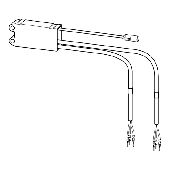
  • Page 8: Montage

    Borne de la Borne dans la Numérotation des boîte de vanne à 3 conducteurs au niveau connexion voies de l’interrupteur de puissance 1 ( )   Montage Raccorder la fiche de l’interrupteur de puissance au niveau de la sortie d’un actionneur programmé...
  • Page 9: Spiegazione Dei Simboli

    Montaggio......... . . 11 Abbreviazioni e unità EA-Nr. Codice articolo europeo FAR-Best.-Nr. Numero d'ordine Franke-Aquarotter Fattore di conversione 1 mm = 0,03937 pollici 1 pollice = 25,4 mm Tutte le quote nelle grafiche sono espresse in millimetri.
  • Page 10: Garanzia

    ☞ Informazioni utili per l’uso ottimale del prodotto. Garanzia La garanzia viene accordata conformemente alle nostre condizioni generali di vendita e consegna. Utilizzare esclusivamente pezzi di ricambio originali! Avvertenze importanti • Montaggio, messa in esercizio e manutenzione solo da parte di un tecnico specia- lizzato secondo le presenti istruzioni, nel rispetto delle prescrizioni di legge e delle regole riconosciute della tecnica.
  • Page 11: Montaggio

    Morsetto della Morsetto Numerazione dei fili scatola di nella valvola sull'interruttore di derivazione a 3 vie potenza 1 ( )   Montaggio Connettere la spina dell’interruttore di potenza ad un’uscita per attuatore specificata- mente programmata di un modulo elettronico. Allacciare le connessioni attuatore dell’interruttore di potenza conformemente all’abbinamento predefinito sull’autoadesivo.
  • Page 12: Verklaring Van De Symbolen

    Montage ..........14 Afkortingen en eenheden EA-Nr. Europees artikelnummer FAR-Best.-Nr. Franke Aquarotter-bestelnummer Omrekening 1 mm = 0,03937 inch 1 inch = 25,4 mm Alle lengtegegevens in tekeningen zijn in mm aangegeven.
  • Page 13: Garantie

    Het niet in acht nemen van de instructie kan storingen in de werking van het product veroorzaken. ☞ Nuttige informatie voor een optimale behandeling van het product. Garantie Met betrekking tot aansprakelijkheid gelden de algemene leverings- en handelsvoor- waarden. Uitsluitend originele reserveonderdelen gebruiken! Belangrijke aanwijzingen •...
  • Page 14: Montage

    Klem van Klem in Adernummers bij aftakdoos drieweg- vermogensschakelaar ventiel 1 ( )   Montage Stekker van de vermogensschakelaar op een overeenkomstig geprogrammeerde actuatoruitgang van een elektronicamodule aansluiten. Actuatoraansluitingen van de vermogensschakelaar in overeenstemming met de voorgeschreven indeling op de sticker aansluiten. ☞...
  • Page 15: Legenda

    Montaż..........17 Skróty i jednostki EA-Nr. Europejski numer artykułu FAR-Best.-Nr. Numer zamówienia Franke Aquarotter Przeliczanie jednostek 1 mm = 0,03937 cala 1 cal = 25,4 mm Wszystkie długości na rysunkach podano w mm.
  • Page 16: Gwarancja

    Gwarancja Zakres i rozdział odpowiedzialności wynika z ogólnych warunków handlowych. Używać wyłącznie oryginalnych części zamiennych! Ważne uwagi • Montaż, uruchamianie i konserwacja muszą być przeprowadzane przez specjalistę zgodnie z dostarczoną instrukcją, regulacjami prawnymi i ogólnie przyjętymi normami technicznymi. • Należy przestrzegać technicznych warunków podłączenia lokalnych zakładów wodociągowych i energetycznych.
  • Page 17: Montaż

    Zacisk puszki Zacisk w Numeracja żył w rozgałęźnej zaworze wyłączniku mocy 3 drożnym  1 ( )  8. Montaż Przyłączyć wtyk wyłącznika mocy do odpowiednio zaprogramowanego wyjścia elementu wykonawczego modułu elektronicznego. 8.2 Przyłączyć przyłącza elementu wykonawczego wyłącznika mocy zgodnie z oznaczeniami na naklejce.
  • Page 18 Notizen...
  • Page 19 Notizen...
  • Page 20 SARL BFIX Franke Caucasus Ltd. Franke Mutfak ve Banyo Sistemleri San. ve Résidence Chaabani 7, Agladze Street Tic. A.S Gebze Organize Sanayi Bölgesi Val d‘Hydra part N°06-C Hydra 08 Tbilisi, 0154 / Georgia DZ-16035 HYDRA-ALGER / Algeria t: +995 (0)32 2351672 Tembelova Alanı...

Ce manuel est également adapté pour:

76 12982 082795

Table des Matières