Masterflex L/S 7523-60 Notice D'utilisation
Table des Matières
Les langues disponibles
Les langues disponibles
Liens rapides
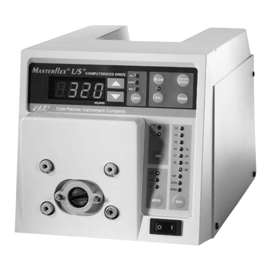
7523 and 7550 Console Drive
77301-23 Wall Mount Controller with 77301-21 Pump Drive and
77301-22 Benchtop Controller
Cole-Parmer
1-800-MASTERFLEX (627-8373) (U.S. and Canada only) • 11 (847) 549-7600 (Outside U.S.)
(847) 549-7600 (Local) • www.masterflex.com • techinfo@coleparmer.com
Thermo Fisher Scientific
1-800-637-3739 (U.S. and Canada only) • 11 (847) 381-7050 (Outside U.S.)
(847) 381-7050 (Local) • www.thermo.com • bar.barnant@thermofisher.com
®
OPERATING MANUAL:
PUMP DRIVES
NOTICE D'UTILISATION :
ENTRAÎNEMENTS DE
POMPES
BEDIENUNGSANLEITUNG:
PUMPENANTRIEBE
MANUAL DE OPERACIÓN:
PROPULSORES DE
BOMBAS
MANUALE DI ISTRUZIONI:
AZIONAMENTI
MANUAL DE OPERAÇÃO:
ACIONADORES DE
BOMBA
Model Nos.
Modèles nº
Modellnummern
Números de modelo
Modelli nº
Modelos N°
®
7523-60
7523-70
7550-30
7550-50
77301-20
77301-30
A-1299-0996
Edition 05
Chapitres
Table des Matières
Dépannage

Manuels Connexes pour Masterflex L/S 7523-60


Sommaire des Matières pour Masterflex L/S 7523-60
-
Page 2: Entraînements De Pompes-Modèles Nº Type
® ® PUMP DRIVES—MODEL NOS. TYPE SYSTEM PUMP DRIVES CONTROLLER Benchtop Modular 77301-20 77301-21 77301-22 NEMA Modular 77301-30 77301-21 77301-23 Std. Console, 600 rpm 7523-60 — — Std. Console, 100 rpm 7523-70 — — Console w/SIO, 600 rpm 7550-30 — —... -
Page 19: Mesures De Sécurité
TABLE DES MATIÈRES Intitulé Page MESURES DE SÉCURITÉ ..............15 INTRODUCTION . -
Page 20: Introduction
® ® pour permettre d’obtenir des débits allant de 0,10 à 3400 ml/mn. Il est possible de monter jusqu'à 2 (600 tr/mn) ou 4 (100 tr/mn) têtes de pompe MASTERFLEX ® ® et toutes les têtes de pompe compatibles MASTERFLEX. -
Page 21: Configuration Et Fonctionnement De L'entraînement
à la mise hors tension. ÉTALONNAGE Utiliser uniquement des tubes MASTERFLEX extrudés avec précision avec les pompes MASTERFLEX pour garantir des performances optimales. L’utilisation d’autres tubes peut annuler les garanties applicables. 1. Sélectionner le diamètre de tubes et le débit corrects. -
Page 22: Distribution/Répétition
DISTRIBUTION/RÉPÉTITION Un premier appui sur la touche DISP (distribution) provoque l’affichage du dernier volume de distribution saisi. Le témoin « mL » s’allume et clignote. Les touches fléchées vers le haut et vers le bas (▲, ▼) servent à modifier le volume distribué... - Page 23 5. Pour régler l’échelle de tension ou d’intensité pour une plage autre que de zéro au maximum, appuyer sur la touche MODE et la maintenir enfoncée tout enappuyant sur la touche FLOW. L’indication « LO » (Minimum) s’affiche pendant 2 secondes, puis un débit apparaît. Appuyer sur les touches fléchées VERS LE HAUT/BAS (▲, ▼) pour sélectionner le niveau de réglage minimum.
-
Page 24: Dépannage Et Entretien
Configuration des broches de prise DB-15 avec schéma de câblage A. MARCHE/ARRÊT B. SENS HORAIRE/ANTIHORAIRE C. SORTIE 0-20 mA ; 4-20 mA D. ENTRÉE 0-20 mA ; 4-20 mA E. ENTRÉE 0-10 V F. SORTIE 0-10 V G. SORTIE COMPTE-TOURS H. -
Page 25: Dépannage
PANNEAU ARRIÈRE - 7523-60, -70 A. PRISE EXTÉRIEURE B. MODULE D'ALIMENTATION IEC 320 C. FUSIBLE T3.15 A ATTENTION : ne pas substituer un autre. PANNEAUX ARRIÈRE A. PRISE EXTÉRIEURE D. FUSIBLE T3.15 A B. PRISE DE MOTEUR ATTENTION : ne pas substituer un autre. C. -
Page 26: Dépannage (Suite)
Dépannage (suite) SYMPTÔME CAUSE SOLUTION B. (suite) Le moteur ne tourne pas B2. Le sélecteur de MODE n’est pas 1. Vérifier que le sélecteur de MODE mais l’affichage s’allume. dans la position correcte. est en position « INT » pour commande à... -
Page 27: Nettoyage
Nettoyage Utiliser des détergents peu agressifs lors du nettoyage du boîtier. Ne jamais le plonger dans du liquide. Pièces de rechange et accessoires Description Numéro de pièce Fusible-T3.15 A 77500-25 Kit d'entretien de pignon (600 tr/mn - console) 07553-06 Kit d'entretien de pignon (600 tr/mn - modulaire) 77300-01 Pignon seul (600 tr/mn) 07553-09... - Page 28 Entrées à distance : Tous modèles ARRÊT/MARCHE, SENS HORAIRE/ANTIHORAIRE, AMORÇAGE (fermeture des contacts) Tous modèles Tension à l'entrée (0-10 V c.c. à 10 kΩ) Intensité à l'entrée (0-20 ou 4-20 mA à 250 Ω) Tous modèles 7550-30, -50 RS-232C 7550-30, -50 ENTRÉE AUX.
-
Page 29: Garantie
GARANTIE Utiliser uniquement des tubes MASTERFLEX extrudés avec précision avec les pompes MASTERFLEX pour garantir des performances optimales. L’utilisation d’autres tubes peut annuler les garanties applicables. Nous garantissons que ce produit est conforme aux descriptifs. Si une réparation ou un réglage s’avère nécessaire durant la période de garantie, le problème sera corrigé... - Page 74 ....................................70 ......................................71 ................................... 71 ....................................72 ................................72 ..............................72 OTH(ER) ..................72 ....................................73 .................................. 73 ................................73 .............................. 73 ............................... 75 ..................................75 ....................................76 ......................................78 .................................. 78 ....................................... 78 ........................................ 80 ....................................80 ....................................... 80 PWM BLDC ®...
- Page 75 PWM BLDC MASTERFLEX L/S ® 0.10 3400 (600 rpm) (100 rpm) MASTERFLEX L/S ® MASTERFLEX 7523 7550 77301 — — C. DISP ( ) — D. FLOW ( — E. CAL ( — F. STOP/START — G. PRIME — H. DIR ( ) —...
- Page 76 1. 77301 SIZE 5. MODE (INT, mA, V) 6. DIRection PRIME 8. FLOW 9. STOP/START STOP/START _ _ _ STOP/START PRIME MASTERFLEX MASTERFLEX 2. CAL 3. STOP/START 6. SIZE OTH(ER FLOW 3. SIZE...
- Page 77 DISP VOLUME UP/DOWN STOP/START UP ( ) DOWN DISP STOP/START DISP COPY STOP/START DISP COPY STOP/START 9999 STOP/START STOP/START DISP UP/DOWN 9999 STOP/START STOP/START STOP/START STOP/START DISP FLOW _ _ _ FLOW PRIME (0 - 20 mA, 4 - 20 mA, 0 - 10V DC) STOP/START;...
- Page 78 FLOW MODE FLOW 77300-32...
- Page 79 DB-15 STOP A. START B. CW 0-20mA; 4-20mA 0-20mA; 4-20mA 0-10V 0-10V H. PRIME N.O. N.C. 7523 7550 77301-22 4. AC A. 6-600 RPM 07553-06 77300-01 C. 1-100 RPM 07553-08 - 7550-30, -50 -RS-232C -RS-232C C. AUX 1 ; AUX 2 , AUX IEC 320 T3.15A...
- Page 80 - 7523-60, - 70 IEC 320 T3.15A T3.15A IEC 320 77301-23 77301-22 MODE STOP START...
- Page 81 B2. MODE MODE mA V ERROR “Err 2” “Err 3” “Err 5” “Err 12” “Err 7” “Err 10” “Err 11” 2. AC 3. AC “Err 14” ERROR ERROR...
- Page 82 -T3.15A 77500-25 (600 rpm - 07553-06 (600 rpm - 77300-01 (600 rpm) 07553-09 (100 rpm) 07553-08 w/ DB-15 07595-42 DB-15 07595-52 DB-15 07595-60 (NEMA)* 07592-83 (NEMA)* 07595-43 , 7.62 (NEMA)* 77300-32 * (77301-30 7523-60, 7550-30, 77301-20, -30 10 - 600 r/min 7523-70, 7550-50 1.6 - 100 r/min 7523-60, 7550-30, 77301-20, -30...
- Page 83 (0 - 10V DC @ 10 kΩ) (0 - 20 mA 4–20 mA @ 250 Ω) 7550-30, -50 RS-232C 7550-30, -50 7523-60, -70, 7550-30, -50 292 x 196 x 182 mm 77301-22 248 x 233 x 129 mm 77301-23 229 x 279 x 114 mm 77301-21 226 x 97 x 120 mm 7523-60, -70, 7550-30, -50...
- Page 85 ......................................81 ......................................... 82 ....................................82 ..................................... 83 ..................................83 ......................................... 83 “OTH(ER)” ..........................83 ......................................84 ....................................84 ......................................... 84 ....................................84 ..................................... 86 ....................................86 ......................................87 ......................................89 ....................................89 ......................................89 ......................................... 91 ......................................91 ......................................91 ®...
- Page 86 ® ® MASTERFLEX 0.10 3400 mL/min ® ® (600 rpm) 4 (100 rpm) MASTERFLEX MASTERFLEX (rear of unit) 77301 7523 7550 C. DISP D. FLOW E. CAL F. STOP/START G. PRIME H. DIR I. MODE J. SIZE K. POWER SWITCH...
- Page 87 77301 " " INT, mA, V PRIME CALibrate FLOW UP/DOWN STOP/START STOP/START STOP/START PRIME "ON" "OFF" "ON" MASTERFLEX MASTERFLEX STOP/START SIZE “OTH(ER)” FLOW SIZE...
- Page 88 DISP "mL" UP/DOWN STOP/START UP ( ) DOWN ( ) DISP STOP/START DISP COPY STOP/START DISP COPY STOP/START 9999 STOP/START STOP/START DISP UP/DOWN 1~9999 STOP/START STOP/START STOP/START STOP/START DISP FLOW 5 FLOW PRIME 0-20 mA 4-20 mA 0-10V DC STOP/START; CW/CCW; PRIME DB-15 MODE MODE...
- Page 89 MODE FLOW “LO” FLOW "HI" 77300-32...
- Page 90 DB-15 0-20mA; 4-20mA 0-20mA; 4-20mA 0-10V 0-10V N.O. N.C. 7523, 7550 77301-22 A. 6-600 RPM 07553-06 77300-01 C. 1-100 RPM 07553-08 – 7550-30, -50 -RS-232C -RS-232C - D. IEC 320 E. T3.15A...
- Page 91 – 7523-60, -70 B. IEC 320 C. T3.15A D. T3.15A C. IEC 320 — 77301-23 77301-22 MODE STOP/START...
- Page 92 B2. MODE MODE MODE MODE “Err 2” “Err 3” “Err 5” “Err 12” “Err 7” “Err 10” “Err 11” “Err 14”...
- Page 93 T3.15A 77500-25 (600 rpm - 07553-06 (600 rpm - 77300-01 (600 rpm) 07553-09 (100 rpm) 07553-08 w/ DB-15 07595-42 DB-15 07595-52 DB-15 07595-60 (NEMA)* 07592-83 (NEMA)* 07595-43 7.62m (NEMA)* 77300-32 77301-30 7523-60, 7550-30, 77301-20, -30 600 r/min 7523-70, 7550-50 100 r/min 7523-60, 7550-30, 77301-20, -30 13 kg•cm 7523-70, 7550-50...
- Page 94 (0–10V DC @ 10 kΩ) (0–20 mA or 4–20 mA @ 250 Ω) 7550-30, -50 RS-232C 7550-30, -50 7523-60, -70, 7550-30, -50 292 196 182 mm 77301-22 248 233 129 mm 77301-23 229 279 114 mm 77301-21 226 97 120 mm 7523-60, -70, 7550-30, -50 6.8 kg 77301-22...