L-Acoustics 115XT HiQ Manuel Utilisateur
Retour de scène coaxial
Masquer les pouces
Voir aussi pour 115XT HiQ:
- Manuel d'utilisation (42 pages) ,
- Manuel utilisateur (72 pages) ,
- Mode d'emploi (61 pages)

Manuels Connexes pour L-Acoustics 115XT HiQ


Sommaire des Matières pour L-Acoustics 115XT HiQ
- Page 1 115XT HiQ COAXIAL STAGE MONITOR 115XT HiQ RETOUR DE SCENE COAXIAL VERSION 1 USER MANUAL MANUEL UTILISATEUR w w w . l - a c o u s t i c s . c o m...
- Page 2 w w w . l - a c o u s t i c s . c o m...
-
Page 3: Safety Warnings
1. Read this manual 2. Heed all safety warnings 3. Follow all instructions 4. The user should never incorporate equipment or accessories not approved by L-ACOUSTICS Sound Levels Sound systems are capable of producing high Sound Pressure Levels that can be dangerous and potentially cause hearing damage especially when exposed to them over a long period of time. -
Page 4: 115Xt Hiq Coaxial Stage Monitor
115XT HiQ COAXIAL STAGE MONITOR User Manual VERSION 1 Heat Do not operate the product near any heat source, such as radiators or other devices. CAUTION Water and moisture Even if the product is weather-resistant, it can not be exposed to moisture directly for a long period of time (rain, sea spray, shower, steam), nor put in direct contact or partially immersed in water. -
Page 5: Ec Declaration Of Conformity
91462 Marcoussis Cedex France State that the following products: Acoustic loudspeaker, 8XT Acoustic loudspeaker, 12XT Acoustic loudspeaker, 115XT HiQ Are in conformity with the provisions of: Machinery Directive 98/37/CE Low Voltage Directive 73/23/CE Applied rules and standards: EN ISO 12100-1: 2004... -
Page 6: Table Des Matières
EC declaration of conformity ..........................3 CONTENTS INTRODUCTION Welcome to L-ACOUSTICS ........................... 5 Unpacking................................5 XT COAXIAL RANGE 115XT HiQ COAXIAL STAGE MONITOR INSTALLATION Rigging material................................ 9 Connecting speakers ............................... 9 OPERATION 115XT HiQ system configuration.......................... 11 “FULL RANGE” mode ............................11 7.2.1... -
Page 7: Introduction
If the product requires repair or if information upon warranty is needed, please contact an approved L-ACOUSTICS distributor. In order to obtain the address of the nearest distributor go to the L-ACOUSTICS internet website @ www.l-acoustics.com. -
Page 8: Xt Coaxial Range
® SB118 subwoofer. The system solution developed by L-ACOUSTICS for the XT range comprises the elements needed to fully take advantage of the possible configurations and optimize the system. The main components of the system are: Passive compact coaxial enclosure... - Page 9 The XT range components are compatible with standard L-ACOUSTICS accessories. These accessories include the loudspeaker cables SP.7, SP10, and SP25 with respective lengths of 0.7m (2.3ft), 10m (32.8ft), and 25m (82ft). Each cable is 4 conductor cable with 4mm conductor cross-section (13 SWG, 11 AWG) and features two NEUTRIK ®...
- Page 10 Figure 2: 115XT HiQ enclosure with rigging components The wedge-shaped cabinet design makes the 115XT HiQ perfectly suited to short or long throw monitoring use with two fixed angle settings of either 30˚ or 60° with regard to the vertical. The cabinet also features two pole sockets to ®...
-
Page 11: Installation
LA4. Each of the LA4 amplification channels 1 and 3 can drive one or two 115XT HiQ enclosures in parallel. The channel assignment varies upon the preset selected by the user for a given application. For more details please refer to the “LA4’’ user manual, also available on the L-ACOUSTICS internet website @ www.l-acoustics.com. - Page 12 Length for one 115XT HiQ / 8 ohms Length for two 115XT HiQ / 4 ohms According to the calculation in Table 1 one SP25 cable (4mm², 25m) can be used to power two 115XT HiQ in parallel (4ohm load) with a damping factor still greater than 20.
-
Page 13: Operation
7.2.1 Connecting to the LA4 The first two 115XT HiQ enclosures are connected to output channels 1 and 3 of the LA4 controller. The additional cabinets are grouped in pairs in parallel with the first ones. Therefore a single LA4 amplified controller can drive up to four 115XT HiQ enclosures (Figure 4). -
Page 14: Hiq_Fr], [Hiq _Fi], And [Hiq _Mo] Presets
VERSION 1 OUT 1 (in A) OUT 3 (in B) Figure 4: Four 115XT HiQ enclosures connected to an LA4 controller 7.2.2 [HIQ_FR], [HIQ _FI], and [HIQ _MO] presets The [HIQ_FR] preset features a low and high frequency shelving equalization. -
Page 15: High Pass" Mode
“HIGH PASS” mode In the ‘‘HIGH PASS’’ mode the 115XT HiQ enclosures are 100 Hz high-pass filtered to allow for coupling with the dedicated complimentary SB118 subwoofers. The bandwidth of the system is extended down to 32 Hz. The recommended ratio is one SB118 for one 115XT HiQ. -
Page 16: Hiq_Fr_100], [Hiq_Fi_100], And [Hiq_Mo_100] Presets
Delay Polarity IN A Input signal A IN_A IN B Input signal B IN_B OUT 1 115XT HiQ enclosure LF_A OUT 2 HF_A 115XT HiQ enclosure OUT 3 LF_B OUT 4 HF_B * IN: input signal, A: channel A, B: channel B, LF: LF transducer, HF: HF transducer HiQ_UM_ML_1 w w w . -
Page 17: Care And Maintenance
However, in order to ensure safety and product performance, it is essential to proceed to a frequent inspection of the 115XT HiQ cabinet and its internal components. The check frequency varies upon the conditions of system use and comprises three steps (see section 8.2). -
Page 18: Specifications
50 - 20k Hz ([HIQ_FR] preset) SPL max levels ‘‘FILL’’ preset 126,5 dB continuous 132,5 dB peak (1 x 115XT HiQ, [HIQ_FI] preset) ‘‘MONITOR’’ preset 129,5 dB continuous 135,5 dB peak (1x115XT HiQ, [HIQ_MO] preset) Nominal directivity (-6dB) 50° (±10°) axi-symmetric Transducers 1 x 15’’... - Page 19 w w w . l - a c o u s t i c s . c o m...
-
Page 20: Déclarations De Sécurité
Lire le présent manuel Suivre les consignes de sécurité Suivre les instructions N’utiliser en aucun cas des équipements ou accessoires non approuvés par L-ACOUSTICS Niveaux sonores Les systèmes de sonorisation sont capables de délivrer un niveau sonore (SPL) nuisible à la santé... - Page 21 115XT HiQ RETOUR DE SCENE COAXIAL Manuel Utilisateur VERSION 1 Chaleur Ne pas utiliser le produit à proximité d’une source de chaleur telle qu’un radiateur ou autre. CAUTION Eau et humidité Bien que peu sensible à l’humidité, le produit ne peut être exposé de manière durable à des projections d’eau (pluie, embruns, douches, vaporisation) ni être au contact de l’eau ou partiellement...
-
Page 22: Déclaration De Conformité Ce
91462 Marcoussis Cedex France Déclare que les produits suivants : Enceinte acoustique, 8XT Enceinte acoustique, 12XT Enceinte acoustique, 115XT HiQ Sont conformes aux dispositions de : Directive Machine 98/37/CE Directive Basse tension 73/23/CE Règles et standards appliqués : EN ISO 12100-1 : 2004 EN60065 Fait à... - Page 23 ENCEINTE COAXIALE 115XT HiQ INSTALLATION Accrochage et posage.............................. 9 Connexion des enceintes............................9 EXPLOITATION Configuration d’un système 115XT HiQ....................... 11 Le mode “LARGE BANDE” ..........................11 7.2.1 Raccordement au LA4..........................11 7.2.2 Les presets [HIQ_FR], [HIQ _FI], et [HIQ _MO].................. 12 Le mode “PASSE-HAUT”............................
-
Page 24: Introduction
Il est nécessaire de lire attentivement ce manuel pour se familiariser avec les procédures. En raison de l’évolution constante des techniques et des normes, L-ACOUSTICS se réserve le droit de modifier sans préavis les caractéristiques des produits et les informations contenues dans ce manuel. Merci de se référer au site internet www.l-acoustics.com... -
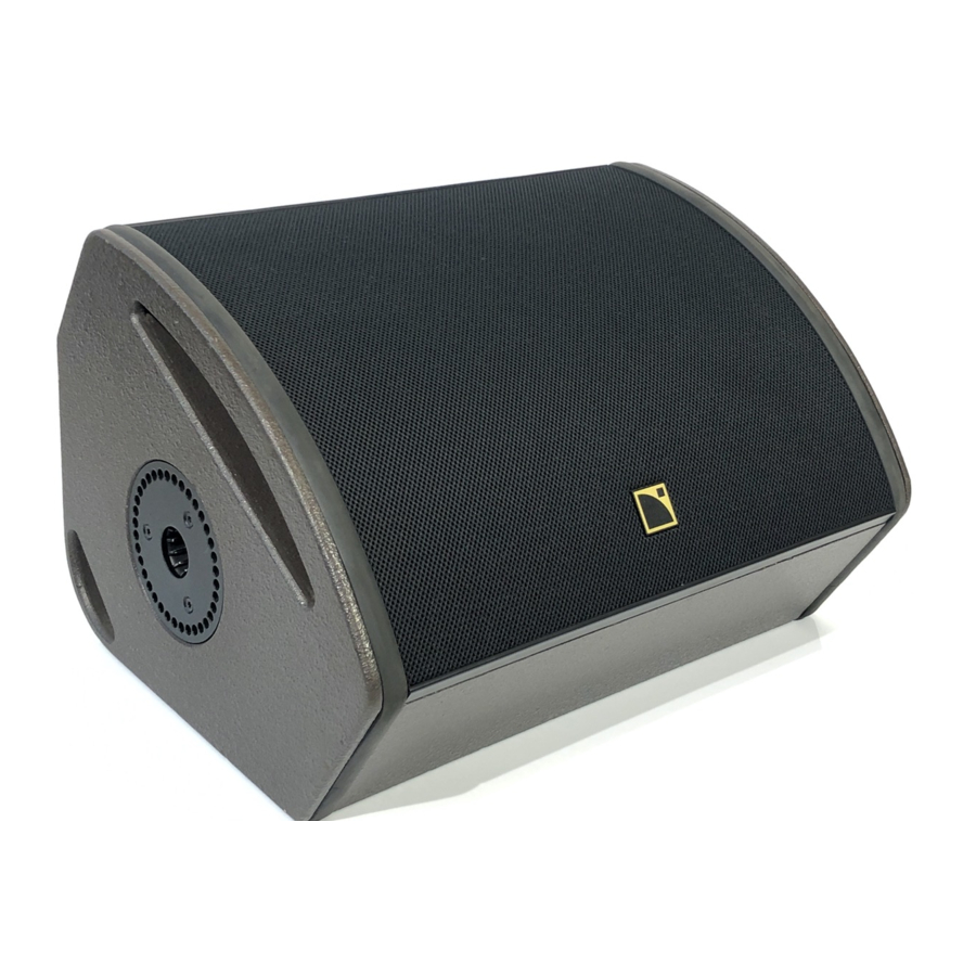
Page 25: Gamme Coaxiale Xt
115XT HiQ constitue l’élément de référence de la Gamme Coaxiale XT. Conçue pour les applications de retour de scène ou de façade distribuée, l’enceinte 115XT HiQ opère en mode actif 2 voies sur la bande de fréquences 50 - 20k Hz. La réponse en fréquence peut être étendue à 32 Hz avec le renfort sub-grave recommandé... - Page 26 La gamme XT peut être complétée par un ensemble d’accessoires au standard L-ACOUSTICS. Parmi ces accessoires figurent les câbles haut-parleurs SP.7, SP10, et SP25 de longueurs respectives 0,7m (2.3ft), 10m (32.8ft), et 25m (82ft). Ces câbles comportent 4 conducteurs de section 4mm...
-
Page 27: Enceinte Coaxiale 115Xt Hiq
étriers L-ACOUSTICS ® ETR15 ou XTLIFTBAR vendus séparément. L’enceinte 115XT HiQ est fabriquée en multipli de bouleau baltique de premier choix, aux propriétés mécaniques et acoustiques remarquables. HiQ_UM_ML_1 w w w . l - a c o u s t i c s . c o m... -
Page 28: Installation
L’enceinte 115XT HiQ est pilotée et amplifiée par le contrôleur amplifié dédié L-ACOUSTICS LA4. Les canaux d’amplification 1 et 3 du LA4 peuvent alimenter chacun une ou deux enceintes 115XT HiQ en parallèle. L’affectation des canaux dépend du preset sélectionné par l’utilisateur pour une application particulière. Pour plus de détail, se référer au ‘‘Manuel Utilisateur LA4’’, téléchargeable du site internet www.l-acoustics.com. - Page 29 Longueur pour 1 HiQ / 8 ohms Longueur pour 2 HiQ / 4 ohms Selon le Tableau 1 un câble SP25 (4mm², 25m) peut alimenter 2 enceintes 115XT HiQ en parallèle (impédance 4 ohms) avec un facteur d’amortissement supérieur à 20.
-
Page 30: Exploitation
Raccordement au LA4 Les deux premières enceintes 115XT HiQ sont raccordées chacune aux sorties 1 et 3 du contrôleur amplifié LA4. Les enceintes suivantes sont associées par paires en parallèle avec les premières. Un seul contrôleur amplifié LA4 peut ainsi supporter jusqu’à... -
Page 31: Les Presets [Hiq_Fr], [Hiq _Fi], Et [Hiq
RETOUR DE SCENE COAXIAL Manuel Utilisateur VERSION 1 Note : Le système est optimisé pour un multiple de 2 enceintes 115XT HiQ. OUT 1 (in A) OUT 3 (in B) Figure 4 : 4 enceintes 115XT HiQ raccordées au contrôleur amplifié LA4 7.2.2... -
Page 32: Le Mode "Passe-Haut
Le mode “PASSE-HAUT” Dans le mode ‘‘PASSE-HAUT’’ les enceintes 115XT HiQ sont utilisées avec un filtre passe-haut à 100 Hz pour autoriser le couplage avec les renforts sub-graves dédiés SB118 et étendre la bande passante du système à 32 Hz. Le ratio recommandé... -
Page 33: Les Presets [Hiq_Fr_100], [Hiq _Fi_100], Et [Hiq
Délai Polarité IN A Signal d’entrée A IN_A IN B Signal d’entrée B IN_B OUT 1 Enceinte 115XT HiQ LF_A OUT 2 HF_A OUT 3 Enceinte 115XT HiQ LF_B OUT 4 HF_B * IN : signal d’entrée, A : canal A, B : canal B, LF : haut-parleur de grave, HF : moteur d’aigu HiQ_UM_ML_1 w w w . -
Page 34: Entretien Et Maintenance
® 115XT HiQ est un produit technique conçu pour des exploitations intenses et variées, en intérieur ou en extérieur. Pour répondre à de telles exigences L-ACOUSTICS a doté l’enceinte 115XT HiQ de composants de grande fiabilité et durabilité : •... -
Page 35: Spécifications Techniques
50 - 20k Hz (preset [HIQ_FR]) Niveau SPL maximal Preset ‘‘FILL’’ 126,5 dB continu 132,5 dB crête (1 x 115XT HiQ, preset [HIQ_FI]) Preset ‘‘MONITOR’’ 129,5 dB continu 135,5 dB crête (1x115XT HiQ, preset [HIQ_MO]) Directivité nominale (-6dB) Axisymétrique 50° (±10°) - Page 36 Document reference: HiQ _UM_ML_1 _________________ © Copyright 2007 by L-ACOUSTICS Parc de la Fontaine de Jouvence, 91462 Marcoussis cedex, France _________________ Distribution date: September 18, 2007 w w w . l - a c o u s t i c s . c o m...
- Page 37 COAXIAL RANGE/ GAMME COAXIALE SELF-POWERED COAXIAL RANGE/ GAMME COAXIALE AMPLIFIEE VERSION 1 USER MANUAL MANUEL UTILISATEUR w w w . l - a c o u s t i c s . c o m...
- Page 38 w w w . l - a c o u s t i c s . c o m...
- Page 39 2. Heed all safety warnings 3. Follow all instructions 4. The user should never incorporate equipment or accessories not approved by L-ACOUSTICS System parts and rigging inspection All system components must be inspected before use, in order to detect any possible defects.
- Page 40 Local regulations Some countries require higher Ultimate Strength Safety Factors and specific rigging approvals: it is the user responsibility to ensure that any overhead suspension of L-ACOUSTICS systems has been made in accordance with all applicable local regulations. As a general rule, L-ACOUSTICS recommends the use of safety steel at all times.
- Page 41 EC declaration of conformity L-ACOUSTICS 13 rue Levacher Cintrat Parc de la Fontaine de Jouvence 91462 Marcoussis Cedex France State that the following products: Mounting accessory, ETR8-2 Mounting accessory, ETR12 Mounting accessory, ETR15 Mounting accessory, ETR15P Rigging accessory, XTLIFTBAR Are in conformity with the provisions of:...
- Page 42 Rigging the 8XT or 108P enclosure with the ETR8-2 ................... 12 6.1.1 Assembling ............................. 12 6.1.2 Disassembling............................13 Rigging the 12XT or 112P (resp.115XT HiQ) enclosure with the ETR12 (resp. ETR15)........14 6.2.1 Assembling ............................. 14 6.2.2 Disassembling............................15 Rigging the SB15P enclosure with the ETR15P ..................... 16 6.3.1...
-
Page 43: Introduction
If the product requires repair or if information upon warranty is needed, please contact an approved L-ACOUSTICS distributor. In order to obtain the address of the nearest distributor go to the L-ACOUSTICS internet website @ www.l-acoustics.com. -
Page 44: Xt And P Coaxial Ranges
XTLIFTBAR rigging accessory is dedicated for flying the 12XT and 115XT HiQ enclosures. The system solution developed by L-ACOUSTICS for the XT range consists of the elements needed to fully take advantage of the possible configurations and optimize the system. The main components of the system are:... - Page 45 XTLIFTBAR rigging accessory is dedicated for flying the 112P enclosure. The system solution developed by L-ACOUSTICS for the P range consists of the elements needed to fully take advantage of the possible configurations and optimize the system. The main components of the system are:...
-
Page 46: Xt Coaxial Range
It is the sole responsibility of the user to verify that the ETR8-2 is correctly secured to the structure. L-ACOUSTICS recommends securing to a concrete ceiling using expansion anchors designed to support at least 5 times the total load of the system (the weight of the product is indicated on the identification label of each product). -
Page 47: Etr12 And Etr15 Mounting Accessories
® 12XT or 112P (resp. 115XT HiQ) enclosure. It can be either fastened to a wall or suspended from a structure or ceiling (typically for under-balcony applications). It is possible to secure the ETR12 (resp. ETR15) to a structure using three 10mm/0.39in screws (not provided). -
Page 48: Etr15P Mounting Accessory
It is the sole responsibility of the user to verify that the ETR15P is correctly secured to the structure. L-ACOUSTICS recommends securing to a concrete ceiling using expansion anchors designed to support at least 5 times the total load of the system (the weight of the product is indicated on the identification label of each product). -
Page 49: Xtliftbar Rigging Accessory
It is provided with one shackle that can support up to 250kg/551 lb with an Ultimate Strength Safety Factor of 5:1. This shackle allows for flying the 12XT, 112P, or 115XT HiQ enclosures using one rigging point. The XTLIFTBAR can support one 12XT, 112P, or 115XT HiQ at the maximum. -
Page 50: Installation
COAXIAL RANGE - SELF-POWERED COAXIAL RANGE Rigging Procedures VERSION 1 INSTALLATION Rigging the 8XT or 108P enclosure with the ETR8-2 6.1.1 Assembling The ETR8-2 U-bracket is secured to the 8XT or 108P enclosure in the following way: Remove the recessed set screw located on the top face of the enclosure. Note: Put the screw in a safe place. -
Page 51: Disassembling
WARNING L-ACOUSTICS recommends using an additional safety point when rigging enclosures. A safety eye-bolt accessory can be added using the 8mm/0.31in insert located on the rear face of the 8XT enclosure (see Figure 18). -
Page 52: Rigging The 12Xt Or 112P (Resp.115Xt Hiq) Enclosure With The Etr12 (Resp. Etr15)
6.2.1 Assembling The ETR12 (resp. ETR15) U-bracket is secured to the 12XT or 112P (resp. 115XT HiQ) enclosure in the following way: a. Remove the locking pin located on the U-bracket’s pivoting arm. b. Pull on the spring-loaded pin and open the pivoting arm. -
Page 53: Disassembling
Verify that the enclosure is secured to the U-bracket by checking that the locking pin is engaged and cannot move freely. WARNING L-ACOUSTICS recommends using an additional safety point when rigging enclosures. A safety eye-bolt accessory can be added using the 8mm/0.31in insert located on the rear face of the 12XT enclosure (see Figure 18). -
Page 54: Rigging The Sb15P Enclosure With The Etr15P
COAXIAL RANGE - SELF-POWERED COAXIAL RANGE Rigging Procedures VERSION 1 Rigging the SB15P enclosure with the ETR15P 6.3.1 Assembling The ETR15P is secured to the SB15P enclosure in the following way: Remove the recessed set screw located on the bottom face of the enclosure. Note: Put the screw in a safe place. -
Page 55: Disassembling
WARNING L-ACOUSTICS recommends using an additional safety point when rigging enclosures. A safety eye-bolt accessory can be added using the 8mm/0.31in insert located on the rear face of the SB15P enclosure (see Figure 18). -
Page 56: Flying The 12Xt, 112P, Or 115Xt Hiq Enclosure With The Xtliftbar
COAXIAL RANGE - SELF-POWERED COAXIAL RANGE Rigging Procedures VERSION 1 Flying the 12XT, 112P, or 115XT HiQ enclosure with the XTLIFTBAR 6.4.1 Assembling Remove both locking pins. a. Insert the XTLIFTBAR stud into the enclosure’s top pole socket. b. Select the desired angle: in 10° steps for azimuth angle setting (directivity in the horizontal plane), or at the 0°... -
Page 57: Disassembling
Figure 17: XTLIFTBAR with shackle in hole position #4 (-7° site angle) Fly the enclosure by rigging to the shackle. L-ACOUSTICS recommends using an additional safety point when rigging enclosures. A safety eye-bolt accessory can be added using the 8mm/0.31in insert located on the rear face of the 12XT enclosure (see Figure 18). -
Page 58: Rigging The 8Xt Or 12Xt Enclosure With The Omnimount
OMNIMOUNT 120.0 SERIES mounting accessories for the 12XT enclosure. L-ACOUSTICS recommends using an additional safety point when rigging enclosures. A safety eye-bolt accessory can be added using the 8mm/0.31in insert located on the rear face of the enclosure (see Figure 18). -
Page 59: Care And Maintenance
CARE AND MAINTENANCE The components for assembling the XT and P range enclosures are as follows: • Mounting accessories ETR8-2, ETR12, ETR15, and ETR15P • Rigging accessory XTLIFTBAR If components are used in the manner as described in this manual, they will remain fully operational over the life of the enclosure. -
Page 60: Specifications
COAXIAL RANGE - SELF-POWERED COAXIAL RANGE Rigging Procedures VERSION 1 SPECIFICATIONS Reference ETR8-2 Dimensions (W x H x D) 485 x 225 x 50 mm 19.1 x 8.9 x 2 in Weight 1.9 kg 4.2 lb Setup safety limit Maximum of one 8XT or 108P enclosure per ETR8-2 Material black epoxy-coated steel Reference... - Page 61 670 x 345 x 54 mm 26.4 x 13.6 x 2.1 in Weight 5.5 kg 12.1 lb Setup safety limit Maximum of one 115XT HiQ enclosure per ETR15 Material black epoxy-coated steel Reference ETR15P Dimensions (W x H x D) 527 x 415 x 53.5 mm...
- Page 62 Weight 0.55 kg 1.2 lb Setup safety limit Maximum of one 12XT, 112P, or 115XT HiQ enclosure per XTLIFTBAR Material black epoxy-coated steel XTP_RM_ML_1 w w w . l - a c o u s t i c s . c o m...
- Page 63 w w w . l - a c o u s t i c s . c o m...
- Page 64 2. Suivre les consignes de sécurité 3. Suivre les instructions 4. N’utiliser en aucun cas des équipements ou accessoires non approuvés par L-ACOUSTICS Vérification du matériel Tous les éléments d’un système de sonorisation doivent être inspectés avant leur utilisation afin de détecter d’éventuels défauts.
-
Page 65: Procedures D'accrochage
WARNING Limites mécaniques du système Lors du levage ou du posage d’un système L-ACOUSTICS il est de la responsabilité de l’utilisateur de respecter les limites mécaniques décrites dans ce manuel. Toujours se référer à la section ‘‘Mechanical Data’’ du logiciel SOUNDVISION pour vérifier la tenue mécanique de toute configuration. - Page 66 Déclaration de conformité CE L-ACOUSTICS 13 rue Levacher Cintrat Parc de la Fontaine de Jouvence 91462 Marcoussis Cedex France Déclare que les produits suivants : Accessoire d’accrochage, ETR8-2 Accessoire d’accrochage, ETR12 Accessoire d’accrochage, ETR15 Accessoire d’accrochage, ETR15P Accessoire de levage, XTLIFTBAR...
- Page 67 Accrochage d’une enceinte 8XT ou 108P par l’étrier ETR8-2................12 6.1.1 Montage ..............................12 6.1.2 Démontage ............................13 Accrochage d’une enceinte 12XT ou 112P (resp.115XT HiQ) par l’étrier ETR12 (resp. ETR15) ....... 14 6.2.1 Montage ..............................14 6.2.2 Démontage ............................15 Accrochage d’une enceinte SB15P par l’étrier ETR15P ..................
-
Page 68: Introduction
XT et P. Il est nécessaire de lire attentivement ce manuel pour se familiariser avec les procédures. En raison de l’évolution constante des techniques et des normes, L-ACOUSTICS se réserve le droit de modifier sans préavis les caractéristiques des produits et les informations contenues dans ce manuel. Se référer au site internet www.l-acoustics.com... -
Page 69: Gamme Coaxiales Xt Et P
XTLIFTBAR est dédié au levage des enceintes 12XT et 115XT HiQ. La solution système développée par L-ACOUSTICS pour la gamme XT comprend un ensemble d’éléments qui peuvent être associés les uns aux autres pour supporter toutes les configurations possibles. Les principaux éléments du système sont :... -
Page 70: La Gamme Coaxiale Amplifiée P
XTLIFTBAR est dédié au levage de l’enceinte 112P. La solution système développée par L-ACOUSTICS pour la gamme P comprend un ensemble d’éléments qui peuvent être associés les uns aux autres pour supporter toutes les configurations possibles. Les principaux éléments du système sont : 108P Enceinte coaxiale amplifiée... -
Page 71: Accessoires Etr8-2, Etr12, Etr15, Etr15P, Et Xtliftbar
Il est de la responsabilité de l’utilisateur de contrôler que l’étrier ETR8-2 soit correctement fixé au support. L-ACOUSTICS recommande la fixation de l’étrier ETR8-2 dans un plafond ou un mur en béton à l’aide de chevilles à expansion prévues pour supporter au moins 5 fois la charge totale du système (les indications de poids figurent sur les étiquettes d’identification des produits). -
Page 72: Accessoires D'accrochage Etr12 Et Etr15
® L-ACOUSTICS 12XT ou 112P (resp. 115XT HiQ). Il peut être fixé à un mur ou suspendu à une structure ou un plafond (typiquement pour une utilisation sous-balcon). Des perçages sur la barre principale permettent la fixation de l’étrier à l’aide de trois vis de diamètre 10mm/0.39in (non fournies). -
Page 73: Accessoire D'accrochage Etr15P
Il est de la responsabilité de l’utilisateur de contrôler que l’étrier ETR15P soit correctement fixé au support. L-ACOUSTICS recommande la fixation de l’étrier ETR15P dans un plafond ou un mur en béton à l’aide de chevilles à expansion prévues pour supporter au moins 5 fois la charge totale du système (les indications de poids figurent sur les étiquettes d’identification des produits). -
Page 74: Accessoire De Levage Xtliftbar
Il est fourni avec une manille lyre supportant 250kg/551 lb avec un coefficient de sécurité à la rupture de 5:1. Cette manille permet de soulever une enceinte 12XT, 112P, ou 115XT HiQ avec un point de suspension. L’accessoire de levage XTLIFTBAR peut supporter une enceinte 12XT, 112P, ou 115XT HiQ au maximum. -
Page 75: Installation
GAMME COAXIALE GAMME COAXIALE AMPLIFIEE PROCEDURES D’ACCROCHAGE VERSION 1 INSTALLATION Accrochage d’une enceinte 8XT ou 108P par l’étrier ETR8-2 6.1.1 Montage L’étrier ETR8-2 s’enclenche sur une enceinte 8XT ou 108P de la manière suivante : Ôter la vis de réglage située sur la face supérieure de l’enceinte. Note : Mettre la vis en lieu sûr. -
Page 76: Démontage
Pour installer l’enceinte en position verticale, toujours positionner le bras fixe de l’étrier ETR8-2 au- dessous de l’enceinte. WARNING L-ACOUSTICS recommande l'utilisation d’une sécurité supplémentaire à chaque accrochage d’enceinte. Un insert de diamètre 8mm/0.31in est prévu à cet effet sur la face arrière de l’enceinte 8XT pour l’adjonction d’un anneau de levage (voir Figure 18). -
Page 77: Accrochage D'une Enceinte 12Xt Ou 112P (Resp.115Xt Hiq) Par L'étrier Etr12 (Resp. Etr15)
6.2.1 Montage L’étrier ETR12 (resp. ETR15) s’enclenche sur une enceinte 12XT ou 112P (resp. 115XT HiQ) de la manière suivante : 1. a. Ôter la goupille à attache rapide située à l’extrémité du bras articulé de l’étrier. b. Tirer la goupille de sécurité et ouvrir le bras articulé. -
Page 78: Démontage
S’assurer que la goupille à attache rapide est correctement enclenchée en vérifiant qu’elle ne puisse plus translater librement. WARNING L-ACOUSTICS recommande l'utilisation d’une sécurité supplémentaire à chaque accrochage d’enceinte. Un insert de diamètre 8mm/0.31in est prévu à cet effet sur la face arrière de l’enceinte 12XT pour l’adjonction d’un anneau de levage (voir Figure 18). -
Page 79: Accrochage D'une Enceinte Sb15P Par L'étrier Etr15P
GAMME COAXIALE GAMME COAXIALE AMPLIFIEE PROCEDURES D’ACCROCHAGE VERSION 1 Accrochage d’une enceinte SB15P par l’étrier ETR15P 6.3.1 Montage L’étrier ETR15P s’enclenche sur une enceinte SB15P de la manière suivante : Ôter la vis de réglage située sur la face inférieure de l’enceinte. Note : Mettre la vis en lieu sûr. -
Page 80: Démontage
Pour installer l’étrier ETR15P en position verticale, toujours positionner le bras fixe au-dessous de l’enceinte. WARNING L-ACOUSTICS recommande l'utilisation d’une sécurité supplémentaire à chaque accrochage d’enceinte. Un insert de diamètre 8mm/0.31in est prévu à cet effet sur la face arrière de l’enceinte SB15P pour l’adjonction d’un anneau de levage (voir Figure 18). -
Page 81: Levage D'une Enceinte 12Xt, 112P, Ou 115Xt Hiq Par L'accessoire Xtliftbar
GAMME COAXIALE GAMME COAXIALE AMPLIFIEE PROCEDURES D’ACCROCHAGE VERSION 1 Levage d’une enceinte 12XT, 112P, ou 115XT HiQ par l’accessoire XTLIFTBAR 6.4.1 Montage Ôter les deux goupilles à attache rapide. a. Insérer le pion du XTLIFTBAR dans l’embase supérieure de l’enceinte. -
Page 82: Démontage
WARNING Suspendre l’ensemble en accrochant le câble de levage à la manille. L-ACOUSTICS recommande l'utilisation d’une sécurité supplémentaire à chaque accrochage d’enceinte. Un insert de diamètre 8mm/0.31in est prévu à cet effet sur la face arrière de l’enceinte 12XT pour l’adjonction d’un anneau de levage (voir Figure 18). -
Page 83: Accrochage D'une Enceinte 8Xt Ou 12Xt Par Support Omnimount
OMNIMOUNT ® SÉRIE 120.0 pour l’enceinte 12XT. L-ACOUSTICS recommande l'utilisation d’une sécurité supplémentaire à chaque accrochage d’enceinte. Un insert de diamètre 8mm/0.31in est prévu à cet effet sur la face arrière de l’enceinte pour l’adjonction d’un anneau de levage (voir Figure 18). -
Page 84: Entretien Et Maintenance
ENTRETIEN ET MAINTENANCE Les éléments d’accrochage des gammes XT et P sont les suivants : • Accessoires d’accrochage ETR8-2, ETR12, ETR15, et ETR15P • Accessoire de levage XTLIFTBAR S’ils sont utilisés dans le strict respect des procédures décrites dans ce manuel, ces accessoires doivent rester opérationnels pendant la durée de vie de l’enceinte. -
Page 85: Spécifications Techniques
GAMME COAXIALE GAMME COAXIALE AMPLIFIEE PROCEDURES D’ACCROCHAGE VERSION 1 SPÉCIFICATIONS TECHNIQUES Référence ETR8-2 Dimensions (L x H x P) 485 x 225 x 50 mm 19.1 x 8.9 x 2 in Poids 1,9 kg 4.2 lb Limite mécanique du système 1 enceinte 8XT ou 108P au maximum Matériau Acier, revêtement poudre époxy noire... - Page 86 670 x 345 x 54 mm 26.4 x 13.6 x 2.1 in Poids 5,5 kg 12.1 lb Limite mécanique du système 1 enceinte 115XT HiQ au maximum Matériau Acier, revêtement poudre époxy noire Référence ETR15P Dimensions (L x H x P) 527 x 415 x 53,5 mm 20.7 x 16.3 x 2.1 in...
- Page 87 Poids 0,55 kg 1.2 lb Limite mécanique du système 1 enceinte 12XT, 112P, 115XT HiQ au maximum Matériau Acier, revêtement poudre époxy noire XTP_RM_ML_1 w w w . l - a c o u s t i c s . c o m...
- Page 88 Document Reference: XTP_RM_ML_1 _________________ © Copyright 2007 by L-ACOUSTICS Parc de la Fontaine de Jouvence, 91462 Marcoussis cedex, France _________________ Distribution date: September 19, 2007 w w w . l - a c o u s t i c s . c o m...