
Manuels Connexes pour L-Acoustics KIVA COMPACT WST


Sommaire des Matières pour L-Acoustics KIVA COMPACT WST
- Page 1 KIVA ® COMPACT WST ENCLOSURE KIVA ® ENCEINTE WST COMPACTE VERSION 1.2 USER MANUAL MANUEL D’UTILISATION w w w . l - a c o u s t i c s . c o m...
-
Page 21: Déclarations De Sécurité
2. Suivre les consignes de sécurité 3. Suivre les instructions ® 4. N’utiliser en aucun cas des équipements ou accessoires non approuvés par L-ACOUSTICS Niveaux sonores Les systèmes de sonorisation sont capables de délivrer un niveau sonore (SPL) nuisible à la santé humaine. Les niveaux de pression sonore apparemment non critiques peuvent endommager l’audition si la personne y est exposée sur une longue période. - Page 22 KIVA ® ENCEINTE WST COMPACTE Manuel d’utilisation VERSION 1.2 Chaleur Ne pas utiliser le produit à proximité d’une source de chaleur telle qu’un radiateur ou autre. CAUTION Eau et humidité Bien que peu sensible à l’humidité, le produit ne peut être exposé de manière durable à des projections d’eau (pluie, embruns, douches, vaporisation) ni être au contact de l’eau ou partiellement immergé, sous peine de détérioration irréversible de certains des composants exposés.
-
Page 23: Déclaration De Conformité Ce
Déclaration de conformité CE L-ACOUSTICS ® 13 rue Levacher Cintrat Parc de la Fontaine de Jouvence 91462 Marcoussis Cedex France Déclare que le produit suivant : Enceinte acoustique, KIVA Est conforme aux dispositions de : Directive Machine, 98/37/CE Directive Basse Tension, 73/23/CE Règles et standards appliqués :... - Page 24 SOMMAIRE DÉCLARATIONS DE SÉCURITÉ Symboles utilisés..............................1 Consignes de sécurité importantes ......................... 1 Déclaration de conformité CE..........................3 SOMMAIRE INTRODUCTION Bienvenue chez L-ACOUSTICS ® ..........................5 Déballage du produit ............................... 5 SYSTÈME KIVA ENCEINTE KIVA INSTALLATION Posage ou levage du KIVA ............................9 Connexion des enceintes............................
-
Page 25: Introduction
Si le produit nécessite une réparation ou pour tout renseignement sur la garantie, contacter un distributeur agréé. Pour obtenir les coordonnées du distributeur le plus proche consulter le site internet L-ACOUSTICS ®... -
Page 26: Système Kiva
80 Hz à 20 kHz. La réponse en fréquence du système peut être étendue à 50 Hz avec le renfort de grave L-ACOUSTICS ® KILO. L’approche système développée par L-ACOUSTICS pour le KIVA comprend un ensemble d’éléments qui, associés les ® uns aux autres, supportent et optimisent toutes les configurations possibles. Les principaux éléments du système sont :... - Page 27 Chaque configuration devrait être préalablement modélisée et étudiée dans l’application L-ACOUSTICS ® SOUNDVISION dont les prédictions sont calibrées sur les paramètres système fournis par les contrôleurs amplifiés. Plusieurs contrôleurs amplifiés peuvent être interconnectés et pilotés au sein du réseau propriétaire L-ACOUSTICS ® L-NET via l’application L-ACOUSTICS ®...
-
Page 28: Enceinte Kiva
VERSION 1.2 ENCEINTE KIVA ® L’enceinte L-ACOUSTICS KIVA comprend deux haut-parleurs de 6.5’’ montés dans une enceinte bass-reflex pour le registre grave, et un moteur à chambre de compression de diaphragme de 1.5’’ chargé par un guide d’onde DOSC ®... -
Page 29: Installation
KIVA. WARNING Connexion des enceintes L’enceinte KIVA est pilotée et amplifiée par le contrôleur amplifié dédié L-ACOUSTICS ® LA4. Chaque canal d’amplification du LA4 peut alimenter une ou deux enceintes KIVA ou KILO en parallèle. L’affectation des canaux dépend du preset sélectionné... - Page 30 KIVA ® ENCEINTE WST COMPACTE Manuel d’utilisation VERSION 1.2 Figure 3 : Raccordement de deux enceintes KIVA en parallèle au contrôleur amplifié LA4 Pour des raisons de sécurité et de performances, utiliser uniquement des câbles d’enceintes en cuivre totalement isolés. Pour conserver un facteur d’amortissement suffisamment élevé...
-
Page 31: Exploitation
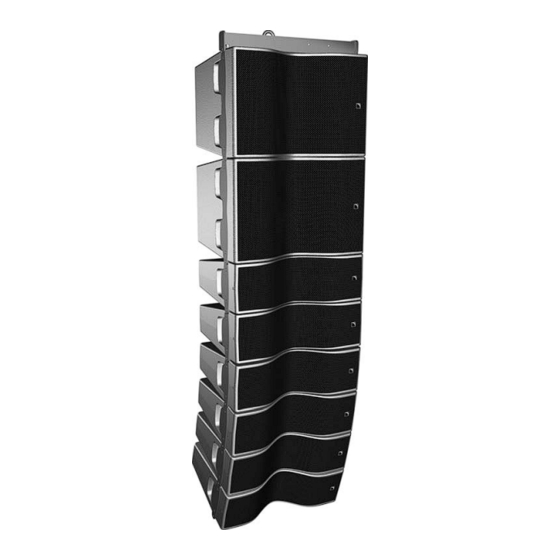
‘‘LARGE BANDE’’, ou en ligne source ‘‘EXTENSION GRAVE’’ en combinaison avec des enceintes KILO. Note : La dernière version de la bibliothèque de presets est fournie par les distributeurs L-ACOUSTICS ® ou est téléchargeable du site www.l-acoustics.com. - Page 32 KIVA ® ENCEINTE WST COMPACTE Manuel d’utilisation VERSION 1.2 OUT 1 OUT 2 OUT 3 OUT 4 Figure 4 : Ligne source de 8 enceintes KIVA en configuration mono OUT 1 (canal A) OUT 3 (canal B) OUT 2 (canal A) OUT 4 (canal B) Figure 5 : 4 paires d’enceintes KIVA en configuration distribuée KIVA_UM_ML_1.2...
-
Page 33: Les Presets [Kiva] Et [Kiva_Fi]
7.2.2 Les presets [KIVA] et [KIVA_FI] Le preset [KIVA] propose un contour spécifique pour l’utilisation en diffusion moyenne et longue portée sur la bande passante 80 Hz-20 kHz. Le preset [KIVA_FI] propose un contour nominalement plat jusqu’à 80 Hz. Dans le menu de l’interface utilisateur du contrôleur amplifié LA4, sélectionner LOAD PRESET puis le preset désiré. Se reporter au document ‘‘LA4 - Manuel d’Utilisation’’... -
Page 34: Le Mode "Extension Grave
à 60 Hz. Ce preset est dédié à l’emploi d’une ligne source KIVA / KILO avec un système sub- ® grave L-ACOUSTICS SB118. La proportion recommandée est 3 KIVA/1 KILO/1 SB118. La bande passante est alors étendue à... - Page 35 Dans le menu de l’interface utilisateur du contrôleur amplifié LA4 sélectionner LOAD PRESET puis le preset désiré. Se reporter au document ‘‘LA4 – Manuel d’Utilisation’’ pour les instructions d’utilisation complémentaires. Les presets sont également accessibles via l’application LA NETWORK MANAGER (se reporter au document ‘‘LA NETWORK MANAGER –...
-
Page 36: Entretien Et Maintenance
® L’enceinte acoustique L-ACOUSTICS KIVA est un produit technique conçu pour des exploitations intenses et variées, en intérieur ou en extérieur. Pour répondre à de telles exigences L-ACOUSTICS ® a doté l’enceinte KIVA de composants de grande fiabilité et durabilité : •... -
Page 37: Remplacement Des Transducteurs
Remplacement des transducteurs Dans les procédures suivantes, serrer chaque vis au couple 5 N.m (45 in.lb IMPORTANT 8.3.1 Haut-parleur LF Si un haut-parleur LF est détérioré il doit être démonté et remplacé en suivant la procédure décrite ci-dessous. Démontage d’un haut-parleur LF 1. -
Page 38: Pièces Détachées Et Outils Recommandés
KIVA ® ENCEINTE WST COMPACTE Manuel d’utilisation VERSION 1.2 Remplacement du moteur HF ou du diaphragme Pour installer un moteur entier : Positionner le nouveau moteur sur la plaque radiateur, l’embase électrique rouge du côté des échancrures de la plaque (si nécessaire, rajouter de la pâte thermique entre la plaque et le moteur). -
Page 39: Spécifications Techniques
Niveau crête mesuré à 1m en champ libre avec un bruit rose (10 dB de facteur de crête) filtré par le preset spécifié. ® Les consignes d’installation sont indiquées dans SOUNDVISION, logiciel d’aide à l’exploitation des produits L-ACOUSTICS KIVA_UM_ML_1.2 w w w . l - a c o u s t i c s . c o m...