Publicité

Les langues disponibles

Les langues disponibles

Liens rapides

Bedienungsanleitung
Instruction manual
Mode d'emploi
Allgemeine Hinweise ............................................2
1.
Sicherheitshinweise ..............................................3
2.
Bestimmungsgemäße Verwendung ......................4
3.
Produktbeschreibung ..........................................5
3.1
Anzeige- und Bedienelemente ........................................5
3.2
Schnittstellen ..................................................................6
3.3
Spannungsversorgung ....................................................6
4.
Inbetriebnahme ....................................................7
5.
Bedienung............................................................8
5.1
Fühler anschließen ..........................................................8
5.2
Gerät ein- / ausschalten ..................................................8
5.3
Displaybeleuchtung ein- / ausschalten ............................8
5.4
Einstellungen vornehmen ................................................9
6.
Messen ..............................................................12
7.
Wartung und Pflege............................................14
8.
Fragen und Antworten........................................15
9.
Technische Daten ..............................................16
10. Zubehör / Ersatzteile ..........................................17
testo 720
Temperatur-Messgerät
Inhalt
de
en
fr

Publicité

Table des Matières
loading

Sommaire des Matières pour TESTO 720

  • Page 1: Table Des Matières

    720 Temperatur-Messgerät Bedienungsanleitung Instruction manual Mode d’emploi Inhalt Allgemeine Hinweise ..........2 Sicherheitshinweise ..........3 Bestimmungsgemäße Verwendung ......4 Produktbeschreibung ..........5 Anzeige- und Bedienelemente ........5 Schnittstellen ..............6 Spannungsversorgung ............6 Inbetriebnahme ............7 Bedienung............8 Fühler anschließen ............8 Gerät ein- / ausschalten ..........8 Displaybeleuchtung ein- / ausschalten ......8 Einstellungen vornehmen ..........9...
  • Page 2: Allgemeine Hinweise

    Allgemeine Hinweise Allgemeine Hinweise Dieses Kapitel gibt wichtige Hinweise zur Nutzung der vor - liegen den Dokumentation. Diese Dokumentation enthält Informationen, die für einen sicheren und effizienten Einsatz des Produkts beachtet werden müssen. Lesen Sie diese Dokumentation aufmerksam durch und machen Sie sich mit der Bedienung des Produkts vertraut, bevor Sie es einsetzen.
  • Page 3: Sicherheitshinweise

    Aus Sicher heits gründen nur Original- Ersatzteile von Testo verwenden. Fachgerecht entsorgen Defekte Akkus / leere Batterien an den dafür vor - gesehenen Sammelstellen abgeben. Produkt nach Ende der Nutzungszeit an Testo senden. Wir sorgen für eine umwelt schonende Entsorgung.
  • Page 4: Bestimmungsgemäße Verwendung

    Setzen Sie das Produkt nur für die Bereiche ein, für die es konzipiert wurde. Im Zweifelsfall bitte bei Testo nachfragen. Das testo 720 ist ein kompaktes Messgerät zur Messung von Temperaturen über steckbare Temperatur fühler. Das Produkt wurde für folgende Aufgaben / Bereiche konzipiert: ·...
  • Page 5: Produktbeschreibung

    3. Produktbeschreibung 5 Produktbeschreibung Dieses Kapitel gibt eine Übersicht über die Komponenten des Produkts und deren Funktionen. 3.1 Anzeige- und Bedienelemente Übersicht ➀ Infrarot-Schnittstelle, Fühlerbuchse ➁ Display ➂ Bedientasten ➃ Batteriefach (Rückseite) ➄ Servicefach (Rückseite) Tastenfunktionen Taste Funktionen Gerät einschalten; Gerät ausschalten (gedrückt halten) Displaybeleuchtung ein-/ ausschalten Messwert halten, Maximal-/ Minimal -...
  • Page 6: Schnittstellen

    Obere Alarmgrenze: leuchtet bei Überschreitung Untere Alarmgrenze: leuchtet bei Unterschreitung 3.2 Schnittstellen Infrarot-Schnittstelle Über die Infrarot-Schnittstelle an der Kopfseite des Geräts können Messdaten an einen Testo-Protokoll drucker gesendet werden. Fühlerbuchse Über die Fühlerbuchse an der Kopfseite des Geräts kann ein steckbarer Messfühler angeschlossen werden.
  • Page 7: Inbetriebnahme

    4. Inbetriebnahme 7 Inbetriebnahme Dieses Kapitel beschreibt die Handlungsschritte, die zur Inbetrieb nahme des Produkts erforderlich sind. ➣ Batterie / Akku einlegen: Batteriefach auf der Rückseite des Gerätes öffnen: Batteriefachdeckel in Pfeilrichtung schieben und abnehmen. Batterie / Akku (9V-Block) einlegen. Polung beachten! Batteriefach schließen: Batteriefachdeckel aufsetzen und gegen die Pfeilrichtung schieben.
  • Page 8: Bedienung

    5. Bedienung Bedienung Dieses Kapitel beschreibt die Handlungsschritte, die beim Einsatz des Produkts häufig ausgeführt werden müssen. 5.1 Fühler anschließen Steckbare Fühler Steckbare Fühler müssen vor dem Einschalten des Mess - geräts angeschlossen werden, damit diese vom Messgerät erkannt werden. Anschlussstecker des Fühlers in die Fühlerbuchse des Messgeräts stecken.
  • Page 9: Einstellungen Vornehmen

    5. Bedienung 9 5.4 Einstellungen vornehmen Konfigurationsmodus öffnen: ✓ Das Gerät ist eingeschaltet und befindet sich in der Mess ansicht. Hold, Max oder Min sind nicht aktiviert. gedrückt halten (ca. 2s) bis die Anzeige im Display wechselt. - Das Gerät befindet sich nun im Konfigurations - modus.
  • Page 10 5. Bedienung Max.- / Min.- Druckfunktion einstellen: ✓ Der Konfigurationsmodus ist geöffnet, MaxMin blinkt. die gewünschte Option wählen und mit bestätigen: · on: Maximal- und Minimalwerte werden beim Drucken von aktuellen oder festgehaltenen Messwerten mit ausgedruckt. · oFF: Maximal- und Minimalwerte werden beim Drucken von aktuellen oder festgehaltenen Messwerten nicht mit aus gedruckt.
  • Page 11 5. Bedienung 11 Reset durchführen: ✓ Der Konfigurationsmodus ist geöffnet, RESET leuchtet. die gewünschte Option wählen und mit bestätigen: · no: Keinen Reset durchführen. · Yes: Einen Reset durchführen. Dabei wird das Gerät auf die Werkseinstellungen zurück gesetzt. Die Einstellung von Datum / Uhrzeit wird nicht zurückgesetzt.
  • Page 12: Messen

    6. Messen Messen Dieses Kapitel beschreibt die Handlungsschritte, die zur Durch führung von Messungen mit dem Produkt erforder - lich sind. ➣ Messung durchführen: ✓ Das Gerät ist eingeschaltet und befindet sich in der Mess ansicht. Fühler positionieren und Messwerte ablesen. Bei eingeschalteter Alarmfunktion und einem Über- bzw.
  • Page 13 Die im Display angezeigten Messwerte (aktueller Mess - wert, festgehaltener Messwert oder Max.- / Min.- Wert) können ausgedruckt werden. Ein Testo-Protokolldrucker ist erforderlich (Zubehör). Bei eingeschalteter Max.- / Min.- Druckfunktion werden neben dem aktuellen Messwert bzw. dem festge hal te - nen Messwert auch die Minimal- und Maximalwerte ausgedruckt.
  • Page 14: Wartung Und Pflege

    7. Wartung und Pflege Wartung und Pflege Dieses Kapitel beschreibt die Handlungsschritte, die zur Erhaltung der Funktionsfähigkeit und zur Verlängerung der Lebensdauer des Produkts beitragen. ➢ Gehäuse reinigen: Das Gehäuse bei Verschmutzung mit einem feuchten Tuch (Seifen lauge) reinigen. Keine scharfen Reinigungs- oder Lösungsmittel verwenden! ➢...
  • Page 15: Fragen Und Antworten

    · Zulässiger Messbereich · Zulässigen Mess- wurde überschritten. bereich einhalten. Falls wir Ihre Frage nicht beantworten konnten: Wenden Sie sich bitte an Ihren Händler oder den Testo-Kunden - dienst. Kontakt daten finden Sie im Garantieheft oder im Internet unter www.testo.com .
  • Page 16: Technische Daten

    9. Technische Daten Technische Daten Eigenschaft Werte Messgrößen Temperatur (°C/ °F) Messbereich Pt100 Fühler: -100...+800°C / -148...+1472°F NTC Fühler: -50...+150°C / -58...+302°F Auflösung 0.1°C / 0.1°F Genauigkeit Gerät Pt100 Fühler: (± 1 Digit) ±0.2°C/ ±0.4°F (-100.0...+199.9°C / -148.0...+391.8°F) ±0.2% v. Mw. (restl. Bereich) NTC Fühler: ±0.2°C/ ±0.4°F (-25.0...+40.0°C / -13.0...+104.0°F) ±0.3°C/ ±0.6°F (+40.1...+80.0°C / +104.1...+176.0°F)
  • Page 17: Zubehör/ Ersatzteile

    Robuster, wasserdichter Pt100 Tauch-/ Einstechfühler 0609 1273 Präziser, robuster Luftfühler, Pt100 0609 1773 Sonstiges TopSafe testo 720, schützt vor Stoß und Schmutz 0516 0221 Eine vollständige Liste aller Zubehör- und Ersatzteile finden Sie in den Produktkatalogen und -broschüren oder im Internet unter: www.testo.com...
  • Page 19 720 Temperature measuring instrument Bedienungsanleitung Instruction manual Mode d’emploi Contents General notes ............20 Safety advice............21 Intended purpose ..........22 Product description ..........23 Display and control elements ........23 Interfaces ..............24 Voltage supply ..............24 Commissioning ..........25 Operation ............26 Connecting a probe ............26 Switching the instrument on / off ........26...
  • Page 20: General Notes

    General notes General notes This chapter provides important advice on using this documentation. The documentation contains information that must be applied if the product is to be used safely and efficiently. Please read this documentation through carefully and familiarise yourself with the operation of the product before putting it to use.
  • Page 21: Safety Advice

    Ensure correct disposal Take faulty rechargeable batteries/spent batteries to the collection points provided for them. Send the product back to Testo at the end of its useful life. We will ensure that it is disposed of in an environmentally friendly manner.
  • Page 22: Intended Purpose

    This chapter gives the areas of application for which the product is intended. Use the product only for those applications for which it was designed. Ask Testo if you are in any doubt. testo 720 is a compact measuring instrument for measuring temperatures by means of plug-in temperature probes.
  • Page 23: Product Description

    3. Production description 23 Product description This chapter provides an overview of the components of the product and their functions. 3.1 Display and control elements Overview ➀ Infrared interface, probe socket ➁ Display ➂ Control buttons ➃ Battery compartment (rear) ➄...
  • Page 24: Interfaces

    Lower alarm limit: Lit if undershot 3.2 Interfaces Infrared interface Measurement data can be sent to a Testo printer via the infrared interface on the head of the instrument. Probe socket A plug-in measuring probe can be connected via the probe socket on the head of the instrument.
  • Page 25: Commissioning

    4. Commissioning 25 Commissioning This chapter describes the steps required to commission the product. ➣ Inserting a battery/rechargeable battery: To open the battery compartment on the rear of the instrument, push the lid of the battery compartment in the direction of the arrow and remove it. Insert a battery/rechargeable battery (9V monobloc).
  • Page 26: Operation

    5. Operation Operation This chapter describes the steps that have to be executed frequently when using the product. 5.1 Connecting a probe Plug-in probes Plug-in probes must be connected before the measuring instrument is switched on so that they are recognised by the instrument.
  • Page 27: Performing Settings

    5. Operation 27 5.4 Performing settings To open configuration mode: ✓ The instrument is switched on and is in measurement view. Hold, Max or Min are not activated. Press and hold (for approx. 2s) until the display changes. - The instrument is now in configuration mode. You can change to the next function with You can leave configuration mode at any time.
  • Page 28 5. Operation To set the max./min. print function: ✓ Configuration mode is opened, MaxMin is flashing. Select the desired option with and confirm with · on: Maximum and minimum values are printed out as well when current or recorded readings are printed.
  • Page 29 5. Operation 29 To reset: ✓ Configuration mode is opened, RESET is lit. Select the desired option with and confirm with · no: Instrument is not reset. · Yes: Instrument is reset. The instrument is reset to the factory settings. The setting of date / time is not reset.
  • Page 30: Measuring

    6. Measuring Measuring This chapter describes the steps that are required to perform measurements with the product. ➣ Taking a measurement: ✓ The instrument is switched on and is in measurement view. Put the probe in position and read off the readings. With the alarm function on and if the alarm threshold is exceeded or undershot: flashes and a signal tone is given.
  • Page 31 The readings shown on the display (current reading, recorded reading or max./min. reading) can be printed out. A Testo printer is required (accessory part). With the Max./Min. print function switched on, the maximum and minimum values are printed out as well as the current reading or recorded reading.
  • Page 32: Care And Maintenance

    7. Care and maintenance Care and maintenance This chapter describes the steps that help to maintain the functionality of the product and extend its service life. ➢ Cleaning the housing: Clean the housing with a moist cloth (soap suds) if it is dirty.
  • Page 33: Questions And Answers

    · Keep to permitted range was exceeded. measuring range. If we are unable to answer your question, please contact your dealer or Testo Customer Service. Contact details can be found on the guarantee card or on the Internet under www.testo.com .
  • Page 34: Technical Data

    9. Technical data Technical data Characteristic Value Parameters Temperature (°C/ °F) Measuring range Pt100 probe: -100...+800°C / -148...+1472°F NTC probe: -50...+150°C / -58...+302°F Resolution 0.1°C / 0.1°F Instrument accuracy Pt100 probe: (±1 Digit) ±0.2 °C/ ±0.4 °F (-100.0...+199.9 °C / -148.0...+391.8°F) ±0.2% of reading (rest of range) NTC probe: ±0.2°C/ ±0.4°F (-25.0...+40.0°C / -13.0...+104.0°F)
  • Page 35: Accessories/Spare Parts

    0609 1273 Efficient, robust air probe, Pt100 0609 1773 Miscellaneous TopSafe testo 720, protects from impact and dirt particles 0516 0221 For a complete list of all accessories and spare parts, please refer to the product catalogues and brochures or...
  • Page 37 720 Appareil de mesure de température Bedienungsanleitung Instruction manual Mode d’emploi Sommaire Recommandations générales ......38 Consigne de sécurité..........39 Utilisation conforme à l’application......40 Description du produit ........41 Eléments d’affichage et de commande ......41 Interfaces ..............42 Alimentation ..............42 Mise en service ..........43 Fonctionnement ..........44...
  • Page 38: Recommandations Générales

    Recommandations générales Recommandations générales Ce chapitre donne des recommandations générales pour l'utilisation de ce document. Ce document comporte des informations devant être prises en compte pour une utilisation efficace du produit en toute sécurité. Veuillez, attentivement, prendre connaissance de ce document et familiarisez-vous avec le maniement du produit avant de l'utiliser.
  • Page 39: Consigne De Sécurité

    Elimination selon les règles de l'art Déposez les accus défectueux/les piles vides aux endroits prévus à cet effet. (Collecteur de pôle) Renvoyez le produit chez Testo au terme de sa durée d'utilisation. Nous assurons une élimination respectueuse de l’environnement.
  • Page 40: Utilisation Conforme À L'application

    N'utilisez le produit que dans les domaines pour lesquels il est conçu. En cas de doute, vérifiez auprès de testo. Le testo 720 est un appareil de mesure compact pour la mesure de températures à l'aide de sondes de température à raccorder.
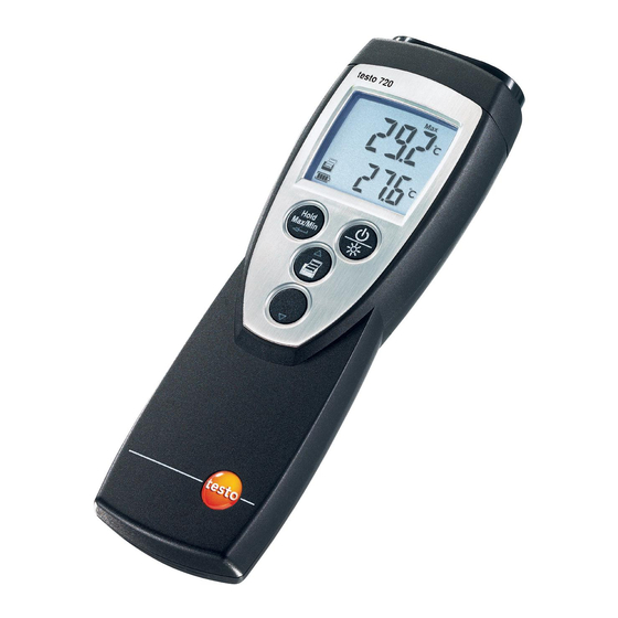
  • Page 41: Description Du Produit

    3. Description du produit Description du produit Ce chapitre fournit un aperçu des composants du produit et de ses fonctions. 3.1 Eléments d’affichage et de commande Aperçu ➀ Interface série,connecteurs pour sonde(s) ➁ Affichage ➂ Touche de fonction ➃ Compartiment pile (au dos) ➄...
  • Page 42: Eléments Importants De L'affichage

    3.2 Interfaces Interface infrarouge L'interface infrarouge dans la partie supérieure de l'appareil permet d'envoyer les données de mesure vers l'imprimante testo. Connecteur(s) pour sondes Les connecteurs pour sondes dans la partie supérieure de l'appareil permettent de raccorder des sondes de mesure.
  • Page 43: Mise En Service

    4. Mise en service Mise en service Ce chapitre décrit les étapes nécessaires à la mise en ser- vice du produit. ➣ Insérer la pile / l’accu : Ouvrez le compartiment pile au dos de l'appareil : Faites glisser le couvercle du compartiment pile dans le sens de la flèche puis retirez-le.
  • Page 44: Fonctionnement

    5. Fonctionnement Fonctionnement Ce chapitre décrit les manipulations devant souvent être effectuées lors de l'utilisation du produit. 5.1 Raccorder la sonde Sondes raccordables Les sondes avec raccord doivent être raccordées avant d'allumer l'appareil afin qu'elles puissent être reconnues par l'appareil de mesure. Raccordez la fiche de la sonde dans le connecteur de l'appareil de mesure.
  • Page 45: Paramétrage

    5. Fonctionnement 5.4 Paramétrage Ouvrir le mode configuration : ✓ L'appareil est allumé et il est en mode aperçu de mesure. Hold, Max ou Min ne sont pas activés. Maintenez appuyé (env. 2 s) jusqu'à ce que l'affichage change. - L'appareil est maintenant en mode configuration. Il est possible de passer à...
  • Page 46 5. Fonctionnement Paramétrer Auto Off: ✓ Le mode configuration est ouvert, Auto Off clignote. Sélectionnez l'option souhaitée avec validez avec · ON : L'appareil de mesure s'éteint automatique - ment après 10 mn de non activation de touche. Exception : une valeur de mesure maintenue affichée (Hold ou Auto Hold apparaissent).
  • Page 47: Mesures

    6. Mesures Mesures Ce chapitre décrit les étapes nécessaires à réaliser des mesures avec ce produit. ➣ Réaliser des mesures : ✓ L'appareil est allumé et se trouve en mode aperçu. Positionnez la sonde et lisez les valeurs mesurées. Lorsque la fonction alarme est activée et en cas de dépassement.
  • Page 48 Les valeurs mesurées affichées (valeur de mesure actuelle, valeur de mesure conservée ou valeurs Max/Min) peuvent être imprimées. Une imprimante testo est nécessaire (accessoire). Lorsque Impression Max/Min est en fonction, les valeurs minimales/maximales sont imprimées en complément de la valeur mesurée actuelle ou de la valeur figée.
  • Page 49: Maintenance Et Entretien

    7. Maintenance et entretien Maintenance et entretien Ce chapitre décrit les étapes contribuant au maintien des fonctionnalités et à la prolongation de la durée de vie du produit. ➢ Nettoyage du boîtier : En cas de salissure, nettoyez le boîtier avec un linge humide (eau savonneuse).
  • Page 50: Questions / Réponses

    · Passage sous létendue de · Respectez l’étendue mesure admissible de mesure admissible Au cas où nous n'aurions pu répondre à votre question : Veuillez vous adresser à votre revendeur ou au Service Après-vente Testo. Vos contacts figurent dans le carnet de garantie ou sur internet www.testo.fr.
  • Page 51: Caractéristiques Techniques

    9. Caractéristiques techniques Caractéristiques techniques Caractéristiques Valeurs Grandeurs Température (°C/ °F) Etendue de mesure Sonde Pt100 : -100...+800°C Sonde CTN : -50...+150°C Résolution 0.1°C / 0.1°F Précision de l’appareil Sonde Pt100 : (±1 digit) ±0.2 °C/ ±0.4 °F (-100.0...+199.9 °C / -48.0...+391.8°F) ±0.2% de val.
  • Page 52: Accessoires / Pièces De Rechange

    0609 1973 Sonde de surface, Pt100, étanche 0609 1773 Divers TopSafe testo 720 0516 0221 Vous trouverez une liste complète de tous les accessoires et toutes les pièces détachées dans nos catalogues produits et nos brochures, ou sur Internet sous :...
  • Page 56 SE @ Co. KGaA Postfach 11 40, 79849 Lenzkirch Testo-Straße 1, 79853 Lenzkirch Telefon: (0 76 53) 6 81 - 0 Fax: (0 76 53) 6 81 - 1 00 E-Mail: info@testo.de Internet: www.testo.com 0977 7200 04 de en fr...

Table des Matières