Table des Matières
Publicité
Les langues disponibles
Les langues disponibles
Liens rapides
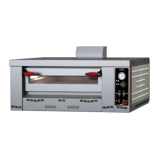
FORNO STATICO A GAS
FOUR STATIQUE À GAZ
STATIC GAS OVEN
СТАТИЧЕСКАЯ ГАЗОВАЯ ПЕЧЬ
HORNO ESTÁTICO A GAS
STATISCHER GASOFEN
Regolamento (UE) 2016/426 del 9 Marzo 2016
Regulation (UE) 2016/426 of 9 March 2016
IT
Manuale di istruzioni, uso e manutenzione
(Istruzioni originali)
FR
Manuel d'instructions, d'utilisation et d'entretien
(Traduction de la notice originale)
EN
Instruction, use and maintenance manual
(Translation of the original instructions)
Руководство по эксплуатации и техническому обслуживанию
RU
(Перевод оригинальной инструкции)
ES
Manual de instrucciones, uso y manutención
(Traducción de las instrucciones originales)
DE
Bedienungs-, Gebrauchs- und Wartungsanleitung
(Übersetzung der Originalanleitung)
FLAME 4 - FLAME 6 - FLAME 9
Publicité
Chapitres
Table des Matières

Manuels Connexes pour ChefLine FLAME 4

Sommaire des Matières pour ChefLine FLAME 4
- Page 1 HORNO ESTÁTICO A GAS STATISCHER GASOFEN Regolamento (UE) 2016/426 del 9 Marzo 2016 Regulation (UE) 2016/426 of 9 March 2016 FLAME 4 - FLAME 6 - FLAME 9 Manuale di istruzioni, uso e manutenzione (Istruzioni originali) Manuel d'instructions, d'utilisation et d'entretien...
- Page 3 Istruzioni originali Categoria / Category: II2H3+ Tipo di installazione / Type of installation: FLAME4: A1- B11- B21 FLAME 6-9: B11- B21...
-
Page 4: Table Des Matières
INDICE PREMESSA ................................6 SIMBOLOGIA ..............................6 DESTINAZIONE D’USO ........................... 6 SCOPO E CONTENUTO DEL MANUALE ....................... 6 CONSERVAZIONE DEL MANUALE ........................ 6 AGGIORNAMENTO DEL MANUALE ......................7 GENERALITÀ ..............................7 PRINCIPALI NORMATIVE E DIRETTIVE RISPETTATE E DA RISPETTARE ..........7 GARANZIA LEGALE ............................ - Page 5 FASI DI LAVORO ............................32 FASE DI SPEGNIMENTO ..........................33 MANUTENZIONE E PULIZIA ..........................33 PRECAUZIONI DI SICUREZZA ........................33 MANUTENZIONE ORDINARIA RIVOLTA ALL’UTILIZZATORE ..............33 8.2.1 Pulizia del piano refrattario della camera di cottura ................33 8.2.2 Pulizia esterna del forno ........................33 MANUTENZIONE STRAORDINARIA RIVOLTA AI TECNICI ...............
-
Page 6: Premessa
1. PREMESSA Gentile cliente, desideriamo innanzitutto ringraziarLa per la preferenza che ha voluto accordarci acquistando il nostro prodotto e ci congratuliamo con Lei per la scelta. Per consentirle di utilizzare al meglio il suo nuovo Forno, la invitiamo a seguire attentamente quanto descritto nel presente manuale. -
Page 7: Aggiornamento Del Manuale
Cessione dell’apparecchiatura: In caso di cessione dell’apparecchiatura l’utente è obbligato a consegnare al nuovo acquirente anche il presente manuale. 1.5 AGGIORNAMENTO DEL MANUALE Il presente manuale rispecchia lo stato dell’arte al momento dell’emissione sul mercato del prodotto. Le apparecchiature già presenti sul mercato, con relativa documentazione tecnica, non verranno considerate dalla casa costruttrice carenti o inadeguate a seguito di eventuali modifiche, adeguamenti o applicazione di nuove tecnologie su apparecchiature di nuova commercializzazione. -
Page 8: Garanzia Legale
Norme EN 203-1, EN 203-2-2, EN 203-3 “Apparecchi per cucine professionali alimentati a gas”; Norma EN 437 Gas di prova – Pressioni di prova – Categorie di apparecchi; Direttiva 2014/35/CE “Concernente il ravvicinamento delle legislazioni degli Stati membri relative al materiale elettrico destinato ad essere adoperato entro taluni limiti di tensione e che abroga la direttiva 2006/95/CE”;... -
Page 9: Caratteristiche Dell'utilizzatore
CARATTERISTICHE DELL’UTILIZZATORE 1.10 L’utilizzatore dell’apparecchiatura deve essere una persona adulta e responsabile, provvista delle conoscenze tecniche necessarie per la manutenzione ordinaria, come ad esempio la pulizia giornaliera. Tenere lontano i bambini e i non addetti, mentre l’apparecchiatura è in funzione. 1.11 ASSISTENZA TECNICA Il Costruttore è... -
Page 10: Consegna Del Forno
Sull’ apparecchiatura è inoltre presente la seguente targhetta che riporta le principali avvertenze di sicurezza: L’ apparecchio deve essere allacciato conformemente alle regolamentazioni in vigore e usato solo in locali ben areati. Si presti particolarmente attenzione alle istruzioni per l’uso e la manutenzione prima di metterlo in funzione. -
Page 11: Avvertenze Per Il Manutentore
Essere asciutto; Fonti idriche e di calore adeguatamente distanti; Ventilazione ed illuminazione adeguata e rispondenti alle norme igieniche e di sicurezza previste dalle leggi vigenti; Il pavimento deve essere piano e compatto per favorire una pulizia accurata; ... -
Page 12: Specifiche Generali
3. SPECIFICHE GENERALI 3.1 Caratteristiche Il forno a gas per pizza è ad uso esclusivamente professionale i cui pannelli esterni, opportunamente dotati di asole e fori di aerazione, sono realizzati in ferro verniciato. Il forno è dotato di una camera di cottura con delle piastre refrattarie sulle quali possono essere introdotte contemporaneamente da quattro a nove pizze standard, in base al modello. - Page 13 Dimensioni esterne (cm) Larghezza Profondità Altezza Dimensioni camera di cottura (cm) Larghezza Profondità Altezza Peso (kg) Ø SCARICO FUMI (cm) DATI ELETTRICI Tensione di Frequenza Potenza massima assorbita alimentazione Cavo elettrico (Hz) 220-230 50/60 3 x 0.75 mm Altri dati Raccordo di collegamento gas Raccordo di collegamento gas Raccordo di collegamento gas...
-
Page 14: Schemi Elettrici
3.3 Schemi elettrici... - Page 16 Legenda - Legend Symbol Descrizione Description Linea di Fase Phase line Linea di Neutro Neutral line Filtro EMC EMC filter Termostato di sicurezza a riarmo manuale Manual reset safety thermostat Interruttore generale Main switch Morsettiera Branching terminal board Interruttore luce Chamber light switch Trasformatore Transformer...
-
Page 17: Movimentazione E Trasporto
4. MOVIMENTAZIONE E TRASPORTO L’ apparecchiatura viene fornita completa di tutte le sue parti previste in un apposito imballo chiuso e fissata con delle regge ad una pedana (pallet) in legno. Lo scarico e la movimentazione del forno deve essere fatta tramite un carrello elevatore da personale qualificato. -
Page 18: Luogo Di Installazione Del Forno
5.2 LUOGO DI INSTALLAZIONE DEL FORNO Nella figura di seguito sono indicate le distanze minime che devono essere rispettate nel posizionamento per facilitare le operazioni d’uso, pulizia e manutenzione del forno, nonché per una corretta ventilazione. Mantenere una distanza di minimo 25 cm tra il forno e le pareti laterali del locale, dove possibile almeno 50 cm sul lato destro per poter accedere comodamente all’impianto elettrico in caso di manutenzione e/o riparazione. -
Page 19: Messa A Terra
6.2.1.1 Messa a terra È obbligatorio che l’impianto sia provvisto di messa a terra. 6.2.2 Collegamento alla rete del gas Prima di collegare il forno all‘impianto del gas, controllare i requisiti del forno in materia di alimentazione del gas. Le specifiche per il tipo di predisposizione riportate sull’ apposita targhetta (vedi ... - Page 20 Nota: nei modelli di forni pizza FLAME 4 e FLAME 6, il dispositivo rompi tiraggio (camino antivento) è già integrato nel terminale di scarico fumi incorporato al forno. Nel modello FLAME 9 il dispositivo rompi tiraggio è...
- Page 21 Schema esemplificativo di un installazione del tipo B11 valido per i Modelli FLAME 4 e FLAME 6 Nei modelli di forni pizza FLAME 4 e FLAME 6, il dispositivo rompi tiraggio (camino antivento) è già integrato nel terminale di scarico fumi incorporato ai forni.
- Page 22 Per l’installazione B21, sotto cappa asservita, non serve alcun tratto di tubo verticale e non viene richiesto il dispositivo rompi tiraggio utilizzato per il forno FLAME 9. I forni FLAME 4 e FLAME 6 hanno già il dispositivo rompi tiraggio integrato nel terminale di scarico e non deve essere rimosso.
-
Page 23: Forni Sovrapposti
Flame 9 oven Gas G30 Gas G20 Gas G25 Gas G25.1 Gas G25.3 Pressione fumi al camino [Pa] Pressure of the smoke at the chimney -1.9 -1.8 -1.8 -1.9 -1.5 [Pa] Temperatura fumi al camino [°C] Temperature of the smoke at the chimney [°C] Massa fumi [g/s] 52.45... -
Page 24: Controllo Della Pressione Di Alimentazione E Della Portata Termica
Nota: nei modelli di forni pizza FLAME 4 e FLAME 6, la sovrapposizione di due forni comporta che il forno inferiore sia dotato di un tubo verticale inclinato (a 45°) in modo da poter scaricare i fumi lontano dal terminale di scarico del forno superiore evitando così... - Page 25 Tutte le regolazioni devono essere fatte nell’ordine riportato Verificare le pressioni in ingresso ed in uscita mediante le apposite prese di misura. A controllo effettuato chiudere la tenuta con le apposite viti. Coppia di serraggio consigliata: 1.0 Nm. 1. Togliere il cappuccio di plastica E del modulatore. 2.
- Page 26 Per la verifica delle pressioni confrontare i dati rilevati con i valori riportati nella seguenti tabelle. Tabella dati tecnici 1 – Dati nominali FLAME 4 Consumi del Pressione Pressione gas al MAX all’uscita all’uscita Pressione Portata Portata (con il potere...
-
Page 27: Conversione Ad Altro Tipo Di Gas
Tabella dati tecnici 1 – Dati nominali FLAME 9 Consumi del Pressione Pressione gas al MAX all’uscita all’uscita Pressione Portata Portata (con il potere nominale termica termica valvola valvola calorifico Regolatore Tipo ingresso nominale ridotta (al MAX) (al MIN) inferiore) di pressione di gas Nominal... - Page 28 Prima di procedere alla sostituzione dell‘iniettore, verificare che in esso sia stampigliato il diametro corretto (espresso in 1/100 di mm) e che sia corrispondente a quanto indicato nella tabella dei dati tecnici (vedi tab.2). Tabella dati tecnici 2 – Iniettori e regolazioni FLAME 4 Pressione in Regolazione boccola Tipo di...
- Page 29 Tabella dati tecnici 2 – Iniettori e regolazioni FLAME 9 Pressione in Regolazione boccola Tipo di Diametro iniettore entrata aria primaria (H) Injector diameter Inlet pressure Primary air bush setting (H) (1/100 mm) Gas type (mbar) (mm) G25.1 G25.3 G30/G31 28-30/37 G30, G31 G30, G31...
-
Page 30: Avvertenze
II2EK3B/P G25.3 3B/P G30, G31 28-30 II2HS3B/P 3B/P G30, G31 28-30 II2E3B/P 3B/P G30, G31 IS-CY-MT I3B/P 3B/P G30, G31 28-30 LU-BE-FR G30/G31 28-30/37 20/25 35/45 I2E(R) 2E(R) G20/G25 20/25 17/20 25/30 I2Esi 2Esi G20/G25 20/25 17/20 25/30 AVVERTENZE: Dopo l’adattamento ad altro gas è necessario: ... -
Page 31: Prima Accensione Del Forno
Quadro comandi con termometro digitale: A) INTERRUTTORE GENERALE B) INTERRUTTORE STAND-BY FORNO C) TERMOMETRO DIGITALE D) TERMOSTATO MECCANICO E) SPIA RAGGIUNGIMENTO TEMPERATURA F) SPIA PRESENZA TENSIONE ELETTRICA G) SPIA ALLARME SPEGNIMENTO E PULSANTE DI RIARMO H) INTERRUTTORE LUCE CAMERA 7.2 PRIMA ACCENSIONE DEL FORNO PER UNA CORRETTA ACCENSIONE DEL FORNO LASCIARE LA PORTA APERTA FINO A QUANDO IL TERMOMETRO INDICA LA TEMPERATURA DI 200°... -
Page 32: Consigli Del Pizzaiolo
In particolare per quanto riguarda la pizza ed i prodotti similari, i tempi e le temperature di cottura dipendono dalla forma e dallo spessore della pasta, non ché dalla quantità e tipologia degli ingredienti aggiunti. Per tali motivi e sempre consigliabile effettuare preventivamente alcune prove di cottura, (in particolar modo quando si utilizza per la prima volta questo modello di forno), al fine di comprenderne al meglio le caratteristiche ed il funzionamento. -
Page 33: Fase Di Spegnimento
Evitare di far cadere oli e grassi sul fondo in quanto portati ad alte temperatura si possono incendiare. 7.7 FASE DI SPEGNIMENTO Per spegnere il forno ruotare la manopola del termostato (D) in posizione 0, dopo di che portare l’interruttore generale (A) in posizione 0. -
Page 34: Allarmi E Possibili Anomalie
8.3 MANUTENZIONE STRAORDINARIA RIVOLTA AI TECNICI Qualsiasi intervento di manutenzione straordinaria e di sostituzione di componenti, non può essere effettuato dall’utilizzatore del forno, ma deve essere realizzata esclusivamente da un tecnico specializzato. Il tecnico è tenuto ad utilizzare esclusivamente ricambi originali, a tal proposito fare riferimento all’elenco riportato nel capitolo ESPLOSI e LISTA RICAMBI. -
Page 35: Informazioni Per La Demolizione E Lo Smaltimento
10. INFORMAZIONI PER LA DEMOLIZIONE E LO SMALTIMENTO La demolizione e lo smaltimento della macchina sono ad esclusivo carico e responsabilità del proprietario che dovrà agire in osservanza delle leggi vigenti nel proprio Paese in materia di sicurezza, rispetto e tutela dell’ambiente. Smantellamento e smaltimento possono essere affidati anche a terzi, purché... - Page 36 Traduction de la notice originale Catégorie / Category: II2H3+ Type d'installation / Type of installation: FLAME4 : A1- B11- B21 FLAME 6-9 : B11- B21...
- Page 37 SOMMAIRE AVANT-PROPOS .................................. 39 SYMBOLES .................................. 39 DESTINATION D'USAGE ............................39 BUT ET CONTENU DU MANUEL ..........................39 CONSERVATION DU MANUEL ..........................39 MISE À JOUR DU MANUEL ............................40 GÉNÉRALITÉ ................................40 PRINCIPALES NORMES ET DIRECTIVES RESPECTÉES ET À RESPECTER ..........40 GARANTIE LÉGALE ..............................
- Page 38 CONSEILS DU PIZZAIOLO ............................65 PHASES DE TRAVAIL..............................65 PHASE D'EXTINCTION .............................. 66 ENTRETIEN ET NETTOYAGE ............................66 PRÉCAUTIONS DE SÉCURITÉ ..........................66 ENTRETIEN ORDINAIRE SOUS LA RESPONSABILITÉ DE L’UTILISATEUR ..........66 Nettoyage de la sole réfractaire de la chambre de cuisson..............66 8.2.1 8.2.2 Nettoyage externe du four ..........................
-
Page 39: Avant-Propos
1. AVANT-PROPOS Cher Client, nous souhaitons avant tout vous remercier de la préférence que vous nous avez accordée en achetant nos produits, et nous nous réjouissons de ce choix. Pour vous permettre de tirer le meilleur parti de votre nouveau four, nous vous recommandons de suivre les instructions figurant dans ce manuel. -
Page 40: Mise À Jour Du Manuel
1.5 MISE À JOUR DU MANUEL Le présent manuel correspond à l'état de l'art au moment de l'émission sur le marché du produit. Les appareils déjà présents sur le marché, avec relative documentation technique, ne seront pas considérés par le fabricant comme incomplets ou inadéquats suite à d'éventuelles modifications, adaptations ou application de nouvelles technologies sur des appareils de nouvelle commercialisation. -
Page 41: Garantie Légale
Directive 2014/35/CE « Relative à l'harmonisation des législations des États membres concernant le matériel électrique destiné à être employé dans certaines limites de tension et abrogeant la Directive 2006/95/CE » ; Directive 2014/30/UE « Relative à l'harmonisation des législations des États membres concernant la compatibilité... -
Page 42: Caractéristiques De L'utilisateur
1.10 CARACTÉRISTIQUES DE L'UTILISATEUR L’utilisateur de l'appareil doit être une personne adulte et responsable pourvue des connaissances techniques nécessaires pour l'entretien ordinaire, comme par exemple le nettoyage quotidien. Éloigner les enfants et tous ceux qui ne sont pas autorisés à l'utilisation de l'appareil pendant son fonctionnement. -
Page 43: Livraison Du Four
Sur l'appareil est en outre présente la plaquette suivante reportant les principaux avertissements pour la sécurité: L'appareil doit être raccordé conformément aux réglementations en vigueur et utilisé uniquement dans des locaux bien aérés. Faire particulièrement attention aux instructions concernant l'utilisation et l'entretien avant de le mettre en marche. Les plaquettes ne doivent en aucun cas être retirées (tout au plus il est possible de mettre à... -
Page 44: Recommandations Pour Le Personnel D'entretien
Endroit sec ; Sources d'eau et de chaleur adéquatement éloignées ; Ventilation et éclairage adaptés et satisfaisant les normes d’hygiène et de sécurité requises par la législation ; Le sol doit être plat et compact pour faciliter un nettoyage en profondeur ; ... -
Page 45: Spécifications Générales
3. SPÉCIFICATIONS GÉNÉRALES 3.1 Caractéristiques Le four à gaz pour pizza est un four professionnel et les panneaux externes, équipés de fentes et de trous d'aération, sont réalisés en fer peint. Le four est équipé d'une chambre de cuisson avec des plaques réfractaires sur lesquelles peuvent être introduites en même temps quatre à... - Page 46 Dimensions externes (cm) Largeur Profondeur Hauteur Dimensions de la chambre de cuisson (cm) Largeur Profondeur Hauteur Poids (kg) Ø ÉVACUATION FUMÉES (cm) DONNÉES ÉLECTRIQUES Tension d'alimentation Fréquence Puissance maximum absorbée Câble électrique (Hz) 220-230 50/60 3 x 0.75 mm2 Autres données Raccord de branchement gaz Raccord de branchement gaz Raccord de branchement gaz...
-
Page 47: Schémas De Câblage
3.3 Schémas de câblage... - Page 49 Légende - Legend Symbole Description Description Ligne de Phase Phase line Ligne de Neutre Neutral line Filtre EMC EMC filter Thermostat de sécurité à réarmement manuel Manual reset safety thermostat Interrupteur général Main switch Plaque à bornes Terminal board Interrupteur lumière Light switch Transformateur Transformer...
-
Page 50: Manutention Et Transport
4. MANUTENTION ET TRANSPORT L'appareil est fourni avec toutes les pièces prévues dans un emballage spécial fermé et fixé avec des supports à une palette en bois. Le déchargement et la manutention du four doivent être effectués en utilisant un chariot élévateur manié par du personnel qualifié. -
Page 51: Lieu D'installation Du Four
5.2 LIEU D'INSTALLATION DU FOUR Dans la figure ci-après sont indiquées les distances minimales qui doivent être respectées lors du placement afin de faciliter les opérations d'utilisation, de nettoyage et d'entretien du four, ainsi que pour une correcte ventilation. Maintenir une distance minimale de 25 cm entre le four et les parois latérales du local, là... -
Page 52: Mise À La Terre
6.2.1.1 Mise à la terre L'installation doit obligatoirement être pourvue de mise à la terre. 6.2.2 Raccordement au réseau de gaz Avant de raccorder le four à l'installation du gaz, contrôler les caractéristiques requises du four en matière d'alimentation du gaz. Les spécifications pour le type de pré-installation sont reportées sur la plaquette prévue à... - Page 53 La rupture projet de dispositif (équipé avec le vent), en cas de B11 d'installation est nécessaire pour assurer la fonctionnalité de l'appareil en présence d'obstruction des voies respiratoires ou autrement à travers le tuyau système / échappement à l'extérieur. Exemple schématique d'une installation de type A1 valable que pour le modèle FLAME 4...
- Page 54 Exemple schématique d'une installation de la B11 de type valide pour les modèles FLAME4 et FLAME6 Dans les modèles de fours à pizza FLAME 4 et FLAME 6, le projet de rupture de l'appareil (équipé avec le vent) est déjà intégré dans le terminal de combustion des fours encastrables.
-
Page 55: Paramètres À La Cheminée / Chimney Parameters
Pour installer B21, asservis sous le capot, vous n'avez pas besoin de coupe verticale du tuyau n'est pas nécessaire et le dispositif utilisé pour briser projet FLAME four 9. Fours FLAME 4 et FLAMME 6 ont déjà été intégrés dans la pause de l'appareil projet échappement et ne doit pas être enlevé. - Page 56 Flame 9 oven Gaz G30 Gaz G20 Gaz G25 Gaz G25.1 Gaz G25.3 Pression fumées à la cheminée [Pa] -1.9 -1.8 -1.8 -1.9 -1.5 Chimney smoke pressure [Pa] Température fumées à la cheminée [°C] Chimney smoke temperature [°C] Masse fumées [g/s] 52.45 50.78 56.68...
-
Page 57: Contrôle De La Pression D'alimentation Et De La Portée Thermique
NB. : dans les modules de fours pizza FLAME 4 et FLAME 6, la superposition de deux fours fait que le four inférieur est équipé d'un tube vertical incliné (à 45°) de manière à pouvoir évacuer les fumées loin du terminal d'évacuation du four supérieur en évitant ainsi d'en déranger le tirage. - Page 58 Tous les réglages doivent être effectués dans l'ordre mentionnés Vérifier les pressions en entrée et en sortie avec les prises de mesure adaptées. Une fois le contrôle terminé fermer de manière étanche avec les vis. Couple de serrage conseillé : 1.0 Nm. 6.
- Page 59 Pour vérifier les pressions comparer les données recueillies avec les valeurs mentionnées dans le tableau suivant. Tableau des données techniques 1 - Données nominales FLAME 4 Consommation Pression Pression de gaz au MAX Pression Débit Débit à la sortie à la sortie...
-
Page 60: Conversion À Un Autre Type De Gaz
Tableau des données techniques 1- Données nominales FLAME 9 Consommation Pression Pression de gaz au MAX Pression Débit Débit à la sortie à la sortie (avec le nominale calorifique calorifique vanne vanne pouvoir Régulateur Type entrée nominal réduit (au MAX) (au MIN) calorifique de pression... - Page 61 diamètre correct (exprimé en 1/100 de mm) et qu'il corresponde à ce qui est indiqué dans le tableau des données techniques (voir tableau 2). Tableau des données techniques 2 -Injecteurs et réglages FLAME 4 Réglage douille Type de Pression en entrée Diamètre injecteur...
- Page 62 Tableau des données techniques 2 -Injecteurs et réglages FLAME 9 Réglage douille Type de Pression en entrée Diamètre injecteur air primaire (H) Inlet pressure Injector diameter Primary air bush (mbar) (1/100 mm) Gas type adjustment (H) (mm) G25.1 G25.3 G30/G31 28-30/37 G30, G31 G30, G31...
-
Page 63: Mise En Service Et Utilisation Du Four
II2HS3B/P 3B/P G30, G31 28-30 II2E3B/P 3B/P G30, G31 IS-CY-MT I3B/P 3B/P G30, G31 28-30 LU-BE-FR G30/G31 28-30/37 20/25 35/45 I2E(R) 2E(R) G20/G25 20/25 17/20 25/30 I2Esi 2Esi G20/G25 20/25 17/20 25/30 ATTENTION : Après l'adaptation à un autre gaz il faut : ... -
Page 64: Première Mise En Route Du Four
Panneau de commandes avec thermomètre numérique : INTERRUPTEUR GÉNÉRAL J) INTERRUPTEUR STAND-BY FOUR K) THERMOMÈTRE NUMÉRIQUE L) THERMOSTAT MÉCANIQUE M) VOYANT TEMPÉRTURE ATTEINTE N) VOYANT PRÉSENCE TENSION ÉLECTRIQUE O) VOYANT ALARME EXTINCTION ET BOUTON DE RÉARMEMENT P) INTERRUPTEUR LUMIÈRE CHAMBRE PREMIÈRE MISE EN ROUTE DU FOUR POUR UNE CORRECT ALLUMAGE LAISSER LE PORTE OUVERTE JUSQU'A LA TEMPÉRATURE ARRIVE A 200 °... -
Page 65: Conseils Du Pizzaiolo
En particulier pour ce qui concerne la pizza et les produits similaires, les temps et les températures de cuisson varient en fonction de la forme et de l'épaisseur de la pâte, ainsi que de la quantité et du type des ingrédients ajoutés. -
Page 66: Phase D'extinction
PHASE D'EXTINCTION Pour éteindre le four, tourner la manette du thermostat (D) sur la position 0° et amener l'interrupteur général (A) sur la position 0. 8. ENTRETIEN ET NETTOYAGE 8.1 PRÉCAUTIONS DE SÉCURITÉ Avant d'effectuer toute opération d'entretien, adopter les précautions suivantes: ... -
Page 67: Alarmes Et Anomalies Possibles
Le technicien ne doit utiliser que des pièces de rechange originales. Pour cela, se référer à la liste reportée au chapitre 10 (ÉCLATÉ ET PIÈCES DE RECHANGE). Débrancher le four et fermer l'alimentation du gaz avant chaque intervention sur le four. 9. -
Page 68: Information Sur La Démolition Et L'élimination
10. INFORMATION SUR LA DÉMOLITION ET L'ÉLIMINATION La démolition et l'élimination de la machine sont une charge et une responsabilité exclusives du propriétaire qui devra agir conformément aux lois en matière de sécurité, respect et sauvegarde de l'environnement en vigueur dans son pays. Le démantèlement et l'élimination peuvent être confiés à... - Page 69 Translation of the original instructions Categoria / Category: II2H3+ Tipo di installazione / Type of installation: FLAME 4: A1 - B11 - B21 Flame 6-9: B11 - B21...
- Page 70 TABLE OF CONTENTS PREMISE ................................72 SYMBOLS ............................... 72 INTENDED USE .............................. 72 MANUAL PURPOSE AND CONTENT ......................72 STORING THE MANUAL ..........................72 UPDATING THE MANUAL ..........................72 OVERVIEW ..............................73 MAIN REGULATIONS AND DIRECTIVES THAT ARE RESPECTED AND MUST BE RESPECTED..73 LEGAL GUARANTEE ............................
- Page 71 SWITCH-OFF PHASE ............................ 98 MAINTENANCE AND CLEANING ......................... 98 SAFETY PRECAUTIONS ..........................98 ROUTINE MAINTENANCE TO BE PERFORMED BY THE USER ............... 98 8.2.1 Cleaning the refractory surface of the cooking chamber ..............99 8.2.2 Externally cleaning the oven ........................ 99 UNPLANNED MAINTENANCE TO BE PERFORMED BY TECHNICIANS ..........
-
Page 72: Premise
1. PREMISE Dear Customer, first of all we would like to thank you for choosing our product and congratulate you on your choice. To allow you to make the most of your new oven, please follow the instructions in this manual carefully. The ovens referred to in this manual have been exclusively designed to cook pizzas and similar products. -
Page 73: Overview
The equipment that is already available on the market, with the relative technical documentation, will not be considered incomplete or inappropriate due to possible subsequent modifications, adjustments or application of new technologies on newly marketed machines. The information in this manual only applies for models in the II2H3+ category and that are used in Italy. If used in another European country with a different category, the manual must be translated with the references (setup for the gas and local installation regulations) for the country of destination. -
Page 74: Legal Guarantee
Directive 85/374/EEC and Directive 1999/34/EC “on the approximation of the laws, regulations and administrative provisions of the Member States concerning liability for damage resulting from defective products”; Directive 2002/95/EC “on the restriction of the use of certain hazardous substances in electrical and electronic equipment”;... -
Page 75: Spare Parts
1.12 SPARE PARTS Use only original spare parts. Do not wait until components are worn out before replacing them. Replacing a worn component before breakage helps to prevent injuries deriving from accidents caused by unexpected component breakage, which could provoke serious damage to persons or property. ... -
Page 76: Oven Delivery
Outside the package, there is a plate that provides information about the current gas setup in addition to information about the country of destination and the safety warnings. This plate may be disposed of together with the package according to current national regulations. 1.14 OVEN DELIVERY The oven is supplied in a closed cardboard package bound with straps to a wooden platform that can be moved... -
Page 77: Warnings For The Maintenance Technician
Furthermore, the user must take heed of the following: Make sure that children do not approach the oven when it is in use; Comply with the instructions provided in this Manual. Do not remove or tamper with the oven safety devices; ... -
Page 78: General Specifications
3. GENERAL SPECIFICATIONS 3.1 Features The gas pizza oven is for professional use only and its external panels with specific slots and ventilation holes, are made of painted iron. The oven is equipped with a cooking chamber featuring refractory plates that can receive from four to nine standard pizzas at the same time, depending on the model. - Page 79 External dimensions (cm) Width Depth Height Cooking chamber dimensions (cm) Width Depth Height Weight (kg) Ø FLUE GAS (cm) ELECTRIC DATA Supply voltage Frequency Maximum power absorbed Power cable (Hz) 220-230 50/60 3 x 0.75 mm Other data Gas connection fitting Gas connection fitting Gas connection fitting ½”...
-
Page 80: Wiring Diagrams
3.3 Wiring diagrams... - Page 82 Legenda - Key Symbol Descrizione Linea di Fase Phase line Linea di Neutro Neutral line Filtro EMC EMC filter Termostato di sicurezza a riarmo manuale Manual reset safety thermostat Interruttore generale Main switch Morsettiera Terminal board Interruttore luce Light switch Trasformatore Transformer LDX-LSX...
-
Page 83: Handling And Transport
4. HANDLING AND TRANSPORT The appliance is supplied complete with all its parts in a special closed packaging that is fixed with straps to a wooden platform (pallet). The oven must be unloaded and handled by a qualified forklift operator. To transport the oven to the installation site, use a wheeled trolley with a suitable capacity. -
Page 84: Oven Installation Site
5.2 OVEN INSTALLATION SITE The figure below shows the minimum distances that must be respected when positioning the oven in order to make using, cleaning and maintaining the oven easier, in addition to allowing for proper ventilation. Keep a distance of at least 25 cm between the oven and the room’s side walls, and where possible, leave at least 50 cm on the right side so that the electrical system can easily be accessed for maintenance and/or repairs. -
Page 85: Earth Connection
6.2.1.1 Earth connection It is mandatory that the electrical system is equipped with an earth connection. 6.2.2 Connection to the gas network Before connecting the oven to the gas system, check the oven's requirements relating to the gas supply. The specifications for the type of setup are shown on the plate (see paragraph 1.13). The oven is equipped with a cylindrical ½... - Page 86 Note: in models of ovens pizza FLAME FLAME 4 and 6, the device break draft (equipped with wind) is already integrated in the exhaust fumes embedded in the oven. In the model the device FLAME 9 break draft is a separate accessory that must be arranged in case of installation of the type B11.
- Page 87 The vertical section of pipe can be reduced to installation requirements, it is important not to use 90 ° bends right after the break draft device. Schematic example of an installation of the type B11 FLAME valid for Models FLAME 4, FLAME 6 and FLAME 9.
- Page 88 PARAMETRI AL CAMINO / CHIMNEY PARAMETERS Flame 4 oven Gas G30 Gas G20 Gas G25 Gas G25.1 Gas G25.3 Pressione fumi al camino [Pa] -2.0 -1.8 -2.1 -2.1 -2.2 Chimney smoke pressure [Pa] Temperatura fumi al camino [°C] Chimney smoke temperature [°C] Massa fumi [g/s] 41.00...
- Page 89 Please note: In the FLAME 4 and FLAME 6 pizza oven models, the superimposition of the two ovens means that the lower oven is equipped with an inclined vertical tube (at 45°) in order to be able to discharge the smoke away from the...
-
Page 90: Checking The Supply Pressure And Heat Input
6.2.4 Checking the supply pressure and heat input Before checking the supply pressure, make sure that the gas has been set up correctly on site. The pressure (connection and output) must be measured when the oven is running, i.e. the burner must be switched on. - Page 91 Warning: The cap [E] must be repositioned in order for the modulator to work properly. To check the pressures, compare the data obtained with the values shown in the following tables. Technical data table 1 - FLAME 4 nominal data Consumi del...
- Page 92 Technical data table 1 - FLAME 6 nominal data Consumi del gas al MAX Pressione Pressione (con il potere all’uscita all’uscita Pressione Portata Portata calorifico nominale termica termica valvola valvola Regolatore Tipo inferiore) ingresso nominale ridotta (al MAX) (al MIN) di pressione di gas Nominal...
-
Page 93: Converting To Another Type Of Gas
6.2.5 Converting to another type of gas The conversion to another gas must be carried out by an authorised technician. The oven comes from the manufacturer designed for use with methane gas, unless otherwise specified by the customer. The oven is supplied with an injector kit (nozzles) for adapting to a different type of gas (Liquid Gas). Before proceeding with the conversion, close the gas supply and disconnect the oven from the electrical mains. - Page 94 Technical data table 2 - FLAME 4 injectors and adjustments Regolazione boccola Pressione in Tipo di Diametro iniettore aria primaria (H) entrata Injector diameter Primary air bush Inlet pressure (1/100 mm) Gas type adjustment (H) (mbar) (mm) G25.1 G25.3 G30/G31...
- Page 95 The primary air adjustment is performed by unscrewing the fixing screw (V) and modifying the distance (H) of the air bush (B) as shown in the following figure, according to the manufacturer’s instructions (see table 2). Once the adjustment has been made, retighten the screw (V). Technical data table 3 - Countries with their relative categories and inlet pressures Pressione Pressione...
-
Page 96: Commissioning And Using The Oven
7. COMMISSIONING AND USING THE OVEN 7.1 DIAGRAM OF THE CONTROL PANEL Control panel with a mechanical thermometer: A) MAIN SWITCH B) OVEN STANDBY SWITCH C) MECHANICAL THERMOMETER D) MECHANICAL THERMOSTAT E) TEMPERATURE REACHED INDICATOR LIGHT F) ELECTRIC POWER SUPPLY INDICATOR LIGHT G) ALARM SWITCH-OFF INDICATOR LIGHT AND RESET BUTTON H) CHAMBER LIGHT SWITCH... -
Page 97: Switching On The Oven For The First Time
7.2 SWITCHING ON THE OVEN FOR THE FIRST TIME FOR A GOOD STARTUP OF THE OVEN, KEEP THE DOOR OPEN UNTIL THE THERMOMETER DOESN'T SHOWING 200° C When the equipment is used for the first time, it is advisable to heat the oven when empty to eliminate bad smells caused by the evaporation of the refractory stones and the inner metallic parts. -
Page 98: Work Phases
For an optimal result it is better to always change the area occupied by the previous batch. This solution enables the refractory stone to dry correctly, creating a homogenous temperature in the entire area. 7.6 WORK PHASES With the oven operating, the temperature parameters can be changed at any time; in addition, the pizza baking operation can be verified by turning on the light in the chamber. -
Page 99: Cleaning The Refractory Surface Of The Cooking Chamber
8.2.1 Cleaning the refractory surface of the cooking chamber Cleaning operations must be carried out at the end of each use in compliance with the hygiene standards and to protect the machine’s functionality. Before proceeding, heat the oven to a temperature of 350°C for approximately 60 minutes to promote the carbonisation of the cooking residue. -
Page 100: Alarms And Possible Anomalies
9. ALARMS AND POSSIBLE ANOMALIES MALFUNCTIONS Anomaly Possible Cause Solution Check the main contactor, socket, plug No electricity in the mains. and power cable. The oven does not switch on The main switch is off (positioned to Turn the main switch to position “1”. and the digital thermometer “0”). -
Page 101: Information For Demolition And Disposal
10. INFORMATION FOR DEMOLITION AND DISPOSAL The demolition and disposal of the machine are the sole responsibility and responsibility of the owner who must act in compliance with the laws in force in his country concerning safety, respect and protection of the environment. Dismantling and disposal may also be entrusted to third parties, provided that recourse is always made to companies authorized to recover and eliminate the materials in question. - Page 102 Перевод оригинальной инструкции Категория / Category: II2H3+ Тип установки / Type of installation: FLAME4: A1- B11- B21 FLAME 6-9: B11- B21...
- Page 103 ОГЛАВЛЕНИЕ ПРЕДИСЛОВИЕ ..............................105 УСЛОВНЫЕ ОБОЗНАЧЕНИЯ ........................105 НАЗНАЧЕНИЕ ............................. 105 ЦЕЛЬ И СОДЕРЖАНИЕ РУКОВОДСТВА....................105 ХРАНЕНИЕ РУКОВОДСТВА ........................105 ОБНОВЛЕНИЕ РУКОВОДСТВА ........................ 106 ОБЩИЕ СВЕДЕНИЯ ........................... 106 ОСНОВНЫЕ ПРАВИЛА И ДИРЕКТИВЫ, КОТОРЫЕ БЫЛИ СОБЛЮДЕНЫ И ПОДЛЕЖАТ СОБЛЮДЕНИЮ ..............................106 ПРАВОВАЯ...
- Page 104 ФАЗЫ РАБОТЫ ............................131 ФАЗА ВЫКЛЮЧЕНИЯ ..........................132 ТЕХНИЧЕСКОЕ ОБСЛУЖИВАНИЕ И ОЧИСТКА .................... 132 МЕРЫ ПРЕДОСТОРОЖНОСТИ ........................ 132 ПЛАНОВОЕ ТЕХНИЧЕСКОЕ ОБСЛУЖИВАНИЕ, ВЫПОЛНЯЕМОЕ ПОЛЬЗОВАТЕЛЕМ ....132 Очистка огнеупорной поверхности рабочей камеры ..............132 8.2.1 Внешняя очистка печи ........................132 8.2.2 ВНЕПЛАНОВОЕ ТЕХНИЧЕСКОЕ ОБСЛУЖИВАНИЕ, ВЫПОЛНЯЕМОЕ СПЕЦИАЛИЗИРОВАННЫМИ ТЕХНИКАМИ...
-
Page 105: Предисловие
1. ПРЕДИСЛОВИЕ Уважаемый покупатель! Благодарим вас за предпочтение, которые вы нам оказали, приобретая нашу продукцию, и поздравляем вас со сделанным выбором. Для наилучшего использования вашей новой печи, рекомендуется тщательно соблюдать инструкции, приведенные в настоящем руководстве. Печи, о которых идет речь в данном руководстве, предназначены исключительно для удовлетворения потребностей... -
Page 106: Обновление Руководства
1.5 ОБНОВЛЕНИЕ РУКОВОДСТВА Настоящее руководство отражает технический уровень на момент внедрения изделия на рынок. Уже имеющиеся на рынке изделия и относящаяся к ним техническая документация не считаются производителем имеющими недостатки или неадекватными из-за изменений, адаптации или применения новых технологий на изделиях нового выпуска. Сведения... -
Page 107: Правовая Гарантия
Директива 2014/35/ЕС «О сближении законов государств-членов, касающихся электрического оборудования, предназначенного для использования в определенных пределах напряжения», отменяющая Директиву 2006/95/ЕС; Директива 2014/30 ЕС «О сближении законов государств-членов, касающихся электромагнитной совместимости», отменяющая Директиву 2004/108/ЕС; Директива 89/391/ЕЭС «О введении мер, содействующих улучшению безопасности и гигиены труда... -
Page 108: Техническая Поддержка
Не допускать посторонних лиц и детей к работающему прибору. ТЕХНИЧЕСКАЯ ПОДДЕРЖКА 1.11 Производитель может помочь в решении любых проблем, связанных с эксплуатацией и техобслуживанием на протяжении всего жизненного цикла изделия. Центральный офис производителя готов предоставить адреса близлежащих авторизованных сервисных центров. ЗАПАСНЫЕ... -
Page 109: Доставка Печи
Также на изделии имеется следующая табличка, на которой приводятся основные предупреждения по безопасности: Изделие следует подсоединять в соответствии с действующими положениями и эксплуатировать только в хорошо проветриваемых помещениях. Перед вводом в действие особое внимание следует обратить на инструкции по эксплуатации и техобслуживанию. -
Page 110: Предупреждения Для Пользователя
2.2 ПРЕДУПРЕЖДЕНИЯ ДЛЯ ПОЛЬЗОВАТЕЛЯ Место установки печи должно иметь следующие характеристики: Быть сухим; Находиться на соответствующем расстоянии от источников воды и тепла; Соответствующая вентиляция и освещение должны отвечать правилам гигиены и техники безопасности, предусмотренным действующим законодательством; ... -
Page 111: Общие Характеристики
3. ОБЩИЕ ХАРАКТЕРИСТИКИ 3.1 Характеристики Газовая печь для пиццы предназначена исключительно для профессионального использования; ее внешние панели, оснащенные соответствующими прорезями и отверстиями для вентиляции, изготовлены из окрашенного металла. Печь оснащена рабочей камерой с огнеупорными плитами, на которые можно одновременно ставить от четырех до девяти стандартных пицц, в зависимости от модели. - Page 112 Внешние размеры (см) Длина Ширина Высота Размеры рабочей камеры (см) Длина Ширина Высота Вес (кг) Ø ОТВОД ДЫМОВ (см) ЭЛЕКТРИЧЕСКИЕ ДАННЫЕ Напряжение Частота Максимальная потребляемая мощность Электрический питания (Гц) (Вт) кабель (В) 3 x 0.75 мм 220-230 50/60 Другие данные Фитинг...
-
Page 113: Электрические Схемы
3.3 Электрические схемы... - Page 115 Обозначения - Legend Символ Описание Description Фазовая линия Phase line Нейтральная линия Neutral line Фильтр ЕМС EMC filter Предохранительный термостат с ручным Manual reset safety thermostat сбросом Главный выключатель Main switch Клеммная колодка Terminal board Выключатель освещения камеры Light switch Трансформатор...
-
Page 116: Перемещение И Траспортировка
4. ПЕРЕМЕЩЕНИЕ И ТРАСПОРТИРОВКА Прибор поставляется в комплекте со всеми предусмотренными частями, в специальной закрытой упаковке, и закреплен ремнями к деревянной платформе (поддону). Разгрузка и перемещение печи должно осуществляться квалифицированным персоналом с помощью автопогрузчика. Для транспортировки печи в место установки, следует использовать... -
Page 117: Место Установки Печи
5.2 МЕСТО УСТАНОВКИ ПЕЧИ На рисунке ниже показаны минимальные расстояния, которые должны быть соблюдены при позиционировании оборудования для облегчения операций по эксплуатации, очистке и техническому обслуживанию печи, а также для обеспечения надлежащей вентиляции. Расстояние между печью и боковыми стенами помещения должно быть не менее 25 см, при возможности... -
Page 118: Заземление
Если шнур питания поврежден, он должен быть заменен службой технической поддержки или квалифицированным техником во избежание любых рисков. 6.2.1.1 Заземление Система в обязательном порядке должна оснащаться заземлением. Подключение к газовой сети 6.2.2 Перед подсоединением печи к системе газоснабжения проверить требования печи к газовому... - Page 119 объема помещения, от наличия систем принудительной вентиляции и от других условий, регламентируемых национальным законодательством в сфере установки газовых приборов. Примечание: в моделях печей для пиццы FLAME 4 и FLAME 6 устройство от обратной тяги (предохранительный дымоход) уже встроено в терминал отвода дымов на печи. В модели FLAME 9 устройство...
- Page 120 Примерная схема установки типа B для моделей FLAME 4 и FLAME 6 В моделях печей для пиццы FLAME 4 и FLAME 6 устройство от обратной тяги (предохранительный дымоход) уже встроено в терминал отвода дымов на печи. На выходе терминала отвода дымов следует установить не менее 500 мм вертикальной трубы.
- Page 121 под обслуживающим вытяжным колпаком не требуется отрезка вертикальной трубы и устройства от обратной тяги, как для печи FLAME 9. Печи FLAME 4 и FLAME 6 уже имеют устройство от обратной тяги, которое встраивается в выводной терминал и не должно сниматься.
- Page 122 Печь Flame 9 Газ G30 Газ G20 Газ G25 Газ G25.1 Газ G25.3 Давление дыма в дымоходе [Па] -1.9 -1.8 -1.8 -1.9 -1.5 Chimney smoke pressure [Pa] Температура дыма в дымоходе [°C] Chimney smoke temperature [°C] Масса дыма [г/с] 52.45 50.78 56.68 56.23...
-
Page 123: Контроль Давления Подачи И Теплопроизводительности
Примечание: в моделях печей для пиццы FLAME 4 и FLAME 6 установка двух печей друг на друга предусматривает наличие в нижней печи наклонной (угол 45°) вертикальной трубы для возможности выпуска дыма вдали от вытяжной трубы верхней печи, избегая таким образом нарушения правильной... - Page 124 Все регулировки должны выполняться в указанном порядке Проверить давление на входе и выходе с помощью специальных измерительных штуцеров. После проверки затянуть соответствующие уплотнительные винты. Рекомендуемый момент затяжки: 1.0 Нм. 1. Снять пластиковую крышку E модулятора. 2. Давление на входе: Подключить...
- Page 125 Для проверки давления сравните измеренные данные со значениями, приведенными в следующих таблицах. Таблица технических данных 1 - Номинальные данные FLAME 4 Номинал Давление Давление Расход газа на Регулят ьное Номинальная Пониженная на выходе на выходе МАКС. ор давлени теплопроизво теплопроизвод...
-
Page 126: Переход На Другой Тип Газа
Таблица технических данных 1 - Номинальные данные FLAME 9 Номинал Номинальная Давление Давление Расход газа на Регулят Пониженная ьное на выходе на выходе МАКС. ор теплопроизвод давлени теплопроизво клапана клапана (с меньшей давлен ительность Тип е дительность (на МАКС.) (на МИН.) теплотворной... - Page 127 Перед заменой форсунки убедитесь, что на ней проставлен правильный диаметр (в 1/100 мм) и он соответствует указанному в таблице технических данных (см. табл.2). Таблица технических данных 2 - Форсунки и регулировки FLAME 4 Регулировка втулки Давление на Диаметр форсунки...
- Page 128 Таблица технических данных 2 - Форсунки и регулировки FLAME 9 Регулировка втулки Давление на Диаметр форсунки первичного воздуха (H) Тип газа входе Injector diameter Primary air bush Gas type Inlet pressure (1/100 мм) adjustment (H) (мбар) (мм) G25.1 G25.3 G30/G31 28-30/37 G30, G31 G30, G31...
-
Page 129: Ввод В Эксплуатацию И Использование Печи
3B/P G30, G31 28-30 II2E3B/P 3B/P G30, G31 IS-CY-MT I3B/P 3B/P G30, G31 28-30 LU-BE-FR G30/G31 28-30/37 20/25 35/45 I2E(R) 2E(R) G20/G25 20/25 17/20 25/30 I2Esi 2Esi G20/G25 20/25 17/20 25/30 ПРЕДУПРЕЖДЕНИЯ: После адаптации к другому газу необходимо: Нанести на табличку с техническими данными несмываемую наклейку с информацией о новом... -
Page 130: Первое Включение Печи
Панель управления с цифровым термометром: A) ГЛАВНЫЙ ВЫКЛЮЧАТЕЛЬ B) РЕЗЕРВНЫЙ ВЫКЛЮЧАТЕЛЬ ПЕЧИ C) ЦИФРОВОЙ ТЕРМОМЕТР D) МЕХАНИЧЕСКИЙ ТЕРМОСТАТ E) ИНДИКАТОР ДОСТИЖЕНИЯ ТЕМПЕРАТУРЫ F) ИНДИКАТОР НАЛИЧИЯ ЭЛЕКТРИЧЕСКОГО НАПРЯЖЕНИЯ G) ИНДИКАТОР АВАРИЙНОГО СИГНАЛА ВЫКЛЮЧЕНИЯ И КНОПКА СБРОСА H) ВЫКЛЮЧАТЕЛЬ ОСВЕЩЕНИЯ КАМЕРЫ 7.2 ПЕРВОЕ ВКЛЮЧЕНИЕ ПЕЧИ ВНИМАНИЕ: В... -
Page 131: Советы Пиццайоло
В частности, в отношении пиццы и подобных продуктов сроки и температуры готовки зависят от формы и от толщины теста, а также от количества и типа добавленных ингредиентов. По этим причинам рекомендуется всегда выполнять заранее пробные приготовления (особенно если данная модель печи используется впервые) для наилучшего узнавания характеристик и принципа... -
Page 132: Фаза Выключения
7.7 ФАЗА ВЫКЛЮЧЕНИЯ Чтобы выключить печь, повернуть рукоятку термостата (D) в положение 0°, затем привести главный выключатель (A) в положение 0. 8. ТЕХНИЧЕСКОЕ ОБСЛУЖИВАНИЕ И ОЧИСТКА 8.1 МЕРЫ ПРЕДОСТОРОЖНОСТИ Перед выполнением любых операций по техобслуживанию следует принять следующие меры предосторожности: ... -
Page 133: Аварийные Сигналы И Возможные Неисправности
Техник обязан использовать только оригинальные запасные части, см. перечень из главы СБОРНЫЙ ЧЕРТЕЖ ЗАПАСНЫХ ЧАСТЕЙ. Отключить электропитание печи и перекрыть подачу газа перед началом любых работ. 9. АВАРИЙНЫЕ СИГНАЛЫ И ВОЗМОЖНЫЕ НЕИСПРАВНОСТИ НЕИСПРАВНОСТИ В РАБОТЕ Неисправность Вероятная причина Способ устранения Проверить... -
Page 134: Информация По Демонтажу И Утилизации
10. ИНФОРМАЦИЯ ПО ДЕМОНТАЖУ И УТИЛИЗАЦИИ Демонтаж и утилизация машины относятся исключительно к компетенции и ответственности владельца, который должен действовать при соблюдении действующего в собственной стране законодательства в сфере безопасности, охраны и сохранения окружающей среды. Демонтаж и утилизация могут поручаться третьим лицам, если они представлены компаниями, уполномоченными на... -
Page 135: Traducción De Las Instrucciones Originales
Traducción de las instrucciones originales Categoría / Category: II2H3+ Tipo di instalación / Type of installation: FLAME4: A1-B11-B21 FLAME 6-9: B11 - B21... - Page 136 ÍNDICE INTRODUCCIÓN ..............................138 SIMBOLOGÍA ............................... 138 USO PREVISTO ............................138 FIN Y CONTENIDO DEL MANUAL......................138 CONSERVACIÓN DEL MANUAL ........................ 138 ACTUALIZACIÓN DEL MANUAL ........................ 139 GENERALIDADES ............................139 PRINCIPALES NORMATIVAS Y DIRECTIVAS CUMPLIDAS Y A CUMPLIR ........... 139 GARANTÍA LEGAL ............................
- Page 137 MANTENIMIENTO Y LIMPIEZA ........................... 165 PRECAUCIONES DE SEGURIDAD......................165 MANTENIMIENTO ORDINARIO PARA USUARIOS ................... 165 8.2.1 Limpieza del plano refractario de la cámara de cocción ..............165 8.2.2 Limpieza externa del horno ........................ 165 MANTENIMIENTO EXTRAORDINARIO PARA TÉCNICOS ............... 165 ALARMAS Y POSIBLES ANOMALÍAS .......................
-
Page 138: Introducción
1. INTRODUCCIÓN Estimado cliente, deseamos ante todo agradecerle por la preferencia que nos ha querido proporcionar comprando nuestro producto, además de alegrarnos por su elección. Para que pueda utilizar su horno de la mejor manera, le recomendamos cumplir detenidamente con lo que encuentra explicado en este manual. -
Page 139: Actualización Del Manual
1.5 ACTUALIZACIÓN DEL MANUAL Este manual refleja el estado de la técnica en el momento de la introducción de la máquina en el mercado. Los aparatos ya presentes en el mercado, con la documentación técnica correspondiente, no serán considerados por la casa fabricante como deficientes o inadecuados tras la realización de modificaciones, adecuaciones o la aplicación de nuevas tecnologías en aparatos de nueva comercialización. -
Page 140: Garantía Legal
Directiva 85/374/CEE y Directiva 1999/34/CE «relativa al aproximamiento de las disposiciones legislativas, reglamentarias y administrativas de los Estados miembros en materia de responsabilidad por daños de productos defectuosos»; Directiva 2002/95/CE «sobre restricciones a la utilización de determinadas sustancias peligrosas en aparatos eléctricos y electrónicos»;... -
Page 141: Placa De Identificación
Sustituir un componente desgastado antes de su rotura ayuda a prevenir accidentes derivados precisamente de la rotura repentina de los componentes, que podrían ocasionar graves daños a personas o cosas. Efectúe las revisiones periódicas de mantenimiento como se indica en el capítulo “MANTENIMIENTO Y LIMPIEZA”. -
Page 142: Advertencias De Seguridad
El embalaje lleva por fuera una etiqueta que contiene la información sobre el gas previsto actual, así como la indicación del país de destino y las advertencias de seguridad. Esta etiqueta puede eliminarse junto con el embalaje de acuerdo con las normativas nacionales vigentes. 2. -
Page 143: Advertencias Para El Encargado Del Mantenimiento
Las placas son dispositivos para la prevención de accidentes, por lo tanto, deben poderse leer perfectamente. Si estuviesen dañadas o fueran ilegibles es obligatorio sustituirlas, solicitando al Fabricante su recambio original. Una vez realizada la cocción, abrir la puerta del horno con cautela y gradualmente, permitiendo salir al humo y el aire caliente presente en el interior de la cámara de cocción de modo gradual. -
Page 144: Requisitos Genéricos
3. REQUISITOS GENÉRICOS 3.1 Características El horno a gas para pizzas es para un uso exclusivamente profesional cuyos paneles externos, dotados oportunamente de agujeros y ojales de ventilación, están hechos de acero barnizado. El horno está dotado de una cámara de cocción con placas refractarias sobre las que se puede introducir al mismo tiempo cuatro pizzas de tamaño estándar, en base al modelo. - Page 145 Dimensiones externas (cm) Longitud Profundidad Altura Dimensiones de la cámara de cocción (cm) Longitud Profundidad Altura Peso (kg) Ø ESCAPE DE GASES (cm) INFORMACIÓN ELÉCTRICA Tensión de Frecuencia Potencia máxima absorbida alimentación Cable eléctrico (Hz) 220-230 50/60 3 x 0.75 mm2 Otra información Conexión del gas Conexión del gas...
-
Page 146: Esquemas Eléctricos
3.3 Esquemas eléctricos... - Page 148 Leyenda - Legend Símbolo Descripción Description Conducto Fase Phase line Conducto Neutro Neutral line Filtro EMC EMC filter Termostato de seguridad de rearme manual Manual reset safety thermostat Interruptor principal Main switch Caja de conexiones Terminal board Interruptor luz Light switch Trasformador Transformer LDX-LSX...
-
Page 149: Manipulación Y Transporte
4. MANIPULACIÓN Y TRANSPORTE El equipo viene con todas las parte previstas en un empaquetado adecuado cerrado y fijado a una plataforma de madera. La descarga y la movilización del horno deben ocurrir a través de una carretilla elevadora por mano de personal cualificado. -
Page 150: Lugar De Instalación Del Horno
5.2 LUGAR DE INSTALACIÓN DEL HORNO En la imagen siguiente se indican las distancias mínimas que deben respetarse en el posicionamiento para facilitar el uso, limpieza y mantenimiento del horno, así como una ventilación correcta. Mantener una distancia de mínimo 25 cm entre el horno y las paredes laterales del local, si es posible mantener 50 cm en relación con el lado derecho para poder acceder cómodamente a la instalación eléctrica en caso... -
Page 151: Puesta A Tierra
6.2.1.1 Puesta a tierra Es obligatorio que la instalación tenga una puesta a tierra. 6.2.2 Conexión a la red de gas Antes de conectar el horno a la instalación del gas, compruebe los requisitos del horno en materia de alimentación del gas. Las especificaciones para el gas previsto se indican en la placa correspondiente (véase el apartado 1.13). - Page 152 . Nota: en los modelos de hornos de pizza FLAME 4 y 6, el proyecto de ruptura del dispositivo (a prueba de viento de la chimenea) ya está integrado en el terminal de conducto construido en el horno. En el modelo del proyecto de ruptura dispositivo FLAME 9 es un accesorio independiente que debe ser dispuesta en caso de instalación del tipo B11.
- Page 153 Ejemplo esquemático de una instalación del tipo B11 válida para los modelos FLAME 4 y FLAME 6 En modelos de hornos de pizza FLAME 4 y FLAME 6, el proyecto de ruptura del dispositivo (a prueba de viento de la chimenea) ya está integrado en el terminal del tubo hornos empotrados.
-
Page 154: Parámetros De La Chimenea / Chimney Parameters
Para instalar B21, esclavizado bajo el capó, no sirve cualquier tramo de la tubería vertical y no está obligado a romper el dispositivo que se utiliza para dibujar el horno hornos FLAME 9. Hornos FLAME 4 y FLAME 6 ya han integrado en el dispositivo de ruptura proyecto tubo de escape y no debe ser eliminado. -
Page 155: Hornos Superpuestos
Flame 9 oven Gas G30 Gas G20 Gas G25 Gas G25.1 Gas G25.3 Presión humo de la chimenea [Pa] -1,9 -1,8 -1,8 -1,9 -1.5 Chimney smoke pressure [Pa] Temperatura humo de la chimenea [ºC] Chimney smoke temperature [°C] Fuerza humo [g/s] 52,45 50,78 56,68... -
Page 156: Control De La Presión De Alimentacion Y Del Consumo Calorífico
Nota: en los modelos de hornos de pizza FLAME 4 y FLAME 6, la superposición de dos hornos implica que el horno inferior cuente con un tubo verticial inclinado (a 45º) para poder liberar los humos lejos del terminal de liberación del horno superior para un correcto funcionamiento. - Page 157 Todas las regulaciones se deben realizar en el orden descrito Verificar la presión de entrada y de salida mediante las herramientas de medida adecuadas. Una vez realizado el control, cerrar la tensión con los mandos correspondientes. Par de apriete recomendado: 1,0 Nm. 1.
- Page 158 Para la verificación de la presión comprobar los datos registrados con los valores detallados en la siguiente tabla. Tabla de datos técnicos 1 - Datos nominales FLAME 4 Consumo del Presión Presión gas al MAX Presión Consumo Consumo de salida...
-
Page 159: Conversión En Otro Tipo De Gas
Tabla de datos técnicos 1 - Datos nominales FLAME 9 Consumo del Presión Presión gas al MAX Presión Consumo Consumo de salida de salida (con el poder nominal calorífico calorífico válvula válvula calorífico Regulador Tipo ingreso nominal reducido (al MAX) (al MIN) inferior) de presión... - Page 160 (indicado en 1/100 de mm) y que se corresponda con lo que se indica en la tabla de datos técnicos (véase la tabla 2). Tabla de datos técnicos 2 - Datos nominales FLAME 4 Regulación de la caja de Tipo de Presión de entrada...
- Page 161 Tabla de datos técnicos 2 - Inyector y regulaciones FLAME 9 Regulación de la caja de Tipo de Presión de entrada Diámetro del inyector ventilación primaria (H) Inlet pressure Injector diameter Primary air bush (mbar) (1/100 mm) Gas type adjustment (H) (mm) G25.1 G25.3...
-
Page 162: Puesta En Funcionamiento Y Uso Del Horno
II2HS3B/P 3B/P G30, G31 28-30 II2E3B/P 3B/P G30, G31 IS-CY-MT I3B/P 3B/P G30, G31 28-30 LU-BE-FR G30/G31 28-30/37 20/25 35/45 I2E(R) 2E(R) G20/G25 20/25 17/20 25/30 I2Esi 2Esi G20/G25 20/25 17/20 25/30 ADVERTENCIA: Tras la conversión en otro gas es necesario: ... -
Page 163: Anyes De Encender El Horno
Cuadro de mandos con termómetro digital: A) INTERRUPTOR PRINCIPAL B) INTERRUPTOR STAND-BY DEL HORNO C) TERMÓMETRO DIGITAL D) TERMOSTATO MECÁNICO E) LUZ DE TEMPERATURA F) LUZ PRESENCIA TENSIÓN ELÉCTRICA G) LUZ ALARMA DE APAGADO Y BOTÓN DE REARME H) INTERRUPTOR LUZ CÁMARA 7.2 ANYES DE ENCENDER EL HORNO ATENCIÓN: PARA UNA CORRECTA ACCENSION DEL HORNO DEJAR LA PUERTA ABIERTA HASTA EL TEMOMETRO INDICA LA TEMPERATURA DE 200 °... -
Page 164: Consejos Del Pizzero
Especialmente para pizza y productos similares, los tiempos y las temperaturas de cocción dependen de la forma y del espesor de la masa, así como de la cantidad y el tipo de ingredientes añadidos. Por ello, siempre es aconsejable hacer unas pruebas de cocción (sobre todo cuando se use este modelo de horno por primera vez), para poder comprender sus características y funcionamiento de la mejor manera. -
Page 165: Fase De Apagado
7.7 FASE DE APAGADO Para apagar el horno, gire el mando del termostato (D) hasta la posición 0°, y luego ponga el interruptor general (A) en la posición 0. 8. MANTENIMIENTO Y LIMPIEZA 8.1 PRECAUCIONES DE SEGURIDAD Antes de efectuar cualquier operación de mantenimiento, adopte las siguientes precauciones: ... -
Page 166: Alarmas Y Posibles Anomalías
Desconecte la alimentación eléctrica del horno y corte la alimentación del gas antes de realizar cualquier intervención en el horno. 9. ALARMAS Y POSIBLES ANOMALÍAS ANOMALÍAS DE FUNCIONAMIENTO Anomalía Posible Causa Solución Comprobar el contactor principal, el Falta energía eléctrica en la red enchufe, toma cable... -
Page 167: Informaciones Para El Desguace Y La Eliminación
10. INFORMACIONES PARA EL DESGUACE Y LA ELIMINACIÓN El desguace y la eliminación de la máquina son responsabilidad exclusiva del propietario y corren a cargo de este, que deberá cumplir las leyes vigentes en su país en materia de seguridad, respeto y protección del medio ambiente. - Page 168 Übersetzung der Originalanleitung Kategorie / Category: II2H3+ Installationstypologie / Type of installation: FLAME4: A1- B11- B21 FLAME 6-9: B11- B21...
- Page 169 INHALTSVERZEICHNIS VORBEMERKUNG ............................... 171 ZEICHEN ............................... 171 VERWENDUNGSZWECK ..........................171 ZWECK UND INHALT DES HANDBUCHS ....................171 AUFBEWAHRUNG DES HANDBUCHS ...................... 171 AKTUALISIERUNG DES HANDBUCHS ..................... 172 ALLGEMEINES ............................172 DIE WICHTIGSTEN VORSCHRIFTEN UND RICHTLINIEN, DIE EINGEHALTEN WERDEN UND EINGEHALTEN WERDEN MÜSSEN ........................172 GARANTIE ..............................
- Page 170 ARBEITSPHASEN............................197 AUSSCHALTPHASE ............................ 198 WARTUNG UND REINIGUNG ..........................198 SICHERHEITSVORKEHRUNGEN ....................... 198 ORDENTLICHE INSTANDHALTUNG DURCH DEN BENUTZER .............. 198 8.2.1 Reinigung des Schamottstein-Bodens in der Backkammer ............198 8.2.2 Außenreinigung des Ofens ........................ 198 AUSSERORDENTLICHE INSTANDHALTUNG DURCH FACHTECHNIKER ..........198 ALARME UND MÖGLICHE STÖRUNGEN ......................
-
Page 171: Vorbemerkung
1. VORBEMERKUNG Lieber Kunde, zuerst möchten wir Ihnen vor allem dafür danken, dass Sie uns mit dem Kauf unseres Produkts den Vorzug gegeben haben, und gratulieren Ihnen zu Ihrer Wahl. Damit Sie Ihren neuen Ofen auf die bestmögliche Weise einsetzen können, bitten wir Sie, die Beschreibungen in diesem Handbuch aufmerksam zu beachten. -
Page 172: Aktualisierung Des Handbuchs
1.5 AKTUALISIERUNG DES HANDBUCHS Dieses Handbuch entspricht dem Stand der Technik des Produktes bei dessen Markteinführung. Bereits auf dem Markt befindliche Geräte und ihre entsprechenden technischen Unterlagen sind weiterhin gültig, auch wenn neu auf den Markt kommende Geräte im Vergleich zu ihnen Änderungen oder Anpassungen erfahren haben, oder für sie neue Technologien angewandt wurden. -
Page 173: Garantie
Richtlinie 2014/30/EG „Zur Harmonisierung der Rechtsvorschriften der Mitgliedstaaten über die elektromagnetische Verträglichkeit und zur Aufhebung der Richtlinie 2004/108/EG“; Richtlinie 89/391/EWG „Über die Durchführung von Maßnahmen zur Verbesserung der Sicherheit und des Gesundheitsschutzes der Arbeitnehmer bei der Arbeit“; Richtlinie 2006/42/EG „Über Maschinen und zur Änderung der Richtlinie 95/16/EG“;... -
Page 174: Kundendienst
1.11 KUNDENDIENST Der Hersteller ist in der Lage, jedes während der gesamten Lebensdauer des Gerätes auftretende Einsatz- und Wartungsproblem zu lösen. Der Hauptgeschäftssitz nennt Ihnen gerne jederzeit die nächstgelegene zugelassene Kundendienststelle. 1.12 ERSATZTEILE Ausschließlich Originalersatzteile verwenden. Für den Austausch der Teile nicht warten bis diese abgenutzt sind. Verschlissene Komponenten rechtzeitig auswechseln, damit Unfälle wegen plötzlichem Defekt vermieden werden, welche zu schweren Verletzungen und Sachschäden führen können. -
Page 175: Ofenlieferung
Am Gerät ist auch folgendes Etikett vorhanden, auf dem die wichtigsten Sicherheitshinweise aufgeführt sind: Das Gerät muss nach den geltenden Vorschriften angeschlossen sein und darf nur in gut gelüfteten Räumen verwendet werden. Vor der Inbetriebnahme ist besonders auf die Betriebs- und Wartungsanweisungen zu achten. -
Page 176: Hinweise Für Den Benutzer
2.2 HINWEISE FÜR DEN BENUTZER Die Umgebungsbedingungen des Installationsorts des Ofens müssen Folgendes erfüllen: Trockenheit; Wasser- und Wärmequellen in angemessenem Abstand; Angemessene Belüftung und Beleuchtung in Einklang mit den von den gesetzlichen Bestimmungen vorgesehenen Hygiene- und Sicherheitsvorschriften; ... -
Page 177: Allgemeine Merkmale
3. ALLGEMEINE MERKMALE 3.1 Eigenschaften Der Pizza-Gasofen ist ausschließlich für den professionellen Gebrauch bestimmt. Seine Außenverkleidung ist aus lackiertem Eisen und mit Schlitzen und Lüftungslöchern versehen. Der Ofen ist mit einer Backkammer mit Schamottstein-Platten ausgestattet, auf die je nach Modell vier bis neun Standardpizzen gleichzeitig eingeschoben werden können. - Page 178 Außenabmessungen (cm) Breite Tiefe Höhe Abmessungen der Backkammer (cm) Breite Tiefe Höhe Gewicht (kg) Ø RAUCHABZUG (cm) ELEKTRISCHE ANGABEN Versorgungsspannung Frequenz Maximale Leistungsaufnahme Stromkabel (Hz) 220-230 50/60 3 x 0.75 mm Weitere Angaben Gasanschluss Gasanschluss Gasanschluss ½” 11 -...
-
Page 179: Schaltpläne
3.3 Schaltpläne... - Page 181 Legende - Legend Symbol Beschreibung Description Phasenleiter Phase line Neuralleiter Neutral line EMV-Filter EMC filter Sicherheitsthermostat mit manueller Manual reset safety thermostat Rückstellung Hauptschalter Main switch Klemmenbrett Terminal board Lichtschalter Light switch Trafo Transformer LDX-LSX Lampen Backkammer Chamber light Kontrollleuchte Spannung vorhanden Power supply indicator light Sicherung (2A) Fuse (2 A)
-
Page 182: Handhabung Und Transport
4. HANDHABUNG UND TRANSPORT Das Gerät wird komplett mit all seinen Teilen in einer verschlossenen Verpackung geliefert und mit Bändern auf einer Holzplattform (Palette) befestigt. Die Entladung und Handhabung des Ofens müssen mit einem Gabelstapler und durch Fachpersonal erfolgen. Um den Ofen zum Aufstellungsort zu transportieren, ist ein Rollwagen mit ausreichender Kapazität zu verwenden. -
Page 183: Installationsort Des Ofens
5.2 INSTALLATIONSORT DES OFENS Die folgende Abbildung zeigt die Mindestabstände, die bei der Positionierung einzuhalten sind, um die Bedienung, Reinigung und Wartung des Ofens sowie die richtige Belüftung zu erleichtern. Einen Mindestabstand von 25 cm zwischen dem Ofen und den Seitenwänden des Raums einhalten, möglichst mindestens 50 cm auf der rechten Seite, um im Falle einer Wartung und/oder Reparatur einen leichten Zugang zur Elektroanlage zu haben. -
Page 184: Erdung
6.2.1.1 Erdung Es ist Pflicht, dass die Anlage eine Erdung hat. 6.2.2 Gasnetzanschluss Bevor der Ofen an das Gasnetz angeschlossen wird, die Eigenschaften des Ofens bezüglich des Gasanschlusses prüfen. Die Spezifikationen für die Art des Anschlusses sind auf dem entsprechenden Schild vermerkt (siehe Paragraf 1.13). - Page 185 Raumes und dem Vorhandensein von Zwangslüftungsanlagen und Bedingungen, die durch die nationalen Gesetze im Bereich der Installation von Gasgeräten geregelt sind, ab. Anmerkung: Bei den Pizzaofenmodellen FLAME 4 und FLAME 6 ist die Strömungssicherung bereits im Endteil des in den Ofen integrierten Rauchgasabzugs eingebaut. Beim Modell FLAME 9 ist die Strömungssicherung ein zusätzliches Zubehörteil, das bei einer Installation des Typs B...
- Page 186 Schematisches Beispiel einer Installation des Typs B nur für die Modelle FLAME 4 und FLAME 6 Bei den Pizzaofenmodellen FLAME 4 und FLAME 6 ist die Strömungssicherung bereits im Endteil des in den Ofen integrierten Rauchgasabzugs eingebaut. Am Ausgang des Rauchabzugs ein mindestens 500 mm langes, vertikales Rohr installieren.
- Page 187 Abzugshaube ist weder ein vertikaler Rohrabschnitt noch die für den Ofen FLAME 9 verwendete Strömungssicherung notwendig. Die Öfen FLAME 4 und FLAME 6 haben bereits eine Strömungssicherung, die in das Ende des Abzugs integriert ist und nicht entfernt werden darf.
- Page 188 Flame 9 oven Gas G30 Gas G20 Gas G25 Gas G25.1 Gas G25.3 Rauchdruck im Schornstein [Pa] -1.9 -1.8 -1.8 -1.9 -1.5 Chimney smoke pressure [Pa] Rauchtemperatur im Schornstein [°C] Chimney smoke temperature [°C] Rauchmasse [g/s] 52.45 50.78 56.68 56.23 52.49 Smoke mass [g/s Werte für jeden Ofen, mit 1 m langem vertikalem Rohr, Durchmesser Ø...
-
Page 189: Kontrolle Von Versorgungsdruck Und Wärmebelastung
Anmerkung: Bei den Pizzaofen-Modellen FLAME 4 und FLAME 6 führt das Aufeinandersetzen von zwei Öfen dazu, dass der untere Ofen mit einem (um 45°) geneigten vertikalen Rohr ausgestattet ist, damit die Rauchgase weit weg vom Rauchabzug-Endelement des oberen Ofens abgeführt werden und so den Zug nicht stören. - Page 190 Alle Einstellungen sind in der angegebenen Reihenfolge durchzuführen Den Eingangs- und Ausgangsdruck anhand der Messbuchsen überprüfen. Nach der Kontrolle die Dichtung mit den entsprechenden Schrauben schließen. Empfohlenes Anzugsmoment: 1.0 Nm. 1. Die Kunststoffkappe E des Reglers entfernen. 2. Eingangsdruck: Druckmesser nach Entfernen...
- Page 191 Zur Überprüfung der Druckwerte die Messdaten mit den in den folgenden Tabellen angegebenen Werten vergleichen. Tabelle technische Daten 1 – Nenndaten FLAME 4 Druck Druck Gasverbrauch auf MAX Nenn- Reduzierte Nenndruck Ausgang Ausgang (bei unterer wärme- Wärme- Eingang Ventil Ventil...
-
Page 192: Umstellung Auf Eine Andere Gastypologie
Tabelle technische Daten 1 – Nenndaten FLAME 9 Druck Druck Gasverbrauch auf MAX Nenn- Reduzierte Nenndruck Ausgang Ausgang (bei unterer wärme- Wärme- Eingang Ventil Ventil Heizleistung) Druckregler belastung belastung (auf MAX) (auf MIN) Nominal Pressure typologie Nominal Reduced inlet Valve Valve consumpion regulator... - Page 193 Vor dem Austausch des Injektors ist zu prüfen, dass darin der richtige Durchmesser aufgedruckt ist (in 1/100 mm) und er der Tabelle der technischen Daten entspricht (siehe Tab.2). Tabelle technische Daten 2 – Injektoren und Einstellungen FLAME 4 Buchse Eingangsdruck Durchmesser Injektor Primärlufteinstellung (H)
- Page 194 Tabelle technische Daten 2 – Injektoren und Einstellungen FLAME 9 Buchse Eingangsdruck Durchmesser Injektor Primärlufteinstellung (H) Gastypologie Inlet pressure Injector diameter Primary air bush Gas type (mbar) (1/100 mm) adjustment (H) (mm) G25.1 G25.3 G30/G31 28-30/37 G30, G31 G30, G31 Die Primärlufteinstellung erfolgt durch Lösen der Befestigungsschraube (V) und Änderung des Abstandes (H) der Luftbuchse (B) gemäß...
-
Page 195: Beschreibung Der Steuertafel
II2EK3B/P G25.3 3B/P G30, G31 28-30 II2HS3B/P 3B/P G30, G31 28-30 II2E3B/P 3B/P G30, G31 IS-CY-MT I3B/P 3B/P G30, G31 28-30 LU-BE-FR G30/G31 28-30/37 20/25 35/45 I2E(R) 2E(R) G20/G25 20/25 17/20 25/30 I2Esi 2Esi G20/G25 20/25 17/20 25/30 HINWEISE: Nach der Anpassung an ein anderes Gas ist Folgendes notwendig: ... -
Page 196: Ersteinschaltung Des Ofens
Steuertafel mit Digitalthermometer: A) HAUPTSCHALTER B) STANDBY-SCHALTER OFEN C) DIGITALTHERMOMETER D) MECHANISCHER THERMOSTAT E) KONTROLLLEUCHTE TEMPERATUR ERREICHT F) KONTROLLLEUCHTE SPANNUNG VORHANDEN G) WARNLEUCHTE AUSSCHALTUNG RÜCKSTELLTASTE H) LICHTSCHALTER KAMMER 7.2 ERSTEINSCHALTUNG DES OFENS FÜR EINE KORREKTE EINSCHALTUNG DES OFENS DIE TÜR OFFEN LASSEN, BIS DAS THERMOMETER DIE TEMPERATUR 200 °C ANZEIGT. -
Page 197: Tipps Für Den Pizzabäcker
In Fall von Pizza und ähnlichen Produkten hängen Backtemperatur und -zeit von der Teigform und Teigdicke, sowie von der Menge und Art der Zutaten ab. Deswegen ist es immer empfehlenswert, einige Backproben durchzuführen (insbesondere beim ersten Gebrauch des Ofens), um die Ofeneigenschaften und den Betrieb besser zu kennenzulernen. 7.5 TIPPS FÜR DEN PIZZABÄCKER Dieses Kapitel liefert Ideen und Tipps eines erfahrenen Pizzabäckerteams, das ständig an der Entwicklung unserer Produkte beteiligt ist. -
Page 198: Ausschaltphase
7.7 AUSSCHALTPHASE Zum Ausschalten des Ofens den Drehknopf des Thermostats (D) in die Position „0" drehen. Anschließend den Hauptschalter (A) in die Position 0 stellen. 8. WARTUNG UND REINIGUNG 8.1 SICHERHEITSVORKEHRUNGEN Vor allen Wartungsarbeiten die folgenden Vorsichtsmaßnahmen ergreifen: Nachprüfen, dass der Ofen ausgeschaltet und komplett abgekühlt ist. ... -
Page 199: Alarme Und Mögliche Störungen
Der Techniker darf nur Originalersatzeile verwenden. Zu diesem Zweck wird auf die Liste in Kapitel EXPLOSIONSZEICHNUNG ERSATZTEILE verwiesen. Den Ofen vor jedem Eingriff von der Strom- und Gasversorgung trennen. 9. ALARME UND MÖGLICHE STÖRUNGEN FUNKTIONSSTÖRUNGEN Störung Mögliche Ursache Lösung Den Hauptschütz, die Steckdose, den Keim Netzstrom Stecker und das Netzkabel kontrollieren Der Ofen schaltet sich nicht... -
Page 200: Informationen Zur Verschrottung Und Entsorgung
10. INFORMATIONEN ZUR VERSCHROTTUNG UND ENTSORGUNG Verschrottung und Entsorgung des Geräts obliegen ausschließlich dem Besitzer, der unter Einhaltung der geltenden Bestimmungen zu Sicherheit und Umweltschutz des Anwenderlandes vorgehen muss. Der Abbau und die Entsorgung können auch Unternehmen anvertraut werde, die zur Rückgewinnung und Beseitigung der betreffenden Materialien berechtigt sind. - Page 201 EXPLODED-VIEW DRAWINGS AND SPARE PARTS...
- Page 204 Ø12X1 GAS 4 COPPER PIPE A92VA86003 GAS 4 AIR ADJUSTMENT BUSH Ø20-20X1X42 S74TB57002 1/2" GAS 4 OVEN GALVANISED PIPE A92UG86003 FLAME 4 NATURAL GAS INJECTOR (Ø 335) A92UG86004 FLAME 4 LPG GAS INJECTOR (Ø 195) A92BU86001 GAS 4 OVEN BURNER A92EO86003...
- Page 205 FLAME 6 Pos. Code Description A92VA86007 High/Low SIGMA VALVE, SIT code 0843011 A88SE86002 DBC 579 IGNITION CARD, SIT code 0579301 S74TB57003 Ø12X1 GAS 6 COPPER PIPE A92VA86002 GAS 6 AIR ADJUSTMENT BUSH Ø24-22X1X42 S74TB57001 1/2" GAS 6 OVEN GALVANISED PIPE A92UG86001 FLAME 6 NATURAL GAS INJECTOR (Ø...
- Page 206 FLAME 9 Pos. Code Description A92VA86007 High/Low SIGMA VALVE, SIT code 0843011 A88SE86002 DBC 579 IGNITION CARD, SIT code 0579301 S74TB57004 Ø12X1 GAS 9 COPPER PIPE A92VA86004 GAS 9 AIR ADJUSTMENT BUSH Ø26-24X1X42 S74TB57001 1/2" GAS 6-9 OVEN GALVANISED PIPE A92UG86005 FLAME 9 NATURAL GAS INJECTOR (Ø...
- Page 207 FLAME 4-6 COMPLETE DOOR (S35FN57006) Pos. Code Description A00PT57001 CERAMIC GLASS 515X94X4 mm S66CG64011 4-6 INNER DOOR ASSEMBLY A94NC00006 ADHESIVE JOINT 6x2 mm S66PT64001 4-6 DOOR ASSEMBLY S42MG64006 LEFT SUPPORT HANDLE S42MG64008 RIGHT SUPPORT HANDLE A86ME24081 SCREW DIN 7991 M5x20...
- Page 208 FLAME 9 COMPLETE DOOR (S35FN57007) Pos. Code Description A00PT64001 CERAMIC GLASS 865X94X4 mm A94NC00006 ADHESIVE JOINT 6x2 mm S66CG64012 9 INNER DOOR ASSEMBLY S66PT64012 9 DOOR ASSEMBLY S42MG64006 LEFT SUPPORT HANDLE S42MG64008 RIGHT SUPPORT HANDLE A86ME24081 SCREW DIN 7991 M5x20...
- Page 209 ROTATING DOOR SYSTEM LAMP SYSTEM...
- Page 210 ANALOGUE THERMOMETER CONTROLS DIGITAL THERMOMETER CONTROLS...
- Page 212 Manufactur: Pizzagroup S.r.l. Via Carnia 15, Z.I.P.R. 33078, San Vito al Tagliamento (PN), Italy Tel. +39 0434 857000 Fax +39 0434 857001 E-mail: pizzagroup@pizzagroup.com Website: www.pizzagroup.com A82FN57001-LIBRETTO FLAME 4-6-9_GAR_PIZZAGROUP_MULTILINGUAL _2019_Rev.00...