Table des Matières
Publicité
Les langues disponibles
Les langues disponibles
Liens rapides
GUIDE D'UTILISATION
MANUAL DE INSTRUCCIONES
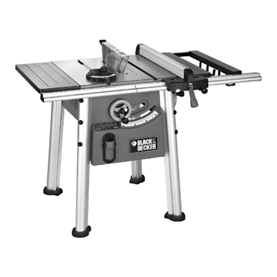
Cat #BT2500
B B
T T
2 2
5 5
0 0
0 0
B B
T T
2 2
5 5
0 0
0 0
INSTRUCTION MANUAL
INSTRUCTIVO DE OPERACIÓN, CENTROS DE SERVICIO Y PÓLIZA
DE GARANTIA. ADVERTENCIA: LEASE ESTE INSTRUCTIVO ANTES
DE USAR EL PRODUCTO. SI TIENE DUDAS, POR FAVOR LLAME.
Form # 606404-00
1 1
0 0
' '
' '
T T
A A
B B
1 1
0 0
' '
' '
T T
A A
B B
B E F O R E R E T U R N I N G T H I S
1-800-54-HOW-TO (544-6986)
CALL 1-800-54-HOW-TO (544-6986)
BEFORE YOU CALL, HAVE THE FOLLOWING INFORMATION
AVAILABLE, CATALOG No., TYPE No., AND DATE CODE (e.g.
200130CTM). IN MOST CASES, A BLACK & DECKER REPRE-
SENTATIVE CAN RESOLVE YOUR PROBLEM OVER THE
PHONE. IF YOU HAVE A SUGGESTION OR COMMENT, GIVE
US A CALL. YOUR FEEDBACK IS VITAL TO BLACK & DECKER.
(JUN-01-1)
L L
E E
S S
A A
W W
L L
E E
S S
A A
W W
P R O D U C T F O R A N Y
R E A S O N P L E A S E
IF YOU SHOULD EXPERIENCE A PROBLEM
WITH YOUR BLACK & DECKER PRODUCT,
Copyright © 2001 Black & Decker
C A L L
Printed in China
Publicité
Chapitres
Table des Matières

Manuels Connexes pour Black & Decker BT2500


Sommaire des Matières pour Black & Decker BT2500
- Page 1 INSTRUCTIVO DE OPERACIÓN, CENTROS DE SERVICIO Y PÓLIZA DE GARANTIA. ADVERTENCIA: LEASE ESTE INSTRUCTIVO ANTES MANUAL DE INSTRUCCIONES DE USAR EL PRODUCTO. SI TIENE DUDAS, POR FAVOR LLAME. Cat #BT2500 Form # 606404-00 (JUN-01-1) Copyright © 2001 Black & Decker...
-
Page 2: Table Des Matières
TABLE OF CONTENTS • Table Of Contents..............2 Adjustment of Miter Gauge............10 • Rules For Safe Operation............3 Rip Fence Operation And Adjustment ........10 • • Electrical ..................3 Micro Knob Adjustment............10 • • Important Safety Instructions ............3 Replacing The Blade ..............10 • •... -
Page 3: Grounding Instructions
GROUNDED WARNING: FOR YOUR OWN SAFETY, READ INSTRUCTION MANUAL OUTLET GROUNDING BEFORE OPERATING SAW MEANS • ALWAYS WEAR EYE PROTECTION • DO NOT WEAR GLOVES, NECKTIES, JEWELRY OR LOOSE CLOTHING • CONTAIN LONG HAIR • KEEP HANDS AND FINGERS OUT OF THE SAW BLADE PATH — USE EXTRA CAU- GROUNDING PIN ADAPTER GROUNDING PIN... -
Page 4: Saw Blade Guard And Spreader
of parts, mounting, and any other conditions that may affect its operation. A guard or other part KICKBACKS - HOW TO AVOID THEM AND PROTECT that is damaged should be properly repaired or replaced. YOURSELF FROM POSSIBLE INJURY: • DIRECTION OF FEED. Feed work into a blade or cutter against the direction of rotation of the blade or cutter only. -
Page 5: Necessary Hardware
Contents There are five hardware bags which contain all the necessary nuts, bolts and washers to 4 - Hex nuts assemble the components included with the BT2500. The bags are organized as follows: 4 - Lockwashers 2 - Cap screws... -
Page 6: Unpacking
UNPACKING & ASSEMBLY- FIG.A Carefully unpack the table saw and all loose items from the carton. Examine all parts to make sure that parts have not been dam- aged during shipping. If any parts are missing or damaged, contact your dealer to replace them before attempting to assemble the tool.Illustrated below are all the loose items (excluding the hardware bags) packed with the saw. -
Page 7: Tools Included
Assembly for BT2500 STEP 4. Clean the table top. Before proceeding with the assembly of your saw, it is recommended that you clean the table- PLEASE READ ENTIRE ASSEMBLY SECTION top to remove the rust preventive coating. Clean the top with mineral spirits or denatured alco- BEFORE PROCEEDING. - Page 8 STEP 8. Aligning and leveling the front rail assembly (Figures 9,10) Loosen the lock knob in the center of the front hand crank and turn the crank handle clock- wise to raise the blade so that it is approximately two inches above the tabletop. Thread the orange rip fence locking handle (part C) into the front of the rip fence (part B).
-
Page 9: Adjustments
guard clamp nuts (D) which changes the location where the spreader mounts. Make sure STEP 11. Attaching rear rails (Figures 16,17) the spreader is centered and parallel to the blade by lining up the parts with a straightedge. From the rear of the saw attach the longer rear rail to the left side of the tabletop (Figure Also make sure there is some clearance between the spreader and the blade and that the 16) using three capscrews with lockwashers. -
Page 10: Bevel Pointer Adjustment
STEP 2. Adjust the bevel stops The procedure for making the other adjustment, “Fence Clamping Tension,” is performed as follows: CAUTION: Turn off and unplug saw. If you are experiencing problems with the fence slipping: 1. Loosen the bevel lock handle and turn the bevel angle handwheel clockwise until it stops. 1. -
Page 11: Leveling The Saw
6. NOTE: Different types of blades make different kerfs (width of cuts). Therefore, it is nec- 5. Never stack blades on top of one another to store. Place material such as cardboard essary to check adjustment of rip fence pointer and blade guard splitter when changing between them to keep the blades from coming in contact with one another. -
Page 12: Bevel Ripping
MITERING BEVEL RIPPING This operation is the same as crosscutting except the miter gauge is locked at an angle other This operation is the same as ripping except the bevel angle is set to an angle other than zero than 0°. Hold the workpiece FIRMLY against the miter gauge and feed the workpiece slowly degrees. -
Page 13: Maintenance
Maintenance ACCESSORIES Recommended accessories for use with your tool are available from your local dealer or Use only mild soap and damp cloth to clean the tool. Never let any liquid get inside the tool; authorized service center. If you need assistance regarding accessories, please call: never immerse any part of the tool into a liquid. - Page 15 ’ ’ É É ’ ’ É É GUIDE D’UTILISATION AVA N T D E R E T O U R N E R C E P R O D U I T P O U R Q U E L Q U E R A I S O N Q U E C E S O I T, C O M - P O S E Z L E 1 8 0 0 5 4 4 - 6 9 8 6 .
- Page 16 TABLE DES MATIÈRES • Table des matières ..............16 Réglage de la jauge à onglets ..........24 • Consignes de sécurité ............17 Fonctionnement et réglage du guide de refend ....24 • • Électricitél ................17 Bouton de micro-réglages ............25 • • Consignes de sécurité importantes ........17 Remplacement de la lame ............25 •...
-
Page 17: Directives Concernant La Mise À La Terre
IMPORTANTES CONSIGNES DE SÉCURITÉ AVERTISSEMENT : POUR ASSURER LA SÉCURITÉ DE L’UTILISATEUR, LIRE LE GUIDE D’UTILISATION AVANT DE SE SERVIR DE LA SCIE. • GARDER LES DISPOSITIFS DE PROTECTION EN PLACE et en bon état de fonction nement. • TOUJOURS PORTER DES LUNETTES DE SÉCURITÉ. •... -
Page 18: Consignes De Sécurité Additionnelles Concernant Les Scies D'établi
• NE JAMAIS METTRE LES PIEDS SUR L’OUTIL; si l’outil se renverse ou est accidentelle- TERMES : ment mis en marche, il pourrait entraîner des blessures graves. Les termes suivants seront utilisés tout au long du présent guide; il est donc important •... -
Page 19: Conserver Les Présentes Directives À Titre De Référence
6 – Vis d’assemblage avec ron- Cinq sacs de ferrures sont fournis; ils contiennent les écrous, les boulons et les rondelles néces- delles de blocage saires pour assembler les composants fournis avec la scie d’établi BT2500. Les ferrures sont réparties comme suit : CLÉS Contenu : 2 –... -
Page 20: Déballage
DÉBALLAGE ET ASSEMBLAGE - FIGURE A Déballer soigneusement la scie d’établi et la retirer ainsi que tous les composants qui se trouvent dans la boîte. Examiner chaque pièce pour s’assurer qu’aucun dommage n’a été causé durant le transport. Si une pièce est endommagée ou manquante, communiquer avec le déposi- taire concerné... -
Page 21: Outils Fournis
ÉTAPE 5. Assemblage de la roue (figures 4 et 5) Roue de réglage d’angle de biseau (située du côté droit de la scie). Fixer le manchon (la BT2500 pièce K emballée dans du Styrofoam) à la tige qui dépasse du côté de la scie d’établi, tel qu’il- lustré... -
Page 22: Alignement Et Mise À Niveau Du Montant Avant
ÉTAPE 9. Fixation des rallonges droite et gauche du plateau (figures 11, 12 et 13) Insérer un boulon à tête carrée fournie dans le sac des pièces de la rallonge du plateau illustré à gauche dans l’ouverture du canal située à l’extrémité du montant avant (figure 11). -
Page 23: Fixation Des Montants Arrière
ÉTAPE 13. Installation de l’ensemble protège-lame / barre d’écartement (figures 20, 21, ÉTAPE 11. Fixation des montants arrière (figures 16 et 17) 22 et 23) À partir de l’arrière de la scie, fixer le plus long montant arrière au côté gauche de la surface Enlever la plaque amovible en suivant l’illustration de la figure 20. -
Page 24: Réglages
ÉTAPE 3. Réglage de l’indicateur du biseau Si l’indicateur du biseau n’affiche pas 0 º, lorsque la lame est placée à 90 º par rapport à la surface du plateau, desserrer la vis de l’indicateur au moyen d’un tournevis Phillips. (On peut accéder à... -
Page 25: Bouton De Micro-Réglages
tenir la section avant du guide contre le montant de la surface du plateau lorsqu’on serre le levier de verrouillage à cames. Le serrer fermement afin d’empêcher le guide de se déplac- er durant le sciage. CONSEIL PRATIQUE : régler l’indicateur d’échelle de coupe en long chaque fois qu’on installe une lame plus épaisse ou plus mince. -
Page 26: Fonctionnement
5. Ne jamais ranger les lames en les empilant les unes sur les autres. Placer un matériau 6. Ne JAMAIS tenter de tirer la pièce vers soi lorsque la lame tourne. Mettre plutôt l’inter- rupteur hors tension, attendre que la lame s’arrête complètement, soulever les linguets anti- comme un carton entre chaque lame pour empêcher tout contact entre elles. -
Page 27: Coupe Transversale Biseautée
MISE EN GARDE : toujours vérifier le jeu de la lame à rainer avant de brancher la scie dans une source d’alimentation électrique. Une fois la coupe à rainer terminée, s’assurer de remettre le protège-lame en place et de vérifier de nouveau les réglages. AVERTISSEMENT : avant de brancher la scie d’établi à... -
Page 28: Accessoires
Cette garantie ne s’applique pas aux accessoires. Elle confère des droits légaux particuliers à l’acheteur, mais celui-ci pourrait aussi bénéficier d’autres droits variant d’un territoire à l’autre. Toute question doit être adressée au gérant du centre Black & Decker le plus près. Ce pro- duit n’est pas destiné... - Page 30 ” ” ” ” MANUAL DE INSTRUCCIONES A N T E S D E D E V O LV E R E S T E P R O D U C T O P O R C U A L Q U I E R M O T I V O , FAV O R L L A M A R A L 1 - 8 0 0 - 5 4 - H O W - T O ( 5 4 4 - 6 9 8 6 DE TENER ALGÚN PROBLEMA CON SU PRODUC-...
-
Page 31: Indice
INDICE • Indice ..................31 Ajuste del apuntador de biselado ..........39 • Reglas para una operación segura ..........32 Ajuste del cartabón de ingletes ..........39 • Electricidad ................32 Guía longitudinal – Operación y ajustes ......39 • Consignes de sécurité importantes ........32 • Perilla de microajustes ............39 •... -
Page 32: Instrucciones Para La Conexión A Tierra
ADVERTENCIA: PARA SU PROPIA SEGURIDAD, LEA EL MAN- • ASEGURE SU TALLER A PRUEBA DE NIÑOS con candados, interruptores maestros, o UAL DE INSTRUCCIONES ANTES DE OPERAR LA SIERRA quitando las llaves de arranque. • NO FUERCE LA HERRAMIENTA. Esto le permitirá ejecutar el trabajo mejor, de manera •... -
Page 33: Protegehoja Y Separador
• DIRECCIÓN DEL AVANCE. Avance la pieza de corte hacia la hoja o cortador solamente avance. Durante el rebote, la pieza de corte podría ser lanzada de vuelta al operador. También en la dirección opuesta a la hoja o cortador. puede arrastrar la mano del operador de regreso a la hoja si la mano de éste se encuentra en •... - Page 34 EXTENSIÓN Hay cinco bolsas de herrajes que contienen todas las tuercas, pernos y arandelas necesarias para ContenIdo ensamblar los componentes incluidos en la BT2500. Las bolsas están organizadas como sigue: 4 – Tuercas hexagonales 4 – Arandelas de seguridad BOLSA DE LLAVES 2 –...
- Page 35 DESEMPAQUE Y ENSAMBLADO - FIG.A Desempaque cuidadosamente la sierra de mesa y todas las piezas sueltas. Examine todas las partes para verificar que ninguna se haya dañado durante el transporte. De haber piezas dañadas o faltantes, contacte a su distribuidor para que sean reemplazadas antes de ensam- blar la herramienta.
-
Page 36: Herramientas Incluidas
Ensamblado de la BT2500 PASO 4. Limpie el tope de la mesa. Antes de proceder con el ensamblado de la sierra, se recomienda que usted limpie el tope POR FAVOR LEA TODA LA SECCION DE ENSAMBLADO ANTES de la mesa para quitar la capa de prevención de óxido. Limpie el tope con alcoholes min- DE PROCEDER. - Page 37 PASO 8. Alineado y nivelación del ensamblado del riel delantero (Figuras 9,10) Afloje la perilla de seguridad del centro de la manivela delantera y gire la manivela en senti- do horario para elevar la hoja para que quede a aproximadamente dos pulgadas encima del tope de la mesa.
- Page 38 PASO 11. Unión de los rieles traseros (Figuras 16,17) PASO 13. Instalación del conjunto de protegehoja y separador (Figuras 20,21,22,23) Desde la parte posterior de la sierra, una el riel trasero más largo con el lado izquierdo del Quite la placa de garganta como lo ilustra la Figura 20. Baje la hoja a la altura del tope de la tope de mesa (Figura 16) utilizando tres tornillos de casquete con arandelas de seguridad.
-
Page 39: Verificación De La Placa De Garganta
PASO 1. Verificación de la placa de garganta PASO 5. Guía longitudinal – Operación y ajustes (Figura 25) ATENCIÓN:La guía longitudinal debe alinearse en paralelo con la hoja para minimizar el Para cambiar la altura de la placa de garganta, afloje el tornillo de cabeza phillips ubicado en peligro de rebote. -
Page 40: Reemplazo De La Hoja De Corte
REEMPLAZO DE LA HOJA DE CORTE (FIGURA 26). ATENCIÓN : Apague y desconecte la sierra. 1. Fije el árbol de la hoja de sierra a aproximadamente una pulgada por encima del tope de mesa girando el volante de ajuste de altura de la hoja (en la parte delantera de la sierra) en sentido antihorario. -
Page 41: Corte Longitudinal
4. En cortes al través, la perilla del cartabón de ingletes está apretada. 5. El operador tiene puestos los anteojos de seguridad. 6. El protegehoja está correctamente montado y los dientes anti-rebote funcionan. La falta de adhesión a estas rutinas de seguridad puede aumentar en gran cuantía la probabilidad de sufrir lesiones. -
Page 42: Aserrado En Inglete Compuesto
reparación, mantenimiento y ajuste debe efectuarse en los centros de servicio autorizados u otras organizaciones de servicio calificados, utilizando siempre repuestos idénticos. CUIDADO DEL TOPE DE MESA Proteja su inversión. Mantenga la sierra de mesa limpia. De notar señales de óxido, frote las áreas con lana de acero, limpie con alcoholes minerales o de quemar y aplique cera en pasta. -
Page 43: Accesorios
ACCESORIOS Encontrará accesorios recomendados para la herramienta en los centros de venta de productos Black & Decker. ADVERTENCIA:Puede ser peligroso usar cualquier accesorio no recomendado. PARA REPARACION Y SERVICIO DE SUS HERRAMIENTAS ELECTRICAS FAVOR DE DIRIGIRSE AL CENTRO DE SERVICIO MAS CERCANO CULIACAN Av.