Table des Matières
Publicité
Liens rapides
www.grepool.com
790096
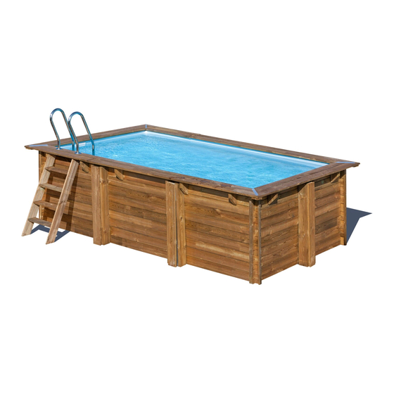
4,27 x 2,77 x H 1,19m
KPBRC420
4,20 x 2,20 x H 1,19m
KPBRC620
6,18 x 3,20 x H 1,30m
NON-CONTRACTUAL PHOTOS AND PICTURES. FOTOS E IMÁGENES NO CONTRACTUALES. PHOTOS ET IMAGES NON CONTRACTUELLES. PHOTOS UND BILDER SIND NICHT VERTRAGLICH.
LA FOTOGRAFIA O IL DISEGNO È SOLO A SCOPO ILLUSTRATIVO ED INFORMATIVO. FOTO'S EN AFBEELDINGEN HEBBEN GEEN CONTRACTUELE WAARDE. FOTOS E IMAGENS NAO CONTRATADA.
Instruction Manual
EN
Take the reference number of your pool into
account when you do the assembly
Manual de Instrucciones
ES
Tenga en cuenta la referencia y las medidas de
su piscina a la hora de realizar el montaje
Notice de Montage
FR
Considérez la référence et les mesures de
votre piscine avant de procéder au montage
Bedienungsanleitung
DE
Bitte beachten Sie die Referenz und die
Masse Ihres Schwimmbads, wenn Sie die
Montage ausführen
MAR
BE
LLA
ROSE
MARY
MARY
MAN
MAN
MAN
GO
Manuale delle instruzioni
IT
Tener presente il riferimento della piscina al
momento del montaggio
Handleiding met instructies
NL
Op het moment van monteren dient u
rekening te houden met de referentie en de
afmetingen van uw zwembad
Manual de instruções
PT
Tenha em conta a referência da piscina momento
de realizar a montagem
Publicité
Table des Matières

Manuels Connexes pour GRE MARBELLA


Sommaire des Matières pour GRE MARBELLA
- Page 1 Instruction Manual Manuale delle instruzioni Take the reference number of your pool into Tener presente il riferimento della piscina al account when you do the assembly momento del montaggio Manual de Instrucciones Handleiding met instructies Tenga en cuenta la referencia y las medidas de Op het moment van monteren dient u rekening te houden met de referentie en de su piscina a la hora de realizar el montaje...
-
Page 2: Table Des Matières
Ref. 790096 SUMMARY 4,27 x 2,77 x H 1,19m ÍNDICE SOMMAIRE INHALTSVERZEICHNIS Ref. KPBRC420 RIASSUNTO 4,20 x 2,20 x H 1,19m SAMENVATTING RESUMO Ref. KPBRC620 6,18 x 3,20 x H 1,30m Important/ Importante/ Important/ Wichtig/ Importante/ Belangrijk/ Importante Guarantee/ Garantía/ Garantie/ Garantie/ Garanzia/ Garantie/ Garantia Learn about the wood/ Conozca la madera/ Mieux connîatre le bois/ Das Holz besser kennenlernen/ Conosci il legno/ Wat u moet weten over hout/ Conheça a madeira Installation drawing / Plano de instalación / Plan d´implantation / Aufstellplan / Piano di installazione /... - Page 3 Fixing of the skimmer joint / Fijación de la junta skimmer / Fixation du joint de skimmer / Befestigung der Dichtung des Skimmers / Fissaggio del giunto dello skimmer / Vastzetten van de skimmerverbinding / Fixação da junta do skimmer Installation of the liner hooking profile/ Colocación de los perfiles de enganche del liner/ Positionne- ment des baguettes d´accroche de liner/ Positionierung der Einhängeprofile der Poolfolie/ Posizion- amento dei profili di aggancio del liner/ Plaatsing van de klemprofielen voor inhangen van de liner/...
-
Page 4: Important/ Importante/ Important/ Wichtig/ Importante/ Belangrijk/ Importante
IMPORTANT IMPORTANTE IMPORTANT WICHTIG IMPORTANTE BELANGRIJK IMPORTANTE COMPULSORY·OBLIGATORIO·IMPÉRATIF·OBLIGATORISCH ·OBBLIGATORIO ·VERPLICHT ·OBRIGATÓRIO It is mandatory to keep it in order to use the warranty Obligatorio conservarlo para poder hacer uso de la garantía Il est obligatoire de le conserver pour pouvoir valider la garantie Um die Garantie in Anspruch zu nehmen, muss sie aufbewahrt werden Obbligatorio conservarlo per poter usufruire della garanzia U bent verplicht dit te bewaren om later gebruik te kunnen maken van de garantie... - Page 5 The diagonal dimensions of the pool SHOULD BE verified. This is necessary to avoid problems later. Revise them several times until obtaining the dimensions indicated on the drawings. Es IMPRESCINDIBLE verificar las medidas de las diagonales de las piscinas. De esta manera se evitarán problemas posteriormente. Revisar esto varias veces hasta obtener las medidas indicadas en los planos.
- Page 6 In caso di rotture e/o deformazioni del legno, effettuare l’inventario completo dello stato dei vari pezzi prima di farne richiesta al servizio post-vendita. In questo modo, verranno tutti inclusi nella medesima spedizione Per il montaggio, la linguetta presente sul listone deve essere sempre rivolta verso l’alto (per piscine con sistema a incastro). (A) Nella prima fila di listoni (la base della piscina) è...
- Page 7 To install the blocks (pieces of wood that support the beaches), pay attention to the pool drawing. It is important that these are screwed in the exact position indicated on the drawing. Do not over-tighten the screws to avoid splintering the wood. It is recommended to sand the areas with splinters to eliminate the risk of cutting.
- Page 8 En su objetivo constante de mejorar sus productos, Manufacturas Gre se reserva el derecho a modificar en cualquier momento y sin previo aviso las características, los detalles técnicos, los equipamientos estandarizados y las opciones de sus productos.
- Page 9 ATTENZIONE Leggere attentamente queste informazioni e e conservarle per farvi riferimento in futuro Congratulazioni per la tua scelta. Il modello che hai scelto è stato progettato in modo particolare per una installazione semplice e rapida, ma per un uso corretto della piscina sono necessarie alcune precauzioni. Prima di procedere con l’installazione e il montaggio della tua piscina, informati su quanto previsto dal piano regolatore.
-
Page 10: Guarantee/ Garantía/ Garantie/ Garantie/ Garanzia/ Garantie/ Garantia
GUARANTEE Keep your manual with the serial number and the purchase justification (payment receipt) for any type of reclamation. Any reclamation against guarantee should be made by an You should keep the label with the serial number of the liner online declaration, via the www.grepool.com/en/after-sales, that is on the product and on its packaging. - Page 11 PROLOGUE STORAGE PRECAUTIONS - Pool alarm - Pool cover While the pool is disassembled, it is sensitive to variations of - Pool hut temperature and humidity. Therefore, certain precautions should INSTALLATION SUGGESTION be taken for storage. When you receive the packets, store the pieces of wood in horizontal position on a flat surface, shielding them from humidity The land should be prepared as indicated in the «installation»...
-
Page 12: Safety Instructions
PROLOGUE SAFETY INSTRUCTIONS The filter kit (filter + pump) should be installed at least 3.5 metres from the pool to avoid the risk of electrocution. There should be a special differential electricity protection device for pools with electric filter pumps, according to the regulation. Never leave children without surveillance near the pool. - Page 13 STANDARD SWIMMINGPOOLS 2015 WARNING: Every electrical appliance fed in 220 V, has to be located at least at 3,50 m from the edge of the pool. The equipment should be connected to a voltage, with earth connection, protected by a residual current device (RCD) having a rated residual operating current not exceeding 30 mA.
- Page 14 (Previa justificación y prueba de compra) Si después del peritaje no se detecta ninguna anomalía o disfunción, la sociedad Manufacturas Gre se reserva el derecho de facturar los costes de portes y otros diversos al cliente. • Portes de ENVÍO por cargo del cliente.
-
Page 15: Antes Del Montaje
ANTES DEL MONTAJE PRECAUCIONES DE ALMACENAMIENTO elemento de protección normalizado, como: Mientras la piscina se encuentra desmontada, es sensible a - Barrera de protección las variaciones de temperatura y de humedad. Por lo tanto, es - Alarma de piscina necesario tomar ciertas precauciones de almacenamiento. - Cubierta de piscina Cuando reciba los paquetes, guarde las piezas de madera en - Refugio de piscina... -
Page 16: Instrucciones De Seguridad
ANTES DEL MONTAJE INSTRUCCIONES DE SEGURIDAD Es obligatorio colocar el kit de filtración (filtro + bomba) a una distancia mínima de 3,5 metros de la piscina para evitar el riesgo de descarga eléctrica. Es obligatorio prever la instalación de un dispositivo de protección diferencial especial para piscinas en la alimentación eléctrica de la bomba, conforme a la normativa. - Page 17 STANDARD SWIMMINGPOOLS 2015 ATENCIÓN: Todo aparato alimentado en 220 V, debe situarse por lo menos a 3,50 m del borde de la piscina. El equipo se debe conectar a una toma de corriente, con conexión a tierra, protegida con un interruptor diferencial (RCD) con una corriente de funcionamiento residual asignada que no exceda de 30 mA.
-
Page 18: Garantie
GARANTIE Pour toute réclamation/SAV, conservez votre notice avec avec les Nº de série (palette bois + liner) ainsi que votre preuve d’achat (ticket de caisse). Toute demande de garantie devra faire l’objet d’une déclaration Il est impératif de conserver l’étiquette du numéro de série en ligne sur le site: du liner présent sur le produit et son emballage. -
Page 19: Avant-Propos
AVANT-PROPOS PRECAUTIONS DE STOCKAGE n°2003-9 du 3 janvier 2003 relative à la sécurité des piscines, et le décret n°2003-1389 du 31 décembre 2003 relatif à la sécurité Tant que la piscine n’est pas assemblée, elle est sensible aux des piscines vous imposent de sécuriser l’accès au bassin par au variations de températures moins un élément de protection normalisé... -
Page 20: Consignes De Securite
AVANT-PROPOS CONSIGNES DE SECURITE Il est impératif de placer votre kit de filtration (filtre + pompe) à au moins 3,5 m. du bassin afin d’éviter tout risque de choc électrique. Il est impératif de prévoir sur l’alimentation électrique de la pompe un dispositif de protection différentiel spécial piscines, conforme aux normes. Ne jamais laisser les enfants sans surveillance à... - Page 21 STANDARD SWIMMINGPOOLS 2015 ATTENTION: Tout appareil électrique alimenté en 220 V doit être situé au moins à 3,50 m du bord du bassin. L’appareil doit être branché sur une prise de courant avec prise de terre, protégé par un interrupteur différentiel (RCD) avec un courant de fonctionnement résiduel assigné...
- Page 22 GARANTIE Für etwaige Beanstandungen oder Kundendienst bewahren Sie Ihr Handbuch mit der Seriennummer sowie dem Kaufbeleg (Quittung) auf. Jegliche Garantieansprüche müssen online auf der Webseite klebt. Für etwaige Anträge auf Übernahme der Garantie ist www.grepool.com/de/kundenservice, zusammen mit dem eine Probe des Liners erforderlich. Kaufbeleg, geltend gemacht werden.
- Page 23 EINLEITUNG VORKEHRUNGEN FÜR DIE LAGERUNG Zugang zum Becken durch eines der folgenden standardisierten Elemente geschützt sein muss: Solange der Pool noch nicht zusammengebaut ist, reagiert er - Schutzabsperrung empfindlich auf Feuchtigkeit und Temperaturschwankungen. - Poolalarm Folglich müssen Lagerung bestimmte - Abdeckung des Pools Vorsichtsmaßnahmen treffen.
-
Page 24: Sicherheitshinweise
EINLEITUNG SICHERHEITSHINWEISE Es ist erforderlich, den Filtrationsbausatz (Filter + Pumpe) in einem Mindestabstand von 3,5 Metern zum Pool zu platzieren, um das Risiko eines Stromschlags zu vermeiden. Laut Norm ist es vorgeschrieben, die Installation einer speziellen Differenzialschutzvorrichtung für Pools bei der Stromversorgung der Pumpe einzuplanen. - Page 25 BEI PROBLEMEN KÖNNEN SIE SICH MIT UNS UNTER TO THE NORM DER FOLGENDEN DEUTSCHEN TELEFONNUMMER IN VERBINDUNG SETZEN: kundenservice@gre.es www.grepool.com/de TO THE NORM Wenn Sie Ihren Pool aufgestellt und alle Bauteile zusammengebaut haben, wären wir Ihnen dankbar, wenn Sie die Verpackungen sortieren und dem Recycling zuführen.
- Page 26 GARANZIA In caso di reclami o per assistenza post vendita, conservare il manuale con il numero di serie insieme alla prova di acquisto (scontrino). Qualsiasi richiesta di garanzia deve essere inoltrata on line, liner presente nel prodotto e nel suo imballaggio. Per qualsiasi tramite la pagina web www.grepool.com/it/post-vendita, eventuale domanda di assunzione di garanzia, sarà...
-
Page 27: Prima Dell'installazione
INTRODUZIONE PRECAUZIONI PER LO STOCCAGGIO standard per l’accesso alla vasca, come ad esempio: Quando la piscina è smontata, è sensibile alle variazioni di − Barriera di protezione temperatura e di umidità. È quindi necessario adottare alcune − Allarme della piscina precauzioni per lo stoccaggio. -
Page 28: Istruzioni Di Sicurezza
INTRODUZIONE ISTRUZIONI DI SICUREZZA È obbligatorio collocare il kit di filtrazione (filtro + pompa) a una distanza minima di 3,5 metri dalla piscina per evitare il rischio di scariche elettriche. È obbligatorio prevedere l’installazione di un dispositivo di protezione differenziale speciale per la piscina nell’alimentazione elettrica della pompa, in conformità... - Page 29 STANDARD SWIMMINGPOOLS 2015 ATTENZIONE: Ogni apparecchio alimentato a 220 V, deve essere situato ad almeno 3,50 m dal bordo della piscina. L’attrezzatura va collegata ad una presa di tensione di corrente alterna, con una connessione a terra, protetta con un interruttore differenziali (RCD) con una corrente di funzionamento residuale assegnata che non ecceda i 30 mA.
- Page 30 GARANTIE Voor iedere claim of after-sales service, uw handleiding met het serienummer tezamen met het aankoopbewijs (factuur, kassabon) gereedhouden. Elke aanspraak op garantie zal onderwerp zijn van een online vervorming van de liner indien deze meer dan 24 uur zonder water declaratie, via de website www.grepool.com/en/after-sales, heeft gestaan (maak het zwembad nooit helemaal leeg).
- Page 31 WOORWOORD VOORSCHRIFTEN VOOR OPSLAG 1389 van 31 december 2003 met betrekking tot de veiligheid van zwembaden, dat de toegang tot het bassin door tenminste een Zolang het zwembad niet is gemonteerd, is het gevoelig voor standaard beschermelement moet worden beveiligd, zoals: temperatuurschommelingen en vocht.
-
Page 32: Veiligheidsinstructies
WOORWOORD VEILIGHEIDSINSTRUCTIES Het is verplicht om de filterkit (filter + pomp) op een minimum afstand van 3,5 meter van het zwembad te plaatsen om het risico van elektrische ontlading te vermijden. Het is verplicht de elektrische voeding van de pomp te voorzien van een lekkagebeveiliging speciaal voor zwembaden, in overeenstemming met de voorschriften. - Page 33 STANDARD SWIMMINGPOOLS 2015 BELANGRIJK: Alle apparaten die gevoed worden met 220 V, dienen zich op z’n minst op een afstand van 3,50 meter van de rand het zwembad te bevinden. Het toestel moet aangesloten op een geaard netwerk met een wisselstroomspanning van 230 V en 50 HZ, en moet beschermd zijn door een differentieelschakelaar (RCD) met een residuele differentieelstroom van niet meer dan 30 mA.
- Page 34 GARANTIA Para qualquer reclamação ou serviço pós-venda, conserve o seu manual com o número de série, juntamente com o comprovativo de compra (ticket de caixa). Qualquer reclamação de garantia deverá ser objeto de uma por completo). declaração online, no site www.grepool.com/post-venta, É...
- Page 35 PRELIMINAR PRECAUÇÕES DE ARMAZENAMENTO de dezembro de 2003, relativo à segurança das piscinas, exigem proteger o acesso ao tanque através de pelo menos um elemento Enquanto a piscina se encontra desmontada, é sensível às de proteção normalizado, como: variações de temperatura e de humidade. Portanto, é necessário - Barreira de proteção tomar certas precauções de armazenamento.
-
Page 36: Instruções De Segurança
PRELIMINAR INSTRUÇÕES DE SEGURANÇA É obrigatório colocar o kit de filtração (filtro + bomba) a uma distância mínima de 3,5 metros da piscina para evitar o risco de descarga elétrica. É obrigatório prever a instalação de um dispositivo de proteção diferencial especial para piscinas na alimentação elétrica da bomba, nos termos do regulamento. - Page 37 STANDARD SWIMMINGPOOLS 2015 ATENÇÃO: Qualquer aparelho eléctrico alimentado com 220 V, deve estra situado pelo menos a 3,50 m do borde da piscina. O aparelho deve ser ligado a uma tomada de corrente alterna, com ligação à terra, protegida com um interruptor diferencial (RCD) com uma corrente de funcionamento residual que não exceda os 30 mA.
-
Page 38: Learn About The Wood/ Conozca La Madera/ Mieux Connîatre Le Bois/ Das Holz Besser Kennenlernen
LEARN ABOUT THE WOOD WOOD: A LIVING MATERIAL CONOZCA LA MADERA Wood is a natural product, the fissures visible on the edges of the wood are completely normal and do not modify the MIEUX CONNÎATRE LE BOIS resistance characteristics of the same. Wood is always a malleable material (from 3% to 4% of dimensional variations) with humidity and temperature DAS HOLZ BESSER KENNENLERNEN... - Page 39 Cracks/Grietas/Fente/Risse/ Resin/Resina/Résine/Harz/ Nerves and long knots Retention of sterilization products Differences in shades of colour Crepe/ Barsten/Fendas Resina/ Hars/Resinas Nervios y nudos alargados Retención de productos de esterilización Diferencias de tonalidad Nervures et noeuds longs Rétention de produits détuve Différences de teinte Geäder und lange knoten Rückstände von Sterilisationsprodukten Unterschiede im Farbton...
-
Page 40: Installation Drawing / Plano De Instalación / Plan D´implantation / Aufstellplan / Piano Di Installazione
Ref. 790096 INSTALLATION DRAWING PLANO DE INSTALACIÓN PLAN D´IMPLANTATION Dimensions in mm Cotas en mm AUFSTELLPLAN Cotations en mm Höhenangaben in mm PIANO DI INSTALLAZIONE Livello in mm Afmetingen in mm Cotas em mm TIPS VOOR DE VEILIGHEID PLANO DE INSTALAÇÃO REF/RÉF DENOMINATION/DENOMINACIÓN CTD/QTÉ/ANZ... - Page 41 Ref. 790096 Dimensions in mm Cotas en mm Cotations en mm Höhenangaben in mm Livello in mm Afmetingen in mm Cotas em mm 4000 3884 3792 You should respect all these dimensions Per sistemare alla perfezione il liner e to perfectly adjust the liner and the i bordi è...
- Page 42 Ref. KPBRC420 INSTALLATION DRAWING PLANO DE INSTALACIÓN PLAN D´IMPLANTATION Dimensions in mm AUFSTELLPLAN Cotas en mm Cotations en mm Höhenangaben in mm PIANO DI INSTALLAZIONE Livello in mm Afmetingen in mm TIPS VOOR DE VEILIGHEID Cotas em mm PLANO DE INSTALAÇÃO REF/RÉF DENOMINATION/DENOMINACIÓN CTD/QTÉ/ANZ...
- Page 43 Ref. KPBRC420 Dimensions in mm Cotas en mm Cotations en mm Höhenangaben in mm Livello in mm Afmetingen in mm Cotas em mm 4000 3726 3818 You should respect all these dimensions Per sistemare alla perfezione il liner e to perfectly adjust the liner and the i bordi è...
- Page 44 Ref. KPBRC620 INSTALLATION DRAWING PLANO DE INSTALACIÓN PLAN D´IMPLANTATION Dimensions in mm AUFSTELLPLAN Cotas en mm Cotations en mm Höhenangaben in mm PIANO DI INSTALLAZIONE Livello in mm Afmetingen in mm TIPS VOOR DE VEILIGHEID Cotas em mm PLANO DE INSTALAÇÃO REF/RÉF DENOMINATION/DENOMINACIÓN CTD/QTÉ/ANZ...
- Page 45 Ref. KPBRC620 Dimensions in mm Cotas en mm Cotations en mm Höhenangaben in mm Livello in mm Afmetingen in mm Cotas em mm 4000 2000 5696 5788 You should respect all these dimensions Per sistemare alla perfezione il liner e to perfectly adjust the liner and the i bordi è...
-
Page 46: Previsions / Previsiones / A Prévoir / Vorausplanung / Precauzioni / Rekening Houden Met / Previsões
PREVISIONS PREVISIONES 3,50 m min. A PRÉVOIR VORAUSPLANUNG FILTER GROUP GRUPO DE FILTRACIÓN GROUPE DE FILTRATION FILTERANLAGE The filter group and especially El grupo defiltración y en Le groupe de filtration Das Filteranlage und the electric pump should especial la bomba eléctrica et notamment la pompe besonders die elektrische necessarily be located at a... - Page 47 PRECAUZIONI REKENING HOUDEN MET 3,50 m min. PREVISÕES SISTEMA DI FILTRAZIONE FILTERGROEP GRUPO DE FILTRAÇÃO Il sistema di filtrazione e in De filtergroep en in het O grupo de filtração, e em particolare la pompa elettrica bijzonder de elektrische pomp especial a bomba elétrica della piscina devono essere van het zwembad moeten...
-
Page 48: Components/ Componentes/ Elements/ Bestandteile Componenti/ Onderdelen/ Componentes
· COMPONENTS · COMPONENTES · ELEMENTS · BESTANDTEILE COMPONENTI · ONDERDELEN · COMPONENTES KPBRC420 KPBRC620 790096 PV1335 PV1185 PEAO WOOD WOOD KIT2V1185 KIT4PEAO2 KIT2V1335AA SCREWS SCREWS LINER STAINLESS LINER KITALETA STEEL LADER MONOBLOCK STAINLESS FLOOR STEEL LADER TAPESTRY HOSE SKIMMER PG144O KIT2G1440 MONOBLOCK... - Page 49 GROUND LAYOUT - TRAZADO EN EL TERRENO - TRACÉ AU SOL 790096 KPBRC420 KPBRC620 5200 mm 7000 mm 5200mm 70 cm 70 cm 70 cm 70 cm 70 cm 70 cm 3792mm 90° 3726 mm 5696 mm 90° 90° 50 cm 50 cm 50 cm 70 cm...
- Page 50 ABSTECKEN AUF DEM BODEN - TRACCIATURA NEL SUOLO - GRONDLIJNEN UITZETTEN - TRAÇADO NO SOLO 790096 KPBRC420 KPBRC620 5200 mm 7000 mm 5200mm 70 cm 70 cm 70 cm 70 cm 70 cm 70 cm 3792mm 90° 3726 mm 5696 mm 90°...
-
Page 51: Preparing The Land/ Preparación Del Terreno/ Prèparation Du Terrain/ Geländevorbereitung/ Prepara
PREPARING THE LAND Advices to chose the best location for your pool: • Select a place where you´ll have to realize the least excavation to levelled the ground. • Non easily inundated area in case of rain. • Where there is not any underground conection (water, gas, electricity...) •... - Page 52 Ref. 790096 DIRECTLY ON THE GROUND 334cm Trenches 483cm Columns C.Metalics 125cm 20cm 483cm 334cm We recommend you assemble the pool between two or three persons and on a wind-free day. The use of gloves for the installation is recommended for safety. THE ENTIRE PROCESS SHOULD BE CARRIED OUT ON FIRM AND LEVEL GROUND, BEFORE EXCAVATING THE TRENCHES EXCAVATION OF THE TRENCHES (Z) FOR THE COLUMNS (C) AND METALLIC STRAPS (CN).
-
Page 53: Concrete Base
Ref. 790096 CONCRETE BASE INSTALLATION OF POOL ON CONCRETE FLOOR Important: In the case of being non-stable land, we recommend to make a concrete slab instead of a bed of sand. The bag should be perfectly flat and smooth, to avoid any imperfection 5200mm 70 cm We recommend to ask a... - Page 54 Ref. 790096 5200cm 90cm 3700cm The (Y) concrete sleeper should have the following dimensions: Y = 370x50x15cm Y =520x50x15cm. All the sleepers must be levelled with each other for the pool to be perfectly level. The indicated dimensions and distances must be respected for correct assembly.
- Page 55 ASSEMBLY OF THE COLUMNS Ref. 790096 • Assemble the six columns with parts 1PV1185 + 1 PG + 4 PEAO using the TV bolts. NOTE: THE NUTS SHOULD ALWAYS BE LOCATED ON THE INSIDE. THE ENTIRE PROCESS SHOULD BE CARRIED OUT ON FIRM AND LEVEL GROUND, BEFORE EXCAVATING THE FOUNDATIONS. WE RECOMMEND ASSEMBLING THE PARTS IN A LARGE AND LEVEL SPACE, TO MAKE IT EASIER.
- Page 56 ASSEMBLY OF THE Ref. 790096 METALLIC STRIPS PV1185 PV1185 PV1335 PV1335 PV1185 PV1335 TM69 TM69 IMPORTANT: Install in the following order: 1- Metallic belt (x1A) lengthwise, so that the belt is supported on the bottom of trench. 2- Install the other 2 elements (x2B) as indicated by the drawing. ASSEMBLY OF THE METALLIC STRAPS (CN) ON THE COLUMNS (C) Bolt the part PEU with two upper holes in the centre of the PG part.
- Page 57 ASSEMBLY OF THE CROSSBASE Ref. 790096 AND THE COLUMNS ±2380 • Take the crossbar Part type E and fi x the PG crossbar and the TV bolts. NOTE: there is only one crossbar between the PG crossbars (Part E). TM640 TM640 AP x2 Place the fl...
- Page 58 Ref. KPBRC420 DIRECTLY ON THE GROUND 300cm Foundation Columns 15cm 300cm 485cm 300cm We recommend you assemble the pool between two or three persons and on a wind-free day. The use of gloves for the installation is recommended for safety. THE ENTIRE PROCESS SHOULD BE CARRIED OUT ON FIRM AND LEVEL GROUND, BEFORE EXCAVATING THE FOUNDATION.
- Page 59 Ref. KPBRC420 CONCRETE BASE INSTALLATION OF POOL ON CONCRETE FLOOR Important: In the case of being non-stable land, we recommend to make a concrete slab instead of a bed of sand. The bag should be perfectly flat and smooth, to avoid any imperfection 5200 mm We recommend to ask a 70 cm...
- Page 60 Ref. KPBRC420 5200cm 3200cm The (Y) concrete sleeper should have the following dimensions: Y= 320x50x15cm. The indicated dimensions and distances must be respected for correct assembly. To do that, follow the next pages of this manual. When the structures have been assembled on top of the concrete slabs, the entire structure must be fully covered with soil/sand.
- Page 61 ASSEMBLY OF THE COLUMNS Ref. KPBRC420 • Assemble 2 columns with parts 1PV1185 + 1 PG + 4 PEAO + 2PEU2 using the TV bolts. NOTE: THE NUTS SHOULD ALWAYS BE LOCATED ON THE INSIDE. THE ENTIRE PROCESS SHOULD BE CARRIED OUT ON FIRM AND LEVEL GROUND, BEFORE EXCAVATING THE FOUNDATIONS.
- Page 62 ASSEMBLY OF THE Ref. KPBRC420 CROSSBASE AND THE COLUMNS TM640 Place the fl ap AP so that it coincides with its two holes with those of the PEU part and fi x them with two bolts TM640 (place the AP fl aps after having introduced the support into the previously prepared ditch).
- Page 63 Ref. KPBRC620 DIRECTLY ON THE GROUND 700cm Trenches Columns 420cm C.Metallics 80cm 20cm 700cm 420cm We recommend you assemble the pool between two or three persons and on a wind-free day. The use of gloves for the installation is recommended for safety. THE ENTIRE PROCESS SHOULD BE CARRIED OUT ON FIRM AND LEVEL GROUND, BEFORE EXCAVATING THE TRENCHES EXCAVATION OF THE TRENCHES (Z) FOR THE COLUMNS (C) AND METALLIC STRAPS (CN).
- Page 64 Ref. KPBRC620 CONCRETE BASE INSTALLATION OF POOL ON CONCRETE FLOOR Important: In the case of being non-stable land, we recommend to make a concrete slab instead of a bed of sand. The bag should be perfectly flat and smooth, to avoid any imperfection 7000 mm We recommend to ask a 70 cm...
- Page 65 Ref. KPBRC620 7000cm 4200cm The (Y) concrete sleeper should have the following dimensions: Y = 420x50x15cm Y = 700x50x15cm. All the sleepers must be levelled with each other for the pool to be perfectly level. The indicated dimensions and distances must be respected for correct assembly.
- Page 66 ASSEMBLY OF THE COLUMNS Ref. KPBRC620 • Assemble 8 columns with parts 1PV1335 + 1 PG + 4 PEAO + 2PEU2 using the TV bolts. NOTE: THE NUTS SHOULD ALWAYS BE LOCATED ON THE INSIDE. THE ENTIRE PROCESS SHOULD BE CARRIED OUT ON FIRM AND LEVEL GROUND, BEFORE EXCAVATING THE FOUNDATIONS.
- Page 67 ASSEMBLY OF THE Ref. KPBRC620 METALLIC STRIPS PV1335 PV1335 PV1335 TM69 TM69 ASSEMBLY OF THE METALLIC STRAPS (CN) ON THE COLUMNS (C) Bolt the part PEU with two upper holes in the centre of the PG part. Bolt the end of each strap (CN) into the two upper holes of the end of the PG with the four TM& bolts and the two nuts TM69, very tight.
- Page 68 ASSEMBLY OF THE Ref. KPBRC620 CROSSBASE AND THE COLUMNS NOTE: there is only one crossbar between the PG crossbars (Part E) IMPORTANT: Install in the following order: 1- Metallic belt (x1A) lengthwise, so that the belt is supported on the bottom of trench. 2- Install the other three elements (3B) as indicated by the drawing.
-
Page 69: Preparación Del Terreno
PREPARACIÓN DEL TERRENO Recomendaciones para elegir la mejor ubicación para su piscina: • Escoja un lugar donde deba realizar la menor excavación posible para nivelar el terreno. • Zona donde en caso de lluvias no se inunde. • Que no pase ninguna conexión subterranea (agua, gas, electricidad...) •... - Page 70 Ref. 790096 INSTALACIÓN SOBRE EL TERRENO 334cm Zanjas 483cm Columnas C.Metalicas 125cm 20cm 483cm 334cm Le aconsejamos que monte la piscina entre dos o más personas y en un día sin viento. Por seguridad, es muy importante que utilice guantes para la instalación. TODO EL PROCESO DEBE LLEVARSE A CABO SOBRE UN SUELO FIRME Y NIVELADO, ANTES DE CAVAR LAS ZANJAS.
- Page 71 Ref. 790096 MONTAJE SOBRE HORMIGÓN INSTALACIÓN DE LA PISCINA SOBRE UN SUELO DE HORMIGÓN Importante: en caso de que se trate de terreno no estabilizado, se recomienda la construcción de una losa de hormigón el lugar del lecho de arena. La losa deberá...
- Page 72 Ref. 790096 5200cm 90cm 3700cm La traversa de hormigón (Y) debe tener las siguientes medidas: Y = 370x50x15cm Y =520x50x15cm Es fundamental que las traversas estén niveladas unas con respecto a otras para que su piscina quede perfecta. Debe respetar las medidas y distancias indicadas para un correcto montaje. Cuando el hormigón esté...
- Page 73 MONTAJE DE LAS COLUMNAS Ref. 790096 • Monte las seis columnas con las piezas 1PV1185 + 1 PG + 4PEAO + 2PEU2 + 1PEU con ayuda de los tornillos TV. NOTA: LAS TUERCAS SE DEBEN SITUAR SIEMPRE EN LA PARTE INTERIOR. TODO ESTE PROCEDIMIENTO DEBE EFECTUARSE EN UN SUELO FIRME Y NIVELADO ANTES DE CAVAR LAS ZANJAS.
- Page 74 MONTAJE DE LAS Ref. 790096 CORREAS METÁLICAS PV1185 PV1185 PV1335 PV1335 PV1185 PV1335 TM69 TM69 IMPORTANTE: Colocar en el siguiente orden: 1- Correa metálica (x1A) a lo largo, de tal manera que la correa se apoya en el fondo de la zanja. 2- Situar los otros 2 elementos (x2B) como se indica en el plano.
- Page 75 MONTAJE DE LAS TRAVIESAS Ref. 790096 Y DE LAS COLUMNAS ±2380 • Tome una traviesa de tipo Pieza E y fíjela a la traviesa PG con los tornillos TV. NOTA: entre las traviesas PG solo hay una traviesa (Pieza E). TM640 TM640 AP x2...
- Page 76 Ref. KPBRC420 INSTALACIÓN SOBRE EL TERRENO 300cm Zanja Columnas 15cm 300cm 485cm 300cm Le aconsejamos que monte la piscina entre dos o más personas y en un día sin viento. Por seguridad, es muy importante que utilice guantes para la instalación. TODO EL PROCESO DEBE LLEVARSE A CABO SOBRE UN SUELO FIRME Y NIVELADO, ANTES DE CAVAR LA ZANJA.
- Page 77 Ref. KPBRC420 MONTAJE SOBRE HORMIGÓN INSTALACIÓN DE LA PISCINA SOBRE UN SUELO DE HORMIGÓN Importante: en caso de que se trate de terreno no estabilizado, se recomienda la construcción de una losa de hormigón el lugar del lecho de arena. La losa deberá...
- Page 78 Ref. KPBRC420 5200cm 3200cm La traversa de hormigón (Y) debe tener las siguientes medidas: Y= 320x50x15cm. Debe respetar las medidas y distancias indicadas para un correcto montaje. ara ello, revise las siguientes páginas de éste manual. Cuando haya montado las estructuras encima de las traversas de hormigón, debe cubrir toda la estructura con tierra/arena al completo.
- Page 79 MONTAJE DE LAS COLUMNAS Ref. KPBRC420 • Monte 2 columnas con las piezas 1PV1185 + 1 PG + 4PEAO + 2PEU2 + 1PEU con ayuda de los tornillos TV. NOTA: LAS TUERCAS SE DEBEN SITUAR SIEMPRE EN LA PARTE INTERIOR. TODO ESTE PROCEDIMIENTO DEBE EFECTUARSE EN UN SUELO FIRME Y NIVELADO ANTES DE CAVAR LAS ZANJAS.
- Page 80 MONTAJE DE LAS TRAVIESAS Ref. KPBRC420 Y DE LAS COLUMNAS TM640 Coloque la aleta AP de forma que coincidan sus dos orifi cios con los dos de la pieza PEU y fíjelas con dos tornillos TM640. Coloque las aletas AP después de haber introducido el soporte en la zanja previamente preparada.
- Page 81 Ref. KPBRC620 INSTALACIÓN SOBRE EL TERRENO 700cm Zanjas Columnas 420cm Correas Metálicas 80cm 20cm 700cm 420cm Le aconsejamos que monte la piscina entre dos o más personas y en un día sin viento. Por seguridad, es muy importante que utilice guantes para la instalación. TODO EL PROCESO DEBE LLEVARSE A CABO SOBRE UN SUELO FIRME Y NIVELADO, ANTES DE CAVAR LAS ZANJAS.
- Page 82 Ref. KPBRC620 MONTAJE SOBRE HORMIGÓN INSTALACIÓN DE LA PISCINA SOBRE UN SUELO DE HORMIGÓN Importante: en caso de que se trate de terreno no estabilizado, se recomienda la construcción de una losa de hormigón el lugar del lecho de arena.. La losa deberá...
- Page 83 Ref. KPBRC620 7000cm 4200cm La traversa de hormigón (Y) debe tener las siguientes medidas: Y = 420x50x15cm Y =700x50x15cm Es fundamental que las traversas estén niveladas unas con respecto a otras para que su piscina quede perfecta. Debe respetar las medidas y distancias indicadas para un correcto montaje. Cuando el hormigón esté...
- Page 84 MONTAJE DE LAS COLUMNAS Ref. KPBRC620 • Monte 8 columnas con las piezas 1PV1335 + 1 PG + 4PEAO + 2PEU2 + 1PEU con ayuda de los tornillos TV. NOTA: LAS TUERCAS SE DEBEN SITUAR SIEMPRE EN LA PARTE INTERIOR. TODO ESTE PROCEDIMIENTO DEBE EFECTUARSE EN UN SUELO FIRME Y NIVELADO ANTES DE CAVAR LAS ZANJAS.
- Page 85 MONTAJE DE LAS Ref. KPBRC620 CORREAS METÁLICAS PV1335 PV1335 PV1335 TM69 TM69 MONTAJE DE LAS CORREAS METÁLICAS (CN) EN LAS COLUMNAS (C) Atornille la pieza PEU con dos orifi cios superiores en el centro de la pieza PG. Atornille el extremo de cada corea (CN) en los dos orifi cios superiores del extremo de la PG con los cuatro tornillos TM6 y las dos tuercas TM69, bien apretadas.
- Page 86 MONTAJE DE LAS TRAVIESAS Ref. KPBRC620 Y DE LAS COLUMNAS NOTA: entre los travesaños PG, solo hay una barra (pieza E) IMPORTANTE: Colocar en el siguiente orden: 1- Correa metálica (x1A) a lo largo, de tal manera que la correa se apoya en el fondo de la zanja. 2- Situar los otros tres elementos (3B) como se indica en el plano.
-
Page 87: Prèparation Du Terrain
PRÈPARATION DU TERRAIN Recommandations pour choisir le meilleur emplacement pour votre piscine : • Choisissez un lieu où vous devez réaliser le moins d’escavation possible pour niveler le terrain. • Zone non inondable en cas de pluie. • Où il ne passe aucun branchement souterrain. ( eau, gaz, électricité,...). •... -
Page 88: Sur Le Terrain
Ref. 790096 SUR LE TERRAIN 334cm Fossés 483cm Colonnes Sabots 125cm 20cm 483cm 334cm Nous vous conseillons de le faire à 2 ou plusieurs personnes et par une journée sans vent. Pour votre securite, il est tres important d’utiliser des gants lors du montage de la piscine. TOUT CECI DOIT SE FAIRE SUR UN SOL, FERME ET NIVELÉ... -
Page 89: Sur Un Sol En Betón
Ref. 790096 SUR UN SOL EN BETÓN INSTALLATION DE LA PISCINE SUR UN SOL EN BÉTON Important: En cas de sol non stabilisé, la réalisation d´une dalle béton en remplacement du lit de sable est recommandé Votre dalle devra être parfaitement talochée ou lissée car le moindre défaut peut être visible. 5200mm 70 cm Nous vous recommandons de faire... - Page 90 Ref. 790096 5200cm 90cm 3700cm La traverse en béton (Y) doit avoir les dimensions suivantes : Y = 370x50x15cm Y =520x50x15cm. Il est fondamental que les traverses soient nivelées les unes par rapport aux autres pour que le résultat de la piscine soit parfait.
-
Page 91: Montage Des Colonnes
MONTAGE DES COLONNES Ref. 790096 • Montez les 6 colonnes avec les pièces : 1PV1185 + 1 PG + 4PEAO à l’aide des vis TV. NOTA : LES ÈCROUS DOIVENT TOUJOURS ÊTRE PLACES VERS LA PARTIE INTÈRIEURE. TOUT CECI DOIT SE FAIRE SUR UN SOL FERME ET NIVELÉ... -
Page 92: Montage Des Sangles Metalliques
MONTAGE DES Ref. 790096 SANGLES METALLIQUES PV1185 PV1185 PV1335 PV1335 PV1185 PV1335 TM69 TM69 IMPORTANT: Positioner dans cet ordre: 1- Sangle Metallique (x1A) sur la longeur, de telle manière que la sangle repose au fond de la tranchée. 2- Positiones les 2 autres (x2B) comme indique sur le plan. MONTAGE DES SANGLES METALLIQUES (CN) AUX COLONNES (C) : •... -
Page 93: Montage Des Traverses Et Des Colonnes
MONTAGE DES TRAVERSES Ref. 790096 ET DES COLONNES ±2380 • Prendre une traverse du type Pièce E et la fixer à la traverse PG et les vis TV. NOTA : parmi les traverses PG, il y a seulement une traverse (Pièce E). TM640 TM640 AP x2... - Page 94 Ref. KPBRC420 SUR LE TERRAIN 300cm Fosse Colonnes 15cm 300cm 485cm 300cm Nous vous conseillons de le faire à 2 ou plusieurs personnes et par une journée sans vent. Pour votre securite, il est tres important d’utiliser des gants lors du montage de la piscine. TOUT CECI DOIT SE FAIRE SUR UN SOL, FERME ET NIVELÉ...
- Page 95 Ref. KPBRC420 SUR UN SOL EN BETÓN INSTALLATION DE LA PISCINE SUR UN SOL EN BÉTON Importante: En cas de sol non stabilisé, la réalisation d´une dalle béton en remplacement du lit de sable est recommandé Votre dalle devra être parfaitement talochée ou lissée car le moindre défaut peut être visible. 5200 mm Nous vous recommandons de 70 cm...
- Page 96 Ref. KPBRC420 5200cm 3200cm La traverse en béton (Y) doit avoir les dimensions suivantes : Y= 320x50x15cm. Pour un bon montage, les mesures et les distances indiquées doivent être respectées. Pour cela, lire les pages suivantes de ce manuel. Lorsque les structures sont montées sur les traverses en béton, toute la structure doit entièrement être recouverte de terre/sable.
- Page 97 MONTAGE DES COLONNES Ref. KPBRC420 • Montez 2 colonnes avec les pièces : 1PV1185 + 1 PG + 4PEAO + 2PEU2 à l’aide des vis TV. NOTA : LES ÈCROUS DOIVENT TOUJOURS ÊTRE PLACES VERS LA PARTIE INTÈRIEURE. TOUT CECI DOIT SE FAIRE SUR UN SOL FERME ET NIVELÉ...
- Page 98 MONTAGE DES TRAVERSES Ref. KPBRC420 ET DES COLONNES TM640 Mettre l’Ailette AP en faisant coïncider ses 2 orifices avec les 2 orifices de la pièce PEU et les fixer avec 2 vis TM640. (Mettre les ailettes AP, après avoir introduit les supports montés dand la fosse préparée auparavant).
- Page 99 Ref. KPBRC620 SUR LE TERRAIN 700cm Fossés Colonnes 420cm Sangles Metalliques 80cm 20cm 700cm 420cm Nous vous conseillons de le faire à 2 ou plusieurs personnes et par une journée sans vent. Pour votre securite, il est tres important d’utiliser des gants lors du montage de la piscine. TOUT CECI DOIT SE FAIRE SUR UN SOL, FERME ET NIVELÉ...
-
Page 100: Installation Sur Des Traverses En Béton
Ref. KPBRC620 SUR UN SOL EN BETÓN INSTALLATION DE LA PISCINE SUR UN SOL EN BÉTON Importante: En cas de sol non stabilisé, la réalisation d´une dalle béton en remplacement du lit de sable est recommandé Votre dalle devra être parfaitement talochée ou lissée car le moindre défaut peut être visible. 7000 mm Nous vous recommandons 70 cm... - Page 101 Ref. KPBRC620 7000cm 4200cm La traverse en béton (Y) doit avoir les dimensions suivantes : Y = 420x50x15cm Y =7000x50x15cm. Il est fondamental que les traverses soient nivelées les unes par rapport aux autres pour que le résultat de la piscine soit parfait.
- Page 102 MONTAGE DES COLONNES Ref. KPBRC620 • Montez les 8 colonnes avec les pièces : 1PV1335 + 1 PG + 4PEAO à l’aide des vis TV. NOTA : LES ÈCROUS DOIVENT TOUJOURS ÊTRE PLACES VERS LA PARTIE INTÈRIEURE. TOUT CECI DOIT SE FAIRE SUR UN SOL FERME ET NIVELÉ...
- Page 103 MONTAGE DES Ref. KPBRC620 SANGLES METALLIQUES PV1335 PV1335 PV1335 TM69 TM69 MONTAGE DES SANGLES METALLIQUES (CN) AUX COLONNES (C) : • Visser la pièce PEU aux deux trous supérieurs au centre de la pièce PG. • Visser l’extrémité de chaque sangle (CN) aux deux trous supérieurs de l’extrémité de chaque PG avec les 4 vis TM6 et 2 écrous chacune TM69 (bien serrés).
- Page 104 MONTAGE DES TRAVERSES Ref. KPBRC620 ET DES COLONNES NOTA : parmi les traverses PG, il y a seulement une barre (Pièce E). IMPORTANT: Positioner dans cet ordre: 1- Sangle Metallique (x1A) sur la longeur, de telle manière que la sangle repose au fond de la tranchée. 2- Positiones les 3 autres (3B) comme indique sur le plan.
- Page 105 GELÄNDEVORBEREITUNG Hier einige Empfehlungen zur Wahl des optimalen Standortes Ihres Schwimmbades: • Wählen Sie für die Aufstellung ein Gelände, wo Sie möglichst wenig Erde auszuheben brauchen, um den Boden zu planieren. • Der Bereich darf bei Regen nicht überschwemmt werden. •...
- Page 106 Ref.790096 DIREKT AUF UNBEFESTIGETEM UNTERGRUND AUFSTELLE 334cm Gräben 483cm Säulen Metallbänder 125cm 20cm 483cm 334cm Es empfiehlt sich, das Becken mithilfe mindestens einer zweiten Person an einem windstillen Tag aufzubauen. Aus Sicherheitsgründen sollte man beim Aufbau unbedingt Handschuhe tragen. DER GESAMTE ARBEITSABLAUF MUSS (VOR DEM AUSHEBEN DER GRÄBEN) AUF EBENEM, FESTEM UNTERGRUND ERFOLGEN.
- Page 107 Ref. 790096 AUF BETONUNTERGRUND AUFSTELLEN DES BECKENS AUF BETONUNTERGRUND Wichtig: Sollte es sich um nicht stabilisierten Boden halten, ist der Bau einer Betonplatte anstelle eines Sandbetts empfehlenswert. Die Fliese solte ganzheitlich geebnet und geglättet sein, damit jeder Fehler vermieden werden kann. 5200mm 70 cm Wir empfehlen Ihnen, sich für den...
- Page 108 Ref. 790096 5200cm 90cm 3700cm Der Betonpfeiler (Y) muss folgende Maße haben: Y = 370x50x15cm Y =520x50x15cm. Die Pfeiler müssen perfekt ausgerichtet sein. Bitte achten Sie bei der Montage auf Maß- und Abstandsangaben. Die Schwimmbadkonstruktion kann auf trockenen Beton gesetzt werden. Zwischen den Säulenmittelpunkten besteht ein Abstand von 1400 mm.
- Page 109 MONTAGE DER SÄULEN Ref. 790096 • Die sechs Säulen mithilfe der Schrauben TV mit den Teilen 1PV1185 + 1 PG + 4PEAO verschrauben. HINWEIS: DIE MUTTERN SOLLTEN STETS AN DER INNENSEITE SITZEN. DER GESAMTE ARBEITSABLAUF MUSS (VOR DEM AUSHEBEN DER GRÄBEN) AUF EBENEM, FESTEM UNTERGRUND ERFOLGEN. IN EINEM EBENEN, GERÄUMIGEN BEREICH LÄSST SICH DER ZUSAMMENBAU DER TEILE LEICHTER BEWERKSTELLIGEN.
- Page 110 ANBRINGUNG Ref. 790096 DER METALLBÄNDER PV1185 PV1185 PV1335 PV1335 PV1185 PV1335 TM69 TM69 WICHTIG: Bitte in dieser Reihenfolge anbringen: 1- Metallriemen (x1A) längs anbringen, sodass er am Boden der Vertiefung aufl iegt. 2- Bringen Sie die anderen 2 Komponenten (x2B) wie im Plan gezeigt, an. ANBRINGUNG DER METALLBÄNDER (CN) AN DEN SÄULEN (C) •...
- Page 111 VERBINDUNG DER Ref. 790096 QUERLEISTEN UND SÄULEN ±2380 • Nehmen Sie den teil E unf befestigen Sie ihn mithilfe des Schraubens TV an den Teil PG HINWEIS: Zwischen den Querleisten PG gibt es nur eine Querleiste (Teil E). TM640 TM640 AP x2 Positionieren Sie den Flügel AP so, dass seine beiden Bohrungen mit denen des Teils PEU übereinstimmen.
- Page 112 Ref. KPBRC420 DIREKT AUF UNBEFESTIGETEM UNTERGRUND AUFSTELLE 300cm Gräben Säulen 15cm 300cm 485cm 300cm Es empfiehlt sich, das Becken mithilfe mindestens einer zweiten Person an einem windstillen Tag aufzubauen. Aus Sicherheitsgründen sollte man beim Aufbau unbedingt Handschuhe tragen. DER GESAMTE ARBEITSABLAUF MUSS (VOR DEM AUSHEBEN DER GRÄBEN) AUF EBENEM, FESTEM UNTERGRUND ERFOLGEN.
- Page 113 Ref. KPBRC420 AUF BETONUNTERGRUND AUFSTELLEN DES BECKENS AUF BETONUNTERGRUND Wichtig: Sollte es sich um nicht stabilisierten Boden halten, ist der Bau einer Betonplatte anstelle eines Sandbetts empfehlenswert. Die Fliese solte ganzheitlich geebnet und geglättet sein, damit jeder Fehler vermieden werden kann. 5200 mm HÖHE Wir empfehlen Ihnen, sich für...
- Page 114 Ref. KPBRC420 5200cm 3200cm Der Betonpfeiler (Y) muss folgende Maße haben: Y= 320x50x15cm. Bitte achten Sie bei der Montage auf Maß- und Abstandsangaben. Lesen Sie dazu die folgenden Seiten dieses Handbuchs. Sobald die Schwimmbadkonstruktion auf den Betonpfeilern montiert wurde, muss sie vollständig mit Erde/Sand bedeckt werden.
- Page 115 MONTAGE DER SÄULEN Ref. KPBRC420 • Verwenden Sie die 2 Säulen der Schrauben TV mit den Teilen 1PV1185 + 1 PG + 4PEAO + 2PEU2 verschrauben. HINWEIS: DIE MUTTERN SOLLTEN STETS AN DER INNENSEITE SITZEN. DER GESAMTE ARBEITSABLAUF MUSS (VOR DEM AUSHEBEN DER GRÄBEN) AUF EBENEM, FESTEM UNTERGRUND ERFOLGEN. IN EINEM EBENEN, GERÄUMIGEN BEREICH LÄSST SICH DER ZUSAMMENBAU DER TEILE LEICHTER BEWERKSTELLIGEN.
- Page 116 VERBINDUNG DER Ref. KPBRC420 QUERLEISTEN UND SÄULEN TM640 Positionieren Sie den Flügel AP so, dass seine beiden Bohrungen mit denen des Teils PEU übereinstimmen. (die Flügel AP erst anbringen, nachdem die Konsolen in den zuvor vorbereiteten Graben eingesetzt wurden).
- Page 117 Ref. KPBRC620 DIREKT AUF UNBEFESTIGETEM UNTERGRUND AUFSTELLE 700cm Gräben Säulen 420cm Metallbänder 80cm 20cm 700cm 420cm Es empfiehlt sich, das Becken mithilfe mindestens einer zweiten Person an einem windstillen Tag aufzubauen. Aus Sicherheitsgründen sollte man beim Aufbau unbedingt Handschuhe tragen. DER GESAMTE ARBEITSABLAUF MUSS (VOR DEM AUSHEBEN DER GRÄBEN) AUF EBENEM, FESTEM UNTERGRUND ERFOLGEN.
- Page 118 Ref. KPBRC620 AUF BETONUNTERGRUND AUFSTELLEN DES BECKENS AUF BETONUNTERGRUND Wichtig: Sollte es sich um nicht stabilisierten Boden halten, ist der Bau einer Betonplatte anstelle eines Sandbetts empfehlenswert. Die Fliese solte ganzheitlich geebnet und geglättet sein, damit jeder Fehler vermieden werden kann. 7000 mm Wir empfehlen Ihnen, sich 70 cm...
- Page 119 Ref. KPBRC620 7000cm 4200cm Der Betonpfeiler (Y) muss folgende Maße haben: Y = 420x50x15cm Y =7000x50x15cm. Die Pfeiler müssen perfekt ausgerichtet sein. Bitte achten Sie bei der Montage auf Maß- und Abstandsangaben. Die Schwimmbadkonstruktion kann auf trockenen Beton gesetzt werden. Zwischen den Säulenmittelpunkten besteht ein Abstand von 1000 mm.
- Page 120 MONTAGE DER SÄULEN Ref. KPBRC620 • Die 2 Säulen mithilfe der Schrauben TV mit den Teilen 1PV1335 + 1 PG + 4PEAO verschrauben. HINWEIS: DIE MUTTERN SOLLTEN STETS AN DER INNENSEITE SITZEN. DER GESAMTE ARBEITSABLAUF MUSS (VOR DEM AUSHEBEN DER GRÄBEN) AUF EBENEM, FESTEM UNTERGRUND ERFOLGEN. IN EINEM EBENEN, GERÄUMIGEN BEREICH LÄSST SICH DER ZUSAMMENBAU DER TEILE LEICHTER BEWERKSTELLIGEN.
- Page 121 ANBRINGUNG Ref. KPBRC620 DER METALLBÄNDER PV1335 PV1335 PV1335 TM69 TM69 ANBRINGUNG DER METALLBÄNDER (CN) AN DEN SÄULEN (C) • Schrauben Sie das Teil PEU mit zwei Bohrungen oben in der Mitte der Querleiste PG an • Schrauben Sie mithilfe der vier Schrauben TM6 und der beiden Muttern TM69 jeweils das Ende der einzelnen Metallbänder (CN) an die beiden oberen Bohrungen am Ende de Querleiste PG an.
- Page 122 VERBINDUNG DER Ref. KPBRC620 QUERLEISTEN UND SÄULEN NOTA : parmi les traverses PG, il y a seulement une barre (Pièce E). WICHTIG: Bitte in dieser Reihenfolge anbringen: 1- Metallriemen (x1A) längs anbringen, sodass er am Boden der Vertiefung aufliegt. 2- Bringen Sie die anderen 3 Komponenten (3B) wie im Plan gezeigt, an. Nehmen Sie einen Querbalken wie Teil E und befestigen Sie ihn mit den Schrauben TV an Querbalken TG.
-
Page 123: Preparazione Del Terreno
PREPARAZIONE DEL TERRENO Ricordare: 1000 lts. d'acqua = 1 m3 = 1000 Kg. Raccomandazioni per scegliere la migliore posizione per la piscina: • Scegliere un luogo in cui si debba eseguire il minor scavo possibile per livellare il terreno. • Scegliere una zona che, in caso di pioggia, non si inondi. - Page 124 Ref.790096 DIRETTAMENTE SUL TERREN 334cm Scanalature 483cm Colonne Sostegni 125cm 20cm 483cm 334cm Consigliamo di effettuare il montaggio della piscina in una giornata non ventosa facendosi aiutare da una o due persone. Per sicurezza è molto importante utilizzare guanti durante il montaggio. TUTTA LA PROCEDURA DEVE ESSERE EFFETTUATA SU UN TERRENO SOLIDO E BEN LIVELLATO PRIMA DI EFFETTUARE GLI SCAVI PER LE SCANALATURE.
- Page 125 Ref. 790096 UNA SOLETTA IN CEMENTO MONTAGGIO DELLA PISCINA SU UNA SOLETTA IN CEMENTO ARMATO Importante: Qualora il terreno non sia stabilizzato, si raccomanda di realizzare un basamento di calcestruzzo al posto del letto di sabbia. Le basamento deve essere perfettamente levigato e ammorbidito, al fine di evitare eventuali imperfezioni. 5200mm 70 cm Raccomandiamo di rivolgersi a un...
- Page 126 Ref. 790096 5200cm 90cm 3700cm La traversa di cemento (Y) deve avere le seguenti misure: Y = 370x50x15cm Y =520x50x15cm. È fondamentale che le traverse siano livellate l’una rispetto all’altra affinché la piscina sia perfetta. Le misure e le distanze indicate devono essere rispettate per un montaggio corretto.
- Page 127 MONTAGGIO DELLE COLONNE Ref. 790096 • Montare le sei colonne con i componenti 1PV1185 + 1 PG + 4 PEAO utilizzando le viti TV. NOTA: I DADI DEVONO SEMPRE ESSERE POSIZIONATI NELLA PARTE INTERNA. L’INTERA PROCEDURA DEVE ESSERE EFFETTUATA SU UN TERRENO STABILE E LIVELLATO PRIMA DI SCAVARE LE SCANALATURE. PER MAGGIORE COMODITA’...
- Page 128 MONTAGGIO DELLE CINGHIE Ref. 790096 METALLICHE SULLE COLONNE PV1185 PV1185 PV1335 PV1335 PV1185 PV1335 TM69 TM69 IMPORTANTE: Posizionare nel seguente ordine: 1- Cinghia metallica (x1A) nel senso della lunghezza, in modo da appoggiarla sul fondo del canale. 2- Posizionare gli altri 2 elementi (x2B) come indicato nello schema. MONTAGGIO DELLE CINGHIE (CN) SULLE COLONNE (C) •...
- Page 129 MONTAGGIO DELLE Ref. 790096 TRAVERSE E DELLE COLONNE ±2380 • Prendere una traversa di tipo E e fissarla alla traversa PG e le viti TV. NOTA: tra le traverse PG è presente solo una traversa (componente E). TM640 TM640 AP x2 Posizionare l’aletta AP facendo coincidere i suoi due fori con i due fori del componente PEU (il più...
- Page 130 Ref. KPBRC420 DIRETTAMENTE SUL TERREN 300cm Scanalatura Colonne 15cm 300cm 485cm 300cm Consigliamo di effettuare il montaggio della piscina in una giornata non ventosa facendosi aiutare da una o due persone. Per sicurezza è molto importante utilizzare guanti durante il montaggio. TUTTA LA PROCEDURA DEVE ESSERE EFFETTUATA SU UN TERRENO SOLIDO E BEN LIVELLATO PRIMA DI EFFETTUARE LO SCAVO PER LA SCANALATURA.
- Page 131 Ref. KPBRC420 UNA SOLETTA IN CEMENTO AUFSTELLEN DES BECKENS AUF BETONUNTERGRUND Importante: Qualora il terreno non sia stabilizzato, si raccomanda di realizzare un basamento di calcestruzzo al posto del letto di sabbia. Le basamento deve essere perfettamente levigato e ammorbidito, al fine di evitare eventuali imperfezioni. 5200 mm Raccomandiamo di rivolgersi 70 cm...
- Page 132 Ref. KPBRC420 5200cm 3200cm La traversa di cemento (Y) deve avere le seguenti misure: Y= 320x50x15cm. Le misure e le distanze indicate devono essere rispettate per un montaggio corretto. Vedere le pagine seguenti di questo manuale. Una volta montata la struttura sopra le traverse di cemento, l’intera struttura deve essere completamente coperta con terra/sabbia.
- Page 133 MONTAGGIO DELLE COLONNE Ref. KPBRC420 • Montare le 2 colonne con i componenti 1PV1185 + 1 PG + 4 PEAO + 2PEU2 utilizzando le viti TV. NOTA: I DADI DEVONO SEMPRE ESSERE POSIZIONATI NELLA PARTE INTERNA. L’INTERA PROCEDURA DEVE ESSERE EFFETTUATA SU UN TERRENO STABILE E LIVELLATO PRIMA DI SCAVARE LE SCANALATURE. PER MAGGIORE COMODITA’...
- Page 134 MONTAGGIO DELLE TRAVERSE Ref. KPBRC420 E DELLE COLONNE TM640 Posizionare l’aletta AP facendo coincidere i suoi due fori con i due fori del componente PEU e fissarla con le due viti TM640 (posizionare le alette AP dopo aver introdotto i supporti nella scanalatura preparata in precedenza).
- Page 135 Ref. KPBRC620 DIRETTAMENTE SUL TERREN 700cm Scanalature Colonne 420cm Sostegni 80cm 20cm 700cm 420cm Consigliamo di effettuare il montaggio della piscina in una giornata non ventosa facendosi aiutare da una o due persone. Per sicurezza è molto importante utilizzare guanti durante il montaggio. TUTTA LA PROCEDURA DEVE ESSERE EFFETTUATA SU UN TERRENO SOLIDO E BEN LIVELLATO PRIMA DI EFFETTUARE GLI SCAVI PER LE SCANALATURE.
- Page 136 Ref. KPBRC620 UNA SOLETTA IN CEMENTO MONTAGGIO DELLA PISCINA SU UNA SOLETTA IN CEMENTO ARMATO Importante: Qualora il terreno non sia stabilizzato, si raccomanda di realizzare un basamento di calcestruzzo al posto del letto di sabbia. Le basamento deve essere perfettamente levigato e ammorbidito, al fine di evitare eventuali imperfezioni. 7000 mm Raccomandiamo di rivolgersi 70 cm...
- Page 137 Ref. KPBRC620 7000cm 4200cm La traversa di cemento (Y) deve avere le seguenti misure: Y = 420x50x15cm Y =700x50x15cm. È fondamentale che le traverse siano livellate l’una rispetto all’altra affinché la piscina sia perfetta. Le misure e le distanze indicate devono essere rispettate per un montaggio corretto. Quando il cemento si è...
- Page 138 MONTAGGIO DELLE COLONNE Ref. KPBRC620 • Montare le 2 colonne con i componenti 1PV1335 + 1 PG + 4 PEAO utilizzando le viti TV. NOTA: I DADI DEVONO SEMPRE ESSERE POSIZIONATI NELLA PARTE INTERNA. L’INTERA PROCEDURA DEVE ESSERE EFFETTUATA SU UN TERRENO STABILE E LIVELLATO PRIMA DI SCAVARE LE SCANALATURE. PER MAGGIORE COMODITA’...
- Page 139 MONTAGGIO DELLE CINGHIE Ref. KPBRC620 METALLICHE SULLE COLONNE PV1335 PV1335 PV1335 TM69 TM69 MONTAGGIO DELLE CINGHIE (CN) SULLE COLONNE (C) • Avvitare i componenti PEU con due fori superiori al centro del componente PG. • Avvitare l’estremità di ciascuna cinghia (CN) nei due fori superiori posti sull’estremità del PG con le quattro viti TM6 e i due dadi TM69 stringendo bene il tutto.
- Page 140 MONTAGGIO DELLE Ref. KPBRC620 TRAVERSE E DELLE COLONNE NOTA: tra le traverse PG, vi è solo una barra (pezzo E) IMPORTANTE: Posizionare nel seguente ordine: 1- Cinghia metallica (x1A) nel senso della lunghezza, in modo da appoggiarla sul fondo del canale. 2- Posizionare gli altri tre elementi (3B) come indicato nello schema.
-
Page 141: Voorbereiding Van Het Terrein
VOORBEREIDING VAN HET TERREIN Onthoud: 1000 liter water = 1 m3 = 1000 Kg. Aanbevelingen voor het uitzoeken van de beste ligging voor uw zwembad: • Zoek een plek uit waarop zo min mogelijk moet worden afgegraven voor de nivellering van het terrein. •... - Page 142 Ref.790096 DIRECT OP DE GROND 334cm Geulen 483cm Staande balken Metalen banden 125cm 20cm 483cm 334cm We adviseren u om het zwembad met twee of meer personen op te bouwen, op een dag dat het niet waait. Voor uw veiligheid is het erg belangrijk dat u tijdens het monteren veiligheidshandschoenen draagt. DIT HELE PROCES MOET WORDEN UITGEVOERD OP EEN STEVIGE EN GEËFFENDE ONDERGROND, VOORDAT DE GEULEN KUNNEN WORDEN GEGRAVEN.
- Page 143 Ref. 790096 BETONNEN PLAAT HET ZWEMBAD OP EEN BETONNEN ONDERGROND PLAATSEN Belangrijk: Als de vloer niet gestabiliseerd is, wordt het aanbevolen om de constructie op een betonnen vloer uit te voeren in plaats van op het zandbed. De betonplaat moet perfect geëgaliseerd en gladgestreken zijn, om eventuele onvolkomenheden te vermijden. 5200mm We raden u aan de hulp in te roepen van een aannemer...
- Page 144 Ref. 790096 5200cm 90cm 3700cm De betonnen dwarsbalk (Y) moet de volgende afmetingen hebben: Y = 370x50x15cm Y =520x50x15cm. Het is van essentieel belang dat de dwarsbalken egaal en op gelijke hoogte van elkaar worden geplaatst zodat uw zwembad perfect komt te staan. U moet de aangegeven maten en afstanden respecteren voor een juiste montage. Als het beton is uitgehard, kunt u de opbouw van uw zwembad erop plaatsen.
- Page 145 MONTEREN VAN DE Ref. 790096 STAANDE BALKEN • Monteer de zes staande balken aan de onderdelen 1 PV1185 + 1 PG + 4 PEAO met behulp van de bouten TV. LET OP: DE MOEREN MOETEN ZICH ALTIJD AAN DE BINNENZIJDE BEVINDEN. DIT HELE PROCES MOET WORDEN UITGEVOERD OP EEN STEVIGE EN GEËFFENDE ONDERGROND VOORDAT DE GEULEN WORDEN GEGRAVEN.
- Page 146 DE METALEN BANDEN AAN DE Ref. 790096 STAANDE BALKEN MONTEREN PV1185 PV1185 PV1335 PV1335 PV1185 PV1335 TM69 TM69 BELANGRIJK: In onderstaande volgorde plaatsen: 1- Metalen riem (x1A) in de lengterichting plaatsen, op zo’n manier dat de riem op de bodem van de greppel steunt. 2- Plaats de andere 2 elementen (x2B) zoals op de tekening te zien is.
- Page 147 MONTEREN VAN DWARSBALKEN Ref. 790096 EN DE STAANDE BALKEN ±2380 • Neem een dwarsbalk van het type Onderdeel E en zet deze vast aan dwarsbalk PG met behulp van de bouten TV Let op: Tussen de dwarsbalken PG zit slechts één dwarsbalk (Onderdeel E). TM640 TM640 AP x2...
- Page 148 Ref. KPBRC420 DIRECT OP DE GROND 300cm Greppel Staande balken 15cm 300cm 485cm 300cm We adviseren u om het zwembad met twee of meer personen op te bouwen, op een dag dat het niet waait. Voor uw veiligheid is het erg belangrijk dat u tijdens het monteren veiligheidshandschoenen draagt. DIT HELE PROCES MOET WORDEN UITGEVOERD OP EEN STEVIGE EN GEËFFENDE ONDERGROND, VOORDAT DE SLOT KAN WORDEN GEGRAAFD.
- Page 149 Ref. KPBRC420 BETONNEN PLAAT HET ZWEMBAD OP EEN BETONNEN ONDERGROND PLAATSEN Belangrijk: Als de vloer niet gestabiliseerd is, wordt het aanbevolen om de constructie op een betonnen vloer uit te voeren in plaats van op het zandbed. De betonplaat moet perfect geëgaliseerd en gladgestreken zijn, om eventuele onvolkomenheden te vermijden. 5200 mm We raden u aan de hulp in te 70 cm...
- Page 150 Ref. KPBRC420 5200cm 3200cm De betonnen dwarsbalk (Y) moet de volgende afmetingen hebben: Y= 320x50x15cm. U moet de aangegeven maten en afstanden respecteren voor een juiste montage. Raadpleeg hiervoor de volgende pagina’s van deze handleiding. Nadat u de opbouw bovenop de betonnen dwarsbalken heeft geplaatst, moet u de hele opbouw met aarde/zand afdekken. Het is heel belangrijk om het terrein goed te verdichten/aan te stampen voor de correcte montage van uw zwembad.
- Page 151 MONTEREN VAN DE Ref. KPBRC420 STAANDE BALKEN • Monteer de 2 staande balken aan de onderdelen 1 PV1185 + 1 PG + 4 PEAO + 2PEU2 met behulp van de bouten TV. LET OP: DE MOEREN MOETEN ZICH ALTIJD AAN DE BINNENZIJDE BEVINDEN. DIT HELE PROCES MOET WORDEN UITGEVOERD OP EEN STEVIGE EN GEËFFENDE ONDERGROND VOORDAT DE GEULEN WORDEN GEGRAVEN.
- Page 152 MONTEREN VAN Ref. KPBRC420 DWARSBALKEN EN DE STAANDE BALKEN TM640 Plaats de vleugel AP zodanig dat de twee gaten ervan samenvallen met de twee gaten van onderdeel PEU en zet ze vast met twee bouten TM640 (plaats de vleugels AP nadat de steunen in de eerder al voorbereide geulen zijn geplaatst).
- Page 153 Ref. KPBRC620 DIRETTAMENTE SUL TERREN 700cm Geulen Staande balken 420cm Metalen banden 80cm 20cm 700cm 420cm We adviseren u om het zwembad met twee of meer personen op te bouwen, op een dag dat het niet waait. Voor uw veiligheid is het erg belangrijk dat u tijdens het monteren veiligheidshandschoenen draagt. DIT HELE PROCES MOET WORDEN UITGEVOERD OP EEN STEVIGE EN GEËFFENDE ONDERGROND, VOORDAT DE GEULEN KUNNEN WORDEN GEGRAVEN.
- Page 154 Ref. KPBRC620 BETONNEN PLAAT HET ZWEMBAD OP EEN BETONNEN ONDERGROND PLAATSEN Belangrijk: Als de vloer niet gestabiliseerd is, wordt het aanbevolen om de constructie op een betonnen vloer uit te voeren in plaats van op het zandbed. De betonplaat moet perfect geëgaliseerd en gladgestreken zijn, om eventuele onvolkomenheden te vermijden. 7000 mm We raden u aan de hulp in 70 cm...
- Page 155 Ref. KPBRC620 7000cm 4200cm De betonnen dwarsbalk (Y) moet de volgende afmetingen hebben: Y = 420x50x15cm Y =700x50x15cm. Het is van essentieel belang dat de dwarsbalken egaal en op gelijke hoogte van elkaar worden geplaatst zodat uw zwembad perfect komt te staan. U moet de aangegeven maten en afstanden respecteren voor een juiste montage. Als het beton is uitgehard, kunt u de opbouw van uw zwembad erop plaatsen.
- Page 156 MONTEREN VAN Ref. KPBRC620 DE STAANDE BALKEN • Monteer de 2 staande balken aan de onderdelen 1 PV1335 + 1 PG + 4 PEAO met behulp van de bouten TV. LET OP: DE MOEREN MOETEN ZICH ALTIJD AAN DE BINNENZIJDE BEVINDEN. DIT HELE PROCES MOET WORDEN UITGEVOERD OP EEN STEVIGE EN GEËFFENDE ONDERGROND VOORDAT DE GEULEN WORDEN GEGRAVEN.
- Page 157 DE METALEN BANDEN AAN DE Ref. KPBRC620 STAANDE BALKEN MONTEREN PV1335 PV1335 PV1335 TM69 TM69 DE METALEN BANDEN (CN) AAN DE STAANDE BALKEN (C) MONTEREN • Schroef onderdeel PEU met twee bovenste gaten vast aan het midden van onderdeel PG. •...
- Page 158 MONTEREN VAN Ref. KPBRC620 DWARSBALKEN EN DE STAANDE BALKEN LET OP: Tussen de PG-dwarsbalken, zit slechts één balk (Deel E) BELANGRIJK: In onderstaande volgorde plaatsen: 1- Metalen riem (x1A) in de lengterichting plaatsen, op zo’n manier dat de riem op de bodem van de greppel steunt. 2- Plaats de andere drie elementen (3B) zoals op de tekening te zien is.
-
Page 159: Preparação Do Terreno
PREPARAÇÃO DO TERRENO Nota: 1000 l. = 1 m3 = 1000 Kg. Recomendações para eleger a melhor situçao para a sua piscina: • Escolha um lugar onde as escavaçoes para nivelar o terreno sejam mínimas. • Uma zona que não se inunde em caso de chuva. •... - Page 160 Ref. 790096 SOBRE O TERRENO 334cm Escavaçao das valas Colunas 483cm Correias 125cm metálicas 20cm 483cm 334cm Aconselhamos que a piscina seja montada por duas ou mais pessoas e num dia sem vento. Por segurança, é muito importante que na instalação sejam utilizadas luvas. TODO O PROCESSO DEVE SER EXECUTADA SOBRE UM PISO FIRME E NIVELADO, ANTES DE ESCAVAR AS VALAS.
- Page 161 Ref. 790096 PISO DE BETÃO INSTALAÇÃO DA PISCINA SOBRE UM PISO DE BETÃO Importante: No caso de que o terreno não esteja estabilizado, recomenda-se a construção de uma laje de betão em lugar de por a areia peneirada. A laje deve ser perfeitamente alisado e suavizados para evitar quaisquer imperfeições. 5200mm 70 cm Recomendamos que recora...
- Page 162 Ref. 790096 5200cm 90cm 3700cm A placa de apoio de concreto (Y) deve ter as seguintes medidas: Y = 370x50x15cm Y =520x50x15cm. É essencial que as placas de apoio estejam niveladas umas com as outras para que a sua piscina fique perfeita. Você deve respeitar as medidas e as distâncias indicadas para uma montagem correta.
- Page 163 MONTAGEM DAS COLUNAS Ref. 790096 • Monte as seis colunas com as peças 1PV1185 + 1 PG + 4PEAO com a ajuda dos parafusos TV. NOTA: AS PORCAS DEVE SER COLOCADAS SEMPRE NA PARTE INTERIOR. TODO O PROCEDIMENTO DEVE SER EFETUADO NUM PISO FIRME E NIVELADO ANTES DE ESCAVAR AS VALAS. PARA QUE SEJA MAIS CONFORTÁVEL, É...
- Page 164 MONTAGEM DAS CORREIAS Ref. 790096 METÁLICAS NAS COLUNAS PV1185 PV1185 PV1335 PV1335 PV1185 PV1335 TM69 TM69 IMPORTANTE: Colocar os componentes pela seguinte ordem: 1- Cinta metálica (x1A) longitudinalmente, de modo a que a mesma fi que apoiada no fundo da vala. 2- Situar os outros 2 elementos (x2B) tal como se indica no plano.
- Page 165 MONTAGEM DAS TRAVESSAS Ref. 790096 E DAS COLUNAS ±2380 • Pegue numa travessa de tipo Peça E e fixe-a à travessa PG e dos parafusos TV. NOTA: entre as travessas PG só há uma travessa (Peça E). TM640 TM640 AP x2 Coloque a mola AP de forma a coincidirem os seus dois orifícios com os dois da peça PEU (a mais próxima da peça PV1185).
- Page 166 Ref. KPBRC420 DIRECT OP DE GROND 300cm Escavação de vala Colunas 15cm 300cm 485cm 300cm Aconselhamos que a piscina seja montada por duas ou mais pessoas e num dia sem vento. Por segurança, é muito importante que na instalação sejam utilizadas luvas. TODO O PROCESSO DEVE SER EXECUTADA SOBRE UM PISO FIRME E NIVELADO, ANTES DE ESCAVAR AS VALAS.
- Page 167 Ref. KPBRC420 PISO DE BETÃO INSTALAÇÃO DA PISCINA SOBRE UM PISO DE BETÃO Importante: No caso de que o terreno não esteja estabilizado, recomenda-se a construção de uma laje de betão em lugar de por a areia peneirada. A laje deve ser perfeitamente alisado e suavizados para evitar quaisquer imperfeições. 5200 mm Recomendamos que recora a um 70 cm...
- Page 168 Ref. KPBRC420 5200cm 3200cm A placa de apoio de concreto (Y) deve ter as seguintes medidas: Y= 320x50x15cm. Você deve respeitar as medidas e as distâncias indicadas para uma montagem correta. Para isso, revise as seguintes páginas deste manual. Quando tiver montado as estruturas em cima das placas de apoio de concreto, você deve cobrir toda a estrutura com terra/ areia por completo.
- Page 169 MONTAGEM DAS COLUNAS Ref. KPBRC420 • Monte as 2 colunas com as peças 1PV1185 + 1 PG + 4PEAO + 2PEU2 com a ajuda dos parafusos TV. NOTA: AS PORCAS DEVE SER COLOCADAS SEMPRE NA PARTE INTERIOR. TODO O PROCEDIMENTO DEVE SER EFETUADO NUM PISO FIRME E NIVELADO ANTES DE ESCAVAR AS VALAS.
- Page 170 MONTAGEM DAS TRAVESSAS Ref. KPBRC420 E DAS COLUNAS TM640 Coloque a mola AP de forma a coincidirem os seus dois orifícios com os dois da peça PEU e fixe-as com dois parafusos TM640 (coloque as molas AP após ter introduzido os suportes na vala preparada anteriormente).
- Page 171 Ref. KPBRC620 DIRETTAMENTE SUL TERREN 700cm Escavaçao das valas Colunas 420cm Correias metálicas 80cm 20cm 700cm 420cm Aconselhamos que a piscina seja montada por duas ou mais pessoas e num dia sem vento. Por segurança, é muito importante que na instalação sejam utilizadas luvas. TODO O PROCESSO DEVE SER EXECUTADA SOBRE UM PISO FIRME E NIVELADO, ANTES DE ESCAVAR AS VALAS.
- Page 172 Ref. KPBRC620 PISO DE BETÃO INSTALAÇÃO DA PISCINA SOBRE UM PISO DE BETÃO Importante: No caso de que o terreno não esteja estabilizado, recomenda-se a construção de uma laje de betão em lugar de por a areia peneirada. A laje deve ser perfeitamente alisado e suavizados para evitar quaisquer imperfeições. 7000 mm Recomendamos que recora 70 cm...
- Page 173 Ref. KPBRC620 7000cm 4200cm A placa de apoio de concreto (Y) deve ter as seguintes medidas: Y = 420x50x15cm Y =700x50x15cm. É essencial que as placas de apoio estejam niveladas umas com as outras para que a sua piscina fique perfeita. Você deve respeitar as medidas e as distâncias indicadas para uma montagem correta.
- Page 174 MONTAGEM DAS COLUNAS Ref. KPBRC620 • Monte as 2 colunas com as peças 1PV1335 + 1 PG + 4PEAO com a ajuda dos parafusos TV. NOTA: AS PORCAS DEVE SER COLOCADAS SEMPRE NA PARTE INTERIOR. TODO O PROCEDIMENTO DEVE SER EFETUADO NUM PISO FIRME E NIVELADO ANTES DE ESCAVAR AS VALAS. PARA QUE SEJA MAIS CONFORTÁVEL, É...
- Page 175 MONTAGEM DAS CORREIAS Ref. KPBRC620 METÁLICAS NAS COLUNAS PV1335 PV1335 PV1335 TM69 TM69 MONTAGEM DAS CORREIAS METÁLICAS (CN) NAS COLUNAS (C) • Aparafuse a peça PEU com dois orifícios superiores no centro da peça PG. • Aparafuse o extremo de cada correia (CN) nos dois orifícios superiores do extremo da PG com os quatro parafusos TM6 e as duas porcas TM69, bem apertadas.
- Page 176 MONTAGEM DAS TRAVESSAS Ref. KPBRC620 E DAS COLUNAS NOTA: entre as travessas PG existe apenas uma barra (peça E) IMPORTANTE: Colocar os componentes pela seguinte ordem: 1- Cinta metálica (x1A) longitudinalmente, de modo a que a mesma fique apoiada no fundo da vala. 2- Situar os outros três elementos (3B) tal como se indica no plano.
-
Page 177: Boards / Tablas / Madriers / Holzbretter / Tavole / Planken / Tábuas Ref. 790096
790096 BOARDS TABLAS Identification of the boards / Identificación de las tablas MADRIERS Repérage des madriers / Identifizierung der Holzbretter Identificazione della tavole / Identificatie van de planken HOLZBRETTER / Identificação das tábuas TAVOLE PLANKEN TÁBUAS IDENTIFICATION/IDEN- TIFICACIÓN/REPÉRE/ KENNZEICHNUNG/ DENOMINATION/DENOMINACIÓN/DÉSIGNATION/BEZEICHNUNG/ DENOMINAZIONE/BENA- REF/RÉF/ CTD/QTÉ/ANZ/ IDENTIFICAZIONE/... -
Page 178: Boards / Tablas / Madriers / Holzbretter / Tavole / Planken / Tábuas Ref. Kpbrc420
KPBRC420 Identification of the boards / Identificación de las tablas / Repérage des madriers / Identifizierung der Holzbretter / Identificazione della tavole / Identificatie van de planken / Identificação das tábuas IDENTIFICATION/ IDENTIFICA- CIÓN/REPÉRE/ DENOMINATION/DENOMINACIÓN/DÉSIGNATION/BEZEICHNUNG/ DENOMINA- KENNZEICH- REF/RÉF/HINWEIS/RIF CTD/QTÉ/ANZ/AANT/TD NUNG/IDEN- ZIONE/BENAMING/DENOMINAÇÃO/ TIFICAZIONE/ IDENTIFICATIE/... -
Page 179: Boards / Tablas / Madriers / Holzbretter / Tavole / Planken / Tábuas Ref. Kpbrc620
KPBRC620 Identification of the boards / Identificación de las tablas / Repérage des madriers / Identifizierung der Holzbretter / Identificazione della tavole / Identificatie van de planken / Identificação das tábuas IDENTIFICATION/ IDENTIFICA- CIÓN/REPÉRE/ DENOMINATION/DENOMINACIÓN/DÉSIGNATION/BEZEICHNUNG/ DENOMINA- KENNZEICH- REF/RÉF/HINWEIS/RIF CTD/QTÉ/ANZ/AANT/TD NUNG/IDEN- ZIONE/BENAMING/DENOMINAÇÃO/ TIFICAZIONE/ IDENTIFICATIE/... -
Page 180: Protective Ground Blanket / Manta Protectora De Fondo / Feutre De Fond / Bodenschutzvlies / Copertura
PROTECTIVE GROUND BLANKET MANTA PROTECTORA DE FONDO FEUTRE DE FOND BODENSCHUTZVLIES COPERTURA DI PROTEZIONE DEL FONDO BESCHERMDEKEN BODEM MANTA PROTETORA DE FUNDO After having done the installation and preparation of the ground you can start with assembling the pool. Start by laying the protective blanket, which should be cut from the roll included, on the floor. •... -
Page 181: Assembly Of The Structure / Montaje De La Estructura / Assemblage De La Structure / Zusammenbau Des
790096 ASSEMBLY OF THE STRUCTURE ABOVE GROUND INSTALLATION•COLOCACIÓN EN EL SUELO MONTAJE DE LA ESTRUCTURA •ENCOMBREMENT AU SOL•POSITIONIERUNG AUF DEM ASSEMBLAGE DE LA STRUCTURE BODEN•POSIZIONAMENTO NEL TERRENO•CONSTRUCTIE OP GRON•COLOÇÃO NO SOLO ZUSAMMENBAU DES TRAGWERKS MONTAGGIO DELLA STRUTTURA MONTAGE VAN DE CONSTRUCTIE 3792 MONTAGEM DA ESTRUTURA Prepare the boards «as trial»... - Page 182 After having installed the first layer, you should check the inside dimensions of the pool. For a perfect assembly, the diagonals should be equal, and in conformity with the assembly drawing at the end of this manual. Take special care when installing this first layer of boards. The precision of this assembly decides the final quality of your pool.
- Page 183 IMPORTANT: It is very important that the boards are correctly installed, above all the bottom ones, (where the water pressure is greater). There is a possibility of some boards coming loose. This is completely normal because wood is a living material. Even loose, the board may be installed. Follow these steps: • Position and fit one of the two sides of the boards.
- Page 184 SPECIFIC BOARDS: Refilling fitting with key: place the specific board for the refilling with key (E16) situating the larger diameter on the external side of the pool. TABLAS ESPECÍFICAS: Boquilla de impulsión: coloque la tabla específica para la boquilla de salida (E16) situando el refrentado en el lado externo de la piscina. MADRIERS SPÉCIFIQUES : Buse de refoulement: placez le madrier spécifique de la buse de refoulement (E16) en plaçant les lamages côté...
- Page 185 KPBRC420 ASSEMBLY OF THE STRUCTURE ABOVE GROUND INSTALLATION•COLOCACIÓN EN EL SUELO MONTAJE DE LA ESTRUCTURA •ENCOMBREMENT AU SOL•POSITIONIERUNG AUF DEM ASSEMBLAGE DE LA STRUCTURE BODEN•POSIZIONAMENTO NEL TERRENO•CONSTRUCTIE OP GRON•COLOÇÃO NO SOLO ZUSAMMENBAU DES TRAGWERKS MONTAGGIO DELLA STRUTTURA MONTAGE VAN DE CONSTRUCTIE MONTAGEM DA ESTRUTURA Prepare the boards «as trial»...
- Page 186 After having installed the first layer, you should check the inside dimensions of the pool. For a perfect assembly, the diagonals should be equal, and in conformity with the assembly drawing at the end of this manual. Take special care when installing this first layer of boards. The precision of this assembly decides the final quality of your pool.
- Page 187 IMPORTANT: It is very important that the boards are correctly installed, above all the bottom ones, (where the water pressure is greater). There is a possibility of some boards coming loose. This is completely normal because wood is a living material. Even loose, the board may be installed. Follow these steps: • Position and fit one of the two sides of the boards.
- Page 188 SPECIFIC BOARDS: Refilling fitting with key: place the specific board for the refilling with key (E9) situating the larger diameter on the external side of the pool. TABLAS ESPECÍFICAS: Boquilla de impulsión: coloque la tabla específica para la boquilla de salida (E9) situando el refrentado en el lado externo de la piscina. MADRIERS SPÉCIFIQUES : Buse de refoulement: placez le madrier spécifique de la buse de refoulement (E9) en plaçant les lamages côté...
- Page 189 KPBRC620 ASSEMBLY OF THE STRUCTURE MONTAJE DE LA ESTRUCTURA ABOVE GROUND INSTALLATION•COLOCACIÓN EN EL SUELO •ENCOMBREMENT AU SOL•POSITIONIERUNG AUF DEM ASSEMBLAGE DE LA STRUCTURE BODEN•POSIZIONAMENTO NEL TERRENO•CONSTRUCTIE OP GRON•COLOÇÃO NO SOLO ZUSAMMENBAU DES TRAGWERKS MONTAGGIO DELLA STRUTTURA MONTAGE VAN DE CONSTRUCTIE MONTAGEM DA ESTRUTURA Prepare the boards «as trial»...
- Page 190 After having installed the first layer, you should check the inside dimensions of the pool. For a perfect assembly, the diagonals should be equal, and in conformity with the assembly drawing at the end of this manual. Take special care when installing this first layer of boards. The precision of this assembly decides the final quality of your pool.
- Page 191 IMPORTANT: It is very important that the boards are correctly installed, above all the bottom ones, (where the water pressure is greater). There is a possibility of some boards coming loose. This is completely normal because wood is a living material. Even loose, the board may be installed. Follow these steps: • Position and fit one of the two sides of the boards.
- Page 192 SPECIFIC BOARDS: Refilling fitting with key: place the specific board for the refilling with key (E9) situating the larger diameter on the external side of the pool. TABLAS ESPECÍFICAS: Boquilla de impulsión: coloque la tabla específica para la boquilla de salida (E9) situando el refrentado en el lado externo de la piscina. MADRIERS SPÉCIFIQUES : Buse de refoulement: placez le madrier spécifique de la buse de refoulement (E9) en plaçant les lamages côté...
-
Page 193: Wooden Blocks, Reinforcements And Trimmings / Tacos, Refuerzos Y Embellecedores / Consoles, Renforts
WOODEN BLOCKS, REINFORCEMENTS AND TRIMMINGS TACOS, REFUERZOS Y EMBELLECEDORES CONSOLES, RENFORTS ET CACHES KONSOLEN, VERSTÄRKUNGEN UND ZIERLEISTEN TASSELLI, RINFORTZI E COPERTURE CONSOLE, VERSTEVIGINGEN EN SIERLIJSTEN BLOCOS DE MADEIRA, REFORÇOS E EMBELEZADORES NO OK CAREFULLY READ THE COMPLETE SECTION BEFORE SCREWING ANY PART TO YOUR POOL Assemble the wooden stepladder and use it as a template to define the separation of the wooden blocks that support it. - Page 194 La posizione dei tasselli e dei rinforzi è indicata nel disegno (Vedere a pagina 40-45). Per posizionare i tasselli si può utilizzare una scala di legno, vedi il capitolo sulla scala. TASSELLI ( 6x90) A• Allineare la parte superiore dei tasselli al livello dell’ultima tavola. Mantenere i tasselli al loro posto B•...
- Page 195 Install the reinforcements with 1 screw board Check the verticality of the reinforcements Instale el refuerzo mediante 1 tornillo por tabla Compruebe la verticalidad de los refuerzos Assemblez le renfort en mettant 1 vis par madrier Contrôlez l’aplomb des renforts Bringen Sie die Verstärkung mittels einer Schraube pro Brett an Prüfen Sie die vertikale Ausrichtung der Verstärkungen Installare il rinforzo con 1 vita per tavola...
- Page 196 Fig. 6 / Abb. 6 / Afb. 6 Screw 6x90 (1 screw per slab) Tornillo 6x90 (1 tornillo por tablón) Vis 6x90 (1 vis par madrier) Fig. 5 / Abb. 5 / Afb. 5 Schraube 6x90 (! Schraube pro Planke) Vite 6x90 (1 vite per tavola) Schroef 6x90 (1 schroef per paneel) Parafuso 6x90 (1 parafuso por prancha)
-
Page 197: Wooden Setpladder / Escalera De Madera / Echelle Bois / Holztreppe / Scala Di Legno / Houten Trap
WOODEN STEPLADDER ESCALERA DE MADERA ECHELLE BOIS HOLZTREPPE SCALA DI LEGNO HOUTEN TRAP ESCADA DE MADEIRA Check the drawings (See page 40-45). The wooden stepladder is included for access to the pool. Do not use for anything else. Assemble the wooden stepladder and use it as a template to define the separation of the wooden blocks that support it. In the case that the pool ahs an elongated shape, the stepladder will be positioned on a small side. - Page 198 Konsultieren Sie die Zeichnungen (Siehe Seite 40-45). Die Holztreppe, um in den Pool zu gelangen, ist inbegriffen. Verwenden Sie sie nicht für andere Zwecke. Montieren Sie die Holztreppe und verwenden Sie sie als Muster zur Bestimmung der Trennung der Konsolen, die sie stützen. Falls das Becken eine längliche Form hat, wird die Treppe nur an einer kurzen Seite platziert.
- Page 199 In the case that the pool is partially in-ground the stepladder should be cut to adapt it to the pool. For safety reasons, if the space between the floor and the first step is between 80 and 230 mm (dimension A) close this space using the step of the ladder you have removed so that dimen- sion B is less than 89 mm.
- Page 200 88 mm 235 mm For safety reasons, you should respect these dimensions whatever the configuration of the pool assembly. Por motivos de seguridad, es obligatorio respetar estas cotas cualquiera sea la configuración de montaje del vaso ...
-
Page 201: Protective Wall Blanket / Manta Protectora De Pared / Feutre De Paroi / Schutzdecke Für Die Wand
PROTECTIVE WALL BLANKET MANTA PROTECTORA DE PARED FEUTRE DE PAROI SCHUTZDECKE AN DER WAND COPERTURA DI PROTEZIONE DELLA PARTE BESCHERMDEKEN MUUR MANTA PROTETORA DE PAREDE Fig. 10 Fig. 11 Fig. 12 There are two possibilities to install the wall protecting blanket TWO FACED ADHESIVE TAPE (NOT INCLUDED) •... - Page 202 Fig. 10/Abb. 10/Afb. 10 Fig. 11/Abb. 11/Afb. 11 Fig. 12/Abb. 12/Afb. 12 Zwei Möglichkeiten zum Anbringen der Wandschutzdecke. DOPPELSEITIGES KLEBEBAND (NICHT IM LIEFERUMFANG ENTHALTEN) • Kleben Sie das doppelseitige Klebeband, Paneel nach Paneel, auf, indem Sie es am oberen Teil der oberen Bretter ausrichten (Abb. 10). Wenn das Holz ein wenig feucht oder staubig ist, können Sie es mit Sandpapier glätten, um das Anhaften zu erleichtern.
-
Page 203: Fixing Of The Skimmer Joint / Fijación De La Junta Skimmer / Fixation Du Joint De Skimmer / Befestigung Der
FIXING OF THE SKIMMER JOINT FIJACIÓN DE LA JUNTA DEL SKIMMER FIXATION DU JOINT DE SKIMMER BEFESTIGUNG DER DICHTUNGDES SKIMMER FISSAGGIO DEL GIUNTO DELLO SKIMMER VASTZETTEN VAN DE SKIMMERVERBINDING FIXAÇÃO DA JUNTA DO SKIMMER Fixing of the skimmer joint Fijación de la primera junta del skimmer Fixation du 1er joint de skimmer Befestigung der ersten Dichtung des Skimmers Fissaggio del primo giunto dello skimmer... - Page 204 LOCATION OF THE REFILLING FITTING WITH KEY Wooden structure • Estructura de madera • Structure bois • SITUACIÓN DE LA BOQUILLA DE SALIDA Tragewerk aus Holz • Struttura in legno • Houten constructie • Estrutura de madeira EMPLACEMENT BUSE DE REFOULEMENT Blanket •...
-
Page 205: Installation Of The Liner Hooking Profile/ Colocación De Los Perfiles De Enganche Del Liner/ Positionne
INSTALLATION OF THE LINER HOOKING PROFILE COLOCACIÓN DE LOS PERFILES DE ENGANCHE DEL LINER POSITIONNEMENT DES BAGUETTES D’ACCROCHE DE LINER POSITIONIERUNG DER EINHÄNGEPROFILE DER POOLFOLIE POSIZIONAMENTO DEI PROFILI DI AGGANCIO DEL LINER PLAATSING VAN DE KLEMPROFIELEN VOOR INHANGEN VAN DE LINER COLOÇÃO DOS PERFIS DE ENGATE DO LINER ·... -
Page 206: Ajustement Et Fixations Des Baguettes
· The piece should be fixed at both ends. · La pieza debe quedar fijada por ambos extremos · La pièce doit être correctement fixée par les deux extrémités. · Das Teil muss später von beiden Seiten fixiert sein. ·... - Page 207 POSITIONIERUNG DER EINHAKPROFILE DES LINERS 4X40): Halten Sie die Leiste des Liners. Durchbohren Sie die Leiste mithilfe eines kleinen Bohrers mit Ø 4 mm, indem Sie 50 mm vom Rand entfernt beginnen. Schrauben Sie die Leiste auf der Höhe der Kante des oberen Bretts mittels der Schrauben (4 x 40) fest. Verteilen Sie die Schrauben gleichmäßig auf der Leiste.
- Page 208 PREVIOUS CHECK BEFORE INSTALLING THE LINER CONTROL PREVIO A LA COLOCACIÓN DEL LINER CONTRÔLES AVANT LA POSE DU LINER KONTROLLE VOR DER POSITIONIERUNG DES LINERS CONTROLLO PRECEDENTE AL POSIZIONAMENTO DEL LINER CONTROLEER VOORAFGAAND AAN DE PLAATSING VAN DE LINER CONTROLO PRÉVIO À COLOCAÇÃO DO LINER •...
-
Page 209: Installation Of The Liner / Colocación Del Liner / Mise En Place Du Liner / Positionierung Des Liners
INSTALLATION OF THE LINER COLOCACIÓN DEL LINER MISE EN PLACE DU LINER POSITIONIERUNG DES LINERS POSIZIONAMENTO DEL LINER PLAATSING VAN DE LINER COLOCAÇÃO DO LINER The liner should have been at least 24 hours at a room temperature of at least 20 ºC before being installed. The dimension of the liner are a few centimetres shorter than the inside dimensions of the pool, so the liner is tensely installed. -
Page 210: Installatie
Vor der Positionierung muss der Liner mindestens 24 Stunden bei einer Umgebungstemperatur von mindestens 20 °C verbracht haben. Die Maße des Liners sind einige Zen- timeter kürzer als die Innenmaße des Beckens, um sicherzustellen, dass der Liner gespannt angebracht wird. Die Positionierung des Liners muss bei einer Außentemperatur von mindestens 15 °C erfolgen. - Page 211 To move the already installed liner, slide it along the profile. If this is difficult the liner can be removed by lifting it not to damage it. Make sure that the liner is well positioned both on the floor as on the walls, uniformly adjust the tension of the same (with your foot, push the liner by its angles towards the corners of the walls) (figure 17). Fit the pool with about two centimetres of water (figure 18).
- Page 212 Um den bereits positionierten Liner zu bewegen, lassen Sie ihn an der Leiste entlanggleiten. Sollte sich dies als sehr schwierig erweisen, so können Sie den Liner entfernen, indem Sie ihn anheben, um die Verknüpfung nicht zu beschädigen. Stellen Sie sicher, dass der Liner sowohl am Boden als auch an den Wänden gut positioniert ist, richten Sie die Spannung des Liners gleichmäßig ein (drücken Sie den Liner an den Ecken mit der Fußspitze Richtung Ecken der Wände) (Abb.
-
Page 213: Land-Filling / Terraplenado / Remblaiement / Erdaufschüttung / Terrapieno / Grond Effenen / Aterro
LAND-FILLING TERRAPLENADO REMBLAIEMENT ERDAUFSCHÜTTUNG In fully or partially in-ground pools, a gravel landfill is necessary to favour perfect draining. The landfill of a TERRAPIENO pool can seem a mere formality, because a first sight there are no special technical difficulties. Nevertheless, it is a more delicate operation than what it seems, for which certain precautions are necessary. - Page 214 • Gegebenenfalls das Rohr der peripheren Drainage zu schützen, indem Sie es mit Geotextil überziehen. Es ist wichtig, die Befüllung des Pools parallel zur Anschüttung durchzuführen, damit der Druck ausglichen wird und Verformungen im Tragwerk während des Betriebes vermieden werden. Es wird empfohlen, die Anschüttung in Dritteln (1/3 Wasser und 1/3 Anschüttung) vorzunehmen.
- Page 215 Draining gravel ø 10-30 • Grava drenante ø 10-30 Graviers drainants ø 10-30 • Kies zur Entwässerung ø 10-30 Ghiaia drenante ø 10-30 • Drainagesteenslag ø 10-30 • Grava drenante ø 10-30 Natural ground • Terreno natual Peripheral drainage • Drenaje periférico Terrain naturel •...
-
Page 216: Positioning Of The Sealing Pieces + Skimmer / Posicionamiento De Las Piezas De Sellado + Skimmer
POSITIONING OF THE SEALING PIECES REFILLING FITTING WITH KEY Start filling the pool with water, up to 4 cm. from the lower edge of the valve hole. Mark the hole with a felt tip pen (A) and cut a cross in the centre of the opening (B) with a cutter (BLADE), without going over the hole of the die cut. - Page 217 SKIMMER • Before continuing, make sure that the skimmer flap is well positioned. • Mark the position of the fixing screws on the liner with a felt-tip pen. • (B) Position the second square flat seal (5.1) and the flange (6) against the liner, aligning the holes with the position marks of the screws. •...
-
Page 218: Boquilla De Impulsión
POSICIONAMIENTO DE LAS PIEZAS DE SELLADO BOQUILLA DE IMPULSIÓN Empezar a llenar de agua la piscina, deteniendo el llenado a unos 4 cms del borde inferior del orificio de la válvula. Marcar el orificio con un rotulador (4) y hacer un corte en cruz en el centro del orificio (B) con ayuda de un cúter (CUCHILLA) sin rebasar el agujero del troquel. - Page 219 SKIMMER • Antes de proceder, cerciórese de que la trampilla del skimmer está bien posicionada. • Marque con un rotulador la posición de los tornillos de fijación sobre el liner. • (B) Coloque la segunda junta plana cuadrada (5.1) y después la brida (6) contra el liner, alineando los orificios con las marcas de ubicación de los tornillos.
-
Page 220: Positionnement Des Pièces À Sceller
POSITIONNEMENT DES PIÈCES À SCELLER BUSE DE REFOULEMENT Commencez à remplir la piscine d’eau, en arrêtant le remplissage à 4 cm environ du bord inférieur de l’orifice de la valve. Marquez l’orifice à l’aide d’un crayon-feutre (A) et faire une coupure en croix au centre de l’orifice (B) à l’aide d’un cutter (LAME) sans dépasser le trou de l’étampe. - Page 221 SKIMMER • Avant de procéder, assurez-vous que le volet du skimmer est bien positionné. • Tracez avec un feutre la position des vis de fixation sur le liner. • Placez le 2ème joint plat carré (5.1) puis la bride (6) contre le liner en alignant les trous avec les tracés d’emplacement des vis. •...
-
Page 222: Montage Des Skimmers
POSITIONIERUNG DER VERSIEGELUNGSTEILE DRUCKVENTIL Beginnen Sie damit, das Schwimmbecken bis ungefähr 4 cm unterhalb des unteren Randes der Öffnung des Rücklaufventils mit Wasser zu füllen. Markieren Sie die Öffnung mit einem Filzstift (A) und schneiden Sie mithilfe des Cutters (MESSER) die Mitte der Öffnung (B) kreuzförmig ein, ohne dabei über das Loch des Stanzwerkzeugs hinauszuschneiden. - Page 223 SKIMMER • Bevor Sie fortfahren, stellen Sie sicher, dass die Klappe des Skimmers richtig positioniert ist. • Kennzeichnen Sie mit einem Stift die Position der Befestigungsschrauben auf dem Liner. • Platzieren Sie die zweite quadratische Flachdichtung (5.1) und danach den Flansch (6) gegen den Skimmer und richten Sie die Öffnungen an den Markierungen für die Schraubenposition aus.
- Page 224 POSIZIONAMENTO DEI PEZZI DI SALDATURA UGELLO DI MANDATA Iniziare ad immettere acqua nella piscina, interrompendo il riempimento a 4 cm dal liner inferiore della bocca della valvola. Segnare tale apertura con un pennarello (A) e fare un taglio a croce nel centro della stessa (B) con l’aiuto di un taglierino (LAMETTA) senza superare il foro destinato allo skimmer.
- Page 225 SKIMMER • Prima di proseguire, accertarsi che lo sportello dello skimmer sia ben posizionato. • Segnare con un pennarello la posizione delle viti di fissaggio sopra il liner. • Posizionare il secondo giunto piano (5.1) e dopo il traversino (6) contro il liner, allineando i fori con i segni di posizionamento delle viti. •...
- Page 226 PLAATSING VAN DE AF TE DICHTEN ONDERDELEN UITSTROOMMONDSTUK Laat het zwembad gedeeltelijk vollopen, en stop wanneer het waterniveau ongeveer 4 cm onder de rand van de klep staat. Merk de opening met een merkpen (A) en maak een kruisvormige snede in het midden (B) van de opening met behulp van een cutter (MES) zonder de rand van de opening te overschrijden.
- Page 227 SKIMMER • Voordat u verder gaat, verzeker u ervan dat de afsluiter van de skimmer is de juiste stand staan. • Markeer met een stift de stand van de bevestigingsschroeven op de liner. • Plaats de tweede, platte vierkante pakking (5.1) en vervolgens de flens (6) tegen de liner, en lijn de gaten uit met de plaatsmarkeringen van de schroe- ven.
-
Page 228: Posicionamento Das Peças De Selagem + Skimmer
POSICIONAMENTO DAS PEÇAS DE SELAGEM BOQUILHA DE IMPULSÃO Encha a piscina de água até aprox. 4 cm por debaixo do bordo inferior do orifício da válvula. Assinale o orifício com um marcador (A) e faça um corte em cruz no centro do orifício B) com a ajuda de um x-acto (LÂMINA) sem ultrapassar marca indicativa do orifício. - Page 229 SKIMMER • Antes de começar, certifique-se de que a válvula do skimmer está bem posicionada. • Marque com um marcador a posição dos parafusos de fixação sobre o liner. • Coloque a segunda junta plana quadrada (5.1) e depois o flange (6) contra o liner, alinhando os orifícios com as marcas de localização dos parafusos. •...
-
Page 230: Filter / Filtración / Filtration / Filtration / Filtrazione / Filtering / Filtração
FILTER FILTRACIÓN FILTRATION FILTRATION FILTRAZIONE FILTERING FILTRAÇÃO ASSEMBLY SUGGESTIONS: • The filter should be located at least 3.50 m from the pool. The following diagrams explain the movement direction of the water. Check the manual that comes with the filter group for the assembly instruc- tions. - Page 231 All the threaded connections should be assembled with the watertight Teflon tape included , except the connection with O rings. The Teflon should be wound round the thread in a counter clockwise direction. LAND-FILLING: Finish filling the pool The water level should be situated between the upper third part and the second half of the skimmer mouth. Todas las conexiones roscadas deben montarse con la cinta estanca de Teflón incluida , excepto las conexiones con junta tórica.
-
Page 232: Sand Filter / Filtro De Arena / Filtre À Sable / Sandfilter / Filtro Per La Sabbia / Zandfilter / Filtro De Areia
SAND FILTER FILTRO DE ARENA This is the oldest of filtering systems. The filtered water passes through the sand (calibrated FILTRE À SABLE silicon) that retains all impurities. This type of filter is equipped with a multi-directional flap that allows easy manipulations and cleaning. SANDFILTER DIFFERENT POSITIONS OF THE MULTI-DIRECTIONAL FLAP (4 OR 6)*: When you perform changes the position of the multi-directional flap that pump should always be stopped, without... - Page 233 2. WASHING POSITION (OR BACKWASH): Sand washing position. Allow the water to circulate in reverse direction in the filter. The water enters through the lower part of the filter elevates the filtering mass and therefore collects all its impurities and because they are lighter than sand, they area evacuated through the upper part of the filter towards the drain.
- Page 234 4. EMPTYING POSITION / DRAIN (OR WASTE): Position to evacuate the water of for emptying the pool. In this case, the water does not pass through the filter, it goes directly to the drain. 4. POSICIÓN VACIADO / DESAGÜE (O WASTE): Posición para evacuar el agua o para vaciar el vaso. En este caso, el agua no pasa por el filtro, sale directamente por el desagüe.
- Page 235 6. RECIRCULATION POSITION / CIRCULATION**: Position used so the water circulates through the hydraulic network without passing through the filter. This possibility is used to move the water if you want to add a product to the pool or if you should perform any operation in the filter, because in this case the filter is isolated and the water coming from the pump is directly expelled.
-
Page 236: Edges / Playas / Margelles / Handläufe / Bordi / Randen / Bordos
Inside edge•Playa interior •Margelle intérieur EDGES Outside edge•Playa exterior •Innerer Handläufe •Margelle extérieur •Bordo interno •Äußerer Handläufe PLAYAS •Binnenrand•Bordo interior •Bordo esterno •Buitenrand•Bordo exterior MARGELLES Breakwater•Rompeolas•Brise vague HANDLÄUFE •Wellenbrecher• Frangiflutti•Golfbreker •Quebra-mar BORDI Block of wood•Taco de madera•Console RANDEN •Konsole•Tassel- lo•Console•Bloco de BORDOS madeira Board•Tabla•Madrier•Brett... - Page 237 RANDEN De rand is samengesteld uit 2 tableaus, een voor binnen en de ander voor buiten. Bekijk de plannen ( 4x60) (Zie pagina 40-45). VOORBEREIDING • Voordat de rand wordt vastgezet, gaat u verder met het in positie brengen van alle tableaus in proefopstelling, waarbij u het montageplan aan het einde van de handlei- ding volgt, zonder ze vast te schroeven, om de speling gelijkmatig te verdelen.
- Page 238 SKIMMER ACCESS EDGE In the panel where the skimmer is located, cut only the outer edge with a measure corresponding to the distance between the blocks Secure the skimmer access hatch with the hinge included. PLAYA ACCESO SKIMMER En el panel en el que se encuentra el skimmer, corta solo la playa externa con la medida correspondiente entre bloques. Fije la playa de acceso al skimmer con las visagras incluidas.
-
Page 239: Fixing Of The Stainless Steel Ladder / Fijación De La Escalera Inoxidable / Fixation De L`echelle Inox
FIXING OF THE STAINLESS STEEL LADDER FIJACIÓN DE LA ESCALERA INOXIDABLE FIXATION DE L’ECHELLE INOX BEFESTIGUNG DER EDELSTAHLLEITER FISSAGGIO DELLA SCALA DI ACCIAIO INOSSIDABILE BEVESTIGING VAN DE RVS LADDER FIXAÇÃO DA ESCADA INOXIDÁVEL Fig/Abb/Afb 20 Fig/Abb/Afb 21 • Assemble the upper handrail (1) and lower (7) introducing one into the other (figure 20). Fix the steps (6) into the handrails using the bolts (8), the washers (4) and the nuts (9). - Page 240 • Montare il corrimano superiore (1) e inferiore (7) inserendolo uno nell’altro (figura 20). Fissare i (6) gradini ai corrimano con l’aiuto di (8) perni e (4) rondelle e i nove dadi (9). • Fissare i tappi (10) nei corrimano per evitare che le scale danneggino le pareti della piscina. •...
-
Page 241: Putting Into Service
PUTTING INTO SERVICE During the first use, you should wash the filter (check the filer system maintenance). Filtering is a mechanical treatment that allows cleaning the pool water by means of eliminating the impurities and contaminating particles. The hydraulic circuit and water purifying group is an essential element for the optimal operation of the filtering system. - Page 242 SAFETY SUGGESTIONS Carefully read, understand, and follow all information in this user manual before installing and using the swimming pool. These warnings, instructions, and safety guidelines address some common risks of water recreation, but they cannot cover all risks and dangers in all cases. Always use caution, common sense, and good judgment when enjoying any water activity.
-
Page 243: Puesta En Servicio
PUESTA EN SERVICIO Durante el primer uso es obligatorio realizar un lavado del filtro (consulte el mantenimiento del sistema de filtración). La filtración es un tratamiento mecánico que permite limpiar el agua de la piscina mediante la eliminación de las impurezas y de las partículas contaminantes. El conjunto del circuito hidráulico y del grupo de depuración del agua es un elemento esencial para el buen funcionamiento del sistema de filtración. -
Page 244: Consejos De Seguridad
CONSEJOS DE SEGURIDAD Antes de instalar y de utilizar la piscina, lea atentamente la información recogida en el presente manual, asimílela y cúmplala. Los anuncios, las instrucciones y las consignas de seguridad hacen referencia a algunos de los riesgos más habituales relativos al ocio en el agua, pero no cubren la totalidad de riesgos y peligros que se pueden presentar. -
Page 245: Mise En Service
MISE EN SERVICE Lors de la première utilisation, il est impératif d’effectuer un lavage du filtre (voir entretien du système de filtration). La filtration est un traitement mécanique qui permet de nettoyer l’eau de la piscine en éliminant ses impuretés et particules polluantes. L’ensemble du circuit hydraulique et du groupe d’épuration d’eau est une donnée essentielle au bon fonctionnement du système de filtration. -
Page 246: Conseils De Sécurité
CONSEILS DE SÉCURITÉ Avant d’installer et d’utiliser, la piscine, veuillez lire attentivement, assimiler et respecter toutes les informations contenues dans cette notice d’utilisation. Ces avertissements, instructions et consignes de sécurité portent sur certains des risques usuels associés aux loisirs aquatiques, mais ils ne peuvent pas couvrir la totalité... - Page 247 INBETRIEBNAHME Beim ersten Einsatz ist es obligatorisch, eine Reinigung des Filters vorzunehmen (informieren Sie sich über die Instandhaltung des Filtrationssystems). Die Filtration ist eine mechanische Behandlung, bei der das Wasser des Pools mittels Beseitigung von Verunreinigungen und Schmutzpartikeln gesäubert wird. Der Wasserkreislauf und das Wasserreinigungsaggregat sind wesentliche Elemente für das ordnungsgemäße Funktionieren des Filtrationssystems.
-
Page 248: Sicherheitsvorrichtungen
SICHERHEITSINWEISE Vor Einbau und Nutzung des Pools bitte aufmerksam die in diesem Handbuch aufgeführten Informationen lesen, verinnerlichen und einhalten. Die Sicherheitshinweise und -vorschriften beziehen sich auf einige der am häufigsten auftretenden Risiken in Zusammenhang mit Freizeit im Wasser, sie umfassen jedoch nicht alle Risiken und Gefahren, die auftreten können. Seien Sie vorsichtig, handeln Sie kritisch und mit gesundem Menschenverstand, wenn Sie sich im Wasser aufhalten. -
Page 249: Messa In Servizio
MESSA IN SERVIZIO Durante il primo utilizzo è obbligatorio realizzare un lavaggio del filtro (consultare la manutenzione del sistema di filtrazione). La filtrazione è un trattamento tecnico che permette pulire l’acqua della piscina tramite l’eliminazione delle impurità e delle particelle contaminanti. L’insieme del circuito idraulico e del gruppo di depurazione dell’acqua è... -
Page 250: Consigli Per La Sicurezza
CONSIGLI PER LA SICUREZZA Prima di installare e utilizzare la piscina si prega di leggere attentamente le informazioni contenute in questo manuale, avendo cura di comprenderle e rispettarle. Gli avvisi, le istruzioni e le indicazioni sulla sicurezza si riferiscono ad alcuni dei rischi più comuni relativi all’utilizzo della piscina, ma non coprono la totalità dei rischi e dei pericoli che possono verificarsi. -
Page 251: Ingebruikname
INGEBRUIKNAME Tijdens het eerste gebruik is het verplicht om een wassing van het filter uit te voeren (zie: Onderhoud van het filtersysteem). De filtering is een mechanische behandeling die het mogelijk maakt om zwembadwater te reinigen door het verwijderen van onzuiverheden en verontreinigende deeltjes. Het geheel van het hydraulische circuit en de waterzuiveringsgroep is een essentieel element voor de goede werking van het filtersysteem. -
Page 252: Veiligheidsinformatie
VEILIGHEIDSINFORMATIE Voor het installeren en in gebruik nemen van het zwembad, dient u de informatie die in deze handleiding is vervat aandachtig door te lezen, goed in u op te nemen en na te leven. De mededelingen, instructies en de aanbevelingen betreffende de veiligheid hebben betrekking op enkele van de meest voorkomende risico’s die bestaan bij vrijetijdsbesteding in het water;... -
Page 253: Colocação Em Serviço
COLOCAÇÃO EM SERVIÇO Durante o primeiro uso, é obrigatório realizar uma lavagem do filtro (consulte a manutenção do sistema de filtração). A filtração é um tratamento mecânico que permite limpar a água da piscina através da remoção das impurezas e das partículas contaminantes. O conjunto do circuito hidráulico e do grupo de depuração da água é... -
Page 254: Informação De Segurança
INFORMAÇÃO DE SEGURANÇA Antes de instalar e de utilizar a piscina, leia atentamente a informação incluída neste manual, assimile-a e cumpra-a. Os anúncios, as instruções e as ordens de segurança dizem respeito a alguns dos riscos mais habituais relativos ao lazer na água, mas não cobrem a totalidade dos riscos e perigos que podem surgir. Seja prudente e tenha senso crítico e senso comum quando praticar atividades aquáticas. -
Page 255: Normal Maintenance
NORMAL MAINTENANCE RESPECT THE ENVIRONMENT DO NOT TAKE APART THE POOL UNLESS IT IS STRICTLY NECESSARY. IF YOU DO SO, PLEASE REUSE THE WATER. WATER IS A SCARCE GOOD. MAINTENANCE AND USE: - Switch on the filter system once a day in to insure a complete water volume renewal and never do it when somebody is in the pool (see filter manual). - Page 256 MECHANICAL MEASURES: Check the filter, the skimmer, the valves and the pipes are well connected to the pool. Do consider high water temperature will involved more time for the filtering. Theoretic filtering time = Water volume / Filter system discharge (generally 8h/day with water temperature of 21°C), (Ideal: 2h in the morning –...
-
Page 257: Mantenimiento Habitual
MANTENIMIENTO HABITUAL RESPETA EL MEDIO AMBIENTE «NO DESMONTE LA PISCINA SI NO ES ESTRICTAMENTE NECESARIO. EN CASO DE HACERLO, LE ROGAMOS REUTILICE EL AGUA. EL AGUA ES UN BIEN ESCASO». - Durante la temporada de uso de un kit de piscina ponga a funcionar el sistema de filtración una vez al día para asegurar un renovamiento completo del volumen de agua y siempre cuando no se esté... - Page 258 Nunca bañarse hasta que se estabilice el nivel de cloro. Utilizar siempre un Dosificador flotante para la disolución del producto químico (pastillas). La dosificación de los productos químicos se hace en función de: El volumen de agua de su piscina, la frecuencia del baño, las condiciones climáticas, temperatura del agua y ubicación.
-
Page 259: Entretien Courant
ENTRETIEN COURANT RECOMMANDATION POUR L’ENVIRONNEMENT : «NE DÉMONTEZ PAS LA PISCINE SI CELA N’EST PAS ABSOLUMENT NÉCESSAIRE. EN CAS DE DÉMONTAGE, NOUS VOUS PRIONS DE RÉUTILISER L’EAU. IL N’Y A PAS D’EAU EN TROP». ENTRETIEN ET UTILISATION: - Durant la saison d’utilisation du kit piscine, le système de filtration doit obligatoirement être mis en service chaque jour, suffisamment longtemps pour assurer au moins un renouvellement complet du volume d’eau. -
Page 260: Traitements Mecaniques
et emplacement. Toujours agiter l’eau et attendre la dissolution d’un produit chimique avant d’en rajouter un autre. Attendre environ 12 h. entre chaque ajustement de pH, de Chlore, ou d’anti-algues en faisant fonctionner le système de filtration. TRAITEMENTS MECANIQUES : Vérifier que l’épurateur, skimmer, buses et tuyaux soient correctement connectés à... - Page 261 ÜBLICHE INSTANDHALTUNG UMWELTSCHUTZUNG DEMONTIEREN SIE NICHT DAS SCHWIMMBECKEN, WENN DAS NICHT UNBEDINGT NÖTIG IST. IM FALLE SIE DAS MACHEN, VERWENDEN SIE BITTE DAS WASSER. DAS WASSER IST EIN KNAUSERIGES GUTE. WARTUNG UND BENUTZUNG: - Schalten Sie die Filteranlage einmal täglich ein, um sicher zu gehen, dass das gesamte Wasservolumen erneuert wird und immer dann, wenn das Pool nicht zum Baden benutzt wird.
- Page 262 werden, bevor nicht der Chlorgehalt eingestellt ist. Zum Auflösen des chemischen Produktes (Pastillen) verwenden Sie immer einen Schwimmdosierer. Die Dosierung chemischer Produkte erfolgt in Abhängigkeit: vom Wasservolumen Ihres Pools, der Badehäufigkeit, den klimatischen Bedingungen, der Wassertemperatur und dem Standort. Nach dem Eindosieren immer rühren und abwarten, bis sich das chemische Produkt gelöst hat, bevor ein weiteres zugegeben wird.
-
Page 263: Manutenzione Ordinaria
MANUTENZIONE ORDINARIA PRECAUZIONE PER L’ECOSISTEMA AMBIENTALE NON SMONTARE LA PISCINA SE NON E’ STRETTAMENTE NECESSARIO.NEL CASO LO FOSSE VI PREGHIAMO DI RIUTILIZZARE L’ACQUA. L’ACQUA NON VA SPRECATA. USO E MANUTENZIONE: - Porre in funzionamento il sistema di filtraggio una volta al giorno, per assicurare un rinnovamento completo del volume d’acqua e sempre quando non si sta utilizzando la piscina per il bagno (vedi manuale del depuratore). - Page 264 MEZZI MECCANICI: Verificare che il depuratore, lo skimmer, le valvole e i tubi flessibili siano correttamente collegati alla piscina. Tenere sempre presente che a maggior temperatura dell’acqua sarà necessario più tempo di filtraggio. Tempo filtraggio teorico = Volume d’acqua / Portata del sistema di filtraggio (in genere, 8 h/giorno con la temperatura dell’acqua a 21ºC), (Ideale: 2 h.
-
Page 265: Routineonderhoud
ROUTINEONDERHOUD HOUD REKENING MET HET MILIEU “HET ZWEMBAD NIET DEMONTEREN WANNEER HET NIET STRIKT NOODZAKELIJK IS. MOCHT DIT WEL ZO ZIJN DAN VERZOEKEN WIJ U HET WATER TE HERGEBRUIKEN. WATER IS NIET OVERVLOEDIG.“ ONDERHOUD EN GEBRUIK: - Stel het filtratiesysteem eenmaal per dag in werking om van een volledige verversing van het watervolume verzekerd te zijn en doe dit altijd wanneer het zwembad niet voor het bad in gebruik is (zie de handleiding van de zuiveringsinstallatie). - Page 266 Algicide te worden toegvoegd om het onstaan van algen te voorkomen. Nooit baden voordat het chloorniveau in evenwicht is. Gebruik altijd een drijvende doseermaat voor de oplossing van het chemische product (tabletten). De dosering van de chemische producten geschiedt in overeenstemming met:Het watervolume van het zwembad, de veelvuldigheid van het baden, de weersomstandigheden, de temperatuur van het water en de ligging van het zwembad.
- Page 267 MANUTENÇÃO HABITUAL O MEIO AMBIENTE AGRADECE “DESMONTAR A PISCINA SE ABSOLUTAMENTE NECESSÁRIO. NESTE CASO, POR FAVOR REUTILIZE A ÁGUA. A ÁGUA É VIDA.” - Ponha a funcionar o sistema de filtração uma vez por dia para assegurar um renovamento completo do volume de água, e sempre que não se estiver a utilizar a piscina para o banho.
-
Page 268: Meios Mecânicos
MEIOS MECÂNICOS: Verificar se a junção à piscina do depurador, do skimmer, das válvulas e das mangueiras é correcta. Tenha em conta que quanto mais alta for a temperatura da água mais necessitará tempo de filtração. Tempo filtração teórico = Volume de água / caudal do sistema de filtração (em geral 8 h/dia com uma temperatura de água de 21º... - Page 269 SERVICIOS TÉCNICOS Los servicios técnicos se encargan de la instalación de piscinas, la venta de repuestos y accesorios y el mantenimiento de las depuradoras. COBERTURA NOMBRE TELÉFONO COBERTURA NOMBRE TELÉFONO LUGO LUCALOR 982/21-90-01 ALAVA URTEAGA QUIMICA, S.L. 945/26-25-17 LUGO HYDRO-GLOBAL 982/41-14-13 ALBACETE HIDRO BELL...
- Page 270 SARDEGNA SUD - ECO PISCINE DI TOMMASO RAZZOLINI - VIA ARETINA, 17 - 50060 PELAGO (FI) - PI. 05071080484 - info@ecopiscineita- lia.it - WWW.ECOPISCINEITALIA.IT GESTIONE ARTICOLI IN GARANZIA: No VERDE : 800 781 592 - MAIL: satitalia@gre.es - FAX: 0034. 946740321 SEVICES TÉCNICO Os serviços técnicos são responsáveis pela instalação de piscinas, a venda de peças de reposição e acessórios e manutenção do...
- Page 272 DISTRIBUIDO POR MANUFACTURAS GRE S.A. ARITZ BIDEA 57, BELAKO INDUSTRIALDEA 48100 MUNGIA (VIZCAYA) ESPAÑA Nº REG. IND.: 48-06762 FABRICADO EN EUROPA...