
Manuels Connexes pour Hofmann geodyna 8200


Sommaire des Matières pour Hofmann geodyna 8200
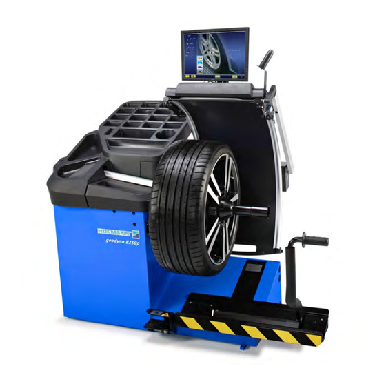
- Page 1 8200 geodyna 8250 Betriebsanleitung Radauswuchtmaschine Operator’s Manual Wheel balancer Manuel Opérateur Équilibreuse Roues...
- Page 2 FAMILY NAME MODELS DESCRIPTION of the MACHINE Power Clamp system. geodyna 8200 8200-2 p Power Clamp system. geodyna 8200 8200-2 p Power Clamp system / Lifting system. geodyna 8250 8250-2 p Power Clamp system / Lifting system. geodyna 8250 8250-2 p...
- Page 3 - NOTES REGARDING DOCUMENTATION - ITA NOTE SULLA DOCUMENTAZIONE - ANMERKUNGEN ZUR DOKUMENTATION - ESP NOTAS SOBRE LA DOCUMENTACIÓN - NOTES SUR LA DOCUMENTATION - POR NOTAS SOBRE A DOCUMENTAÇÃO - ПРИМЕЧАНИЯ ПО ДОКУМЕНТАЦИИ Product aid publication: Pubblicazione di supporto al prodotto: WHEEL BALANCER EQUILIBRATRICE Zum Produkt gehörendes Dokument:...
- Page 4 WARRANTY TERMS AND LIMITATIONS OF UPDATES REPORT LIABILITIES While the authors have taken care in the preparation Release A -____________________-May 2017 of this manual, nothing contained herein: modifies or alters in any way the standard terms “-2” version PCN:17G0092 and conditions of the purchase, lease or rental agreement under the terms the equipment to Release B -__________________-August 2017 which this manual relates was acquired...
- Page 5 LIMITES D’APPLICATION DE LA GARANTIE ET GEWÄHRLEISTUNGS- UND LIMITATIONS DE LA GARANTIE HAFTUNGSAUSSCHLUSS Bien que les auteurs aient accordé la plus grande Die Informationen in dieser Bedienungsanleitung attention à la rédaction du présent manuel, aucun wurden gewissenhaft und sorgfältig zusammengestellt. élément figurant dans ce dernier : D e r I n h a l t o d e r Te i l e d e s I n h a l t s d i e s e r ne modifie les conditions et les termes standards...
- Page 6 Safety Safety Important safety precautions relevant to the unit are described in the Safety Booklet, refer to Figure 1 – 1. The safety precautions should be fully understood and observed by every operator. We suggest you store a copy of the Safety Booklet near the unit, within easy reach of the operator.
- Page 7 Sécurité Sicherheit Sécurité Sicherheit Les mesures de sécurité importantes relatives à l’unité Wichtige Sicherheitsmaßnahmen für dieses Gerät sind im sont décrites dans le Livret de Sécurité, voir Figure 1-1. Sicherheitshandbuch beschrieben; siehe Abbildung 1-1. Les consignes de sécurité doivent être totalement Die Sicherheitsmaßnahmen müssen von allen Bedienern comprises et observées par chaque opérateur.
- Page 8 Specifications 2.0 Specifications geodyna 8200 geodyna 8250 Wheel Balancers specs Car, light truck, moto Vehicles supported < 200 rpm Measuring speed 1 g (0.035 oz) Balancing accuracy 0.7° Angular resolution 40 mm (1.57 inch) Diameter of shaft 225 mm Length of shaft...
-
Page 9: Spécifications
Specifications Spezifikationen Spécifications 2.0 Spezifikationen Rad-Auswuchtmaschinen Daten Données Equilibreuses Véhicules compatibles Unterstützte Fahrzeuge Vitesse de mesure Messgeschwindigkeit Précision d'équilibrage Auswuchtgenauigkeit Résolution angulaire Winkelauflösung Diamètre arbre Durchmesser der Welle Longueur arbre Länge der Welle Offset bride équilibreuse Versatz Felgenhorn Auswuchtmaschine Temps d'équilibrage - Rotation de contrôle (Roue 195/65R15) Start/Stopp Auswuchtzeit - Kontrolle Drehung (Rad 195/65R15) Marche/Arrêt temps d'équilibrage - Données (Roue 195/65R15) Start/Stopp Auswuchtzeit - Daten (Wheel 195/65R15) - Page 10 Introduction 3.0 Introduction This wheel balancer combines advanced, high- performance technology, robustness and reliability with very simple, user-friendly operation. The low rotation speed of the wheel ensures that this balancer is very safe. The colour monitor shows the data set, operating modes, values measured, symbols and operator help information.
- Page 11 Introduction Einführung 3.0 Einführung 3.0 Introduction Dieses Auswuchtgerät verbindet hochmoderne Cette équilibreuse vous offre une technologie avancée Hochleistungstechnik, Robustheit und Zuverlässigkeit de haute performance, solidité et fiabilité et son mit einfachem, benutzerfreundlichem Betrieb. opération est très simple et conviviale. Durch die niedrige Rotationsgeschwindigkeit des Rades La faible vitesse de rotation de la roue assure que ist das Auswuchtgerät extrem sicher in der Benutzung.
-
Page 12: Accessories
Accessories Accessories Refer to Figure 3-1. The standard accessories are: Power Clamp Nut EAM0086G86A Plastic Sleeve EAC0058D69A Universal drum cushion EAC0058D15A Universal drum EAC0058D07A Spacer ring EAC0058D08A Large cone EAM0005D25A Medium cone EAM0005D24A Small cone EAM0005D23A Calibration weight EAM0005D40A Weight pliers 8-04250A Gauge EAA0247G21A... -
Page 13: Accessoires
Accessoires Zubehör Accessoires Zubehör Se reporter à la Figure 3-1. Siehe Abbildung 3-1. Les accessoires standard sont : Das folgende Standardzubehör steht zur Verfügung: Embout de blocage Power Clamp Power Clamp Spannmutter EAM0086G86A EAM0086G86A Manchon en plastique Druckmuffe aus Kunststoff EAC0058D69A EAC0058D69A Joint protection de la coupelle... - Page 14 Layout 4.0 Layout Refer to Figure 4-1. Functional description of the unit: 1. Touch screen Refer to Chapter 4.1. 2. Wheel guard 3 External Detector - Sonar Refer to Chapter 4.8. 4. Stub shaft 5. Gauge arm Refer to Chapter 4.7. 6.
-
Page 15: Affichage
Disposition Layout Disposition 4.0 Layout Se reporter à la Figure 4-1. Siehe Abbildung 4-1. Description fonctionnelle de la machine : Funktionsbeschreibung des Geräts: 1. Affichage 1. Berührungseingabe Bildschirm Se reporter au Chapitre 4.1. Siehe Kapitel 4.1. 2. Carter de roue 2. - Page 16 Layout The screen Fig. 4-3 Screen with display fields. Display field. Information field. Commands field. The screen reads out inputs, helpful information, all measured data and possible error codes. Description of displayed fields Each field of the screen has a specific function. Display field Rim dimensions (editable).
- Page 17 Disposition Layout Écran 4.1 Bildschirm Fig. 4-3 Écran avec zones d’affichage. Bildschirm mit Anzeigezonen. Abb. 4-3 Zone d’affichage. Anzeigefeld Informationsfeld Zone d’information. Steuerungsfeld Zone Commandes. Sur l’écran sont affichés les paramètres, les textes Auf dem Bildschirm werden die jeweiligen Eingabedaten, d’aide, toutes les valeurs mesurées et les messages bedienerunterstützende Informationen, alle ermittelten d’erreur.
- Page 18 Layout 4.1.1 Fundamental Commands Figure 4-4 Keypad 1 Type of basic key (this type of key is always located in the Commands Field). 2 HOME key 3 ESC key 4 HELP key 5 START key 6 STOP key 7 CONFIRMATION key 8 RETURN key Description of keys 1 Keys (example)
-
Page 19: Commandes De Base
Disposition Layout 4.1.1 Grundbefehle 4.1.1 Commandes de base Figure 4-4 Clavier Abbildung 4-4 Tastatur 1 Art von Haupttaste (diese Art von Taste ist immer im 1 Type de touche fondamentale (ce type de touche Feld der Befehle vorgesehen) se trouve toujours dans le Champ Commandes). 2 Touche HOME 2 HOME-Taste 3 ESC-Taste... - Page 20 Layout 4.1.2 Screen pages & Commands The Display field shows the main Operating Screen Pages. Each Screen Page contains basic commands, located at the bottom in the Commands Field. Further com- mands may be positioned in other parts of the screen, with specific Screen Pages and operating phases.
- Page 21 Disposition Layout 4.1.2 Pages-écran & Commandes 4.1.2 Die Display-Seiten / Menü La zone Affichage donne accès aux principales pages- Im Anzeigefeld sind die wichtigsten Betriebsseiten écran opérationnelles : dargestellt: Chaque page contient des commandes de base, si- Auf jeder Bildschirmseite sind die fundamentalen tuées en bas dans le Champ Commandes.
- Page 22 Layout Fig. 4-6 RIM DATA ENTRY Rim data entry Screen. Open using the Manual Data Entry key (3, Fig. 4-5). Specific commands: 1 - HELP key - Selects HELP texts. 2 - HOME key - Returns you to the starting page (INTRO SCREEN).
- Page 23 Disposition Layout Fig. 4-6 RIM DATA ENTRY Abb. 4-6 RIM DATA ENTRY Page-écran de saisie des données de la roue. Der Seite zur Eingabe der Daten. Pour accéder à la page, presser la touche Manual Sie wird über die Taste Manual Data Entry aufgerufen Data Entry (3, Fig.
- Page 24 Layout Fig. 4-7 BALANCING Balancing Screen. Open with the BALANCING key (5, Fig. 4-5). Commands: 1 - HELP key - For selecting HELP texts. 2 - HOME key - Returns you to the starting page (INTRO SCREEN). 3 - START key - Starts the measuring run. 4 - ESC key - To exit the option being executed or displayed.
- Page 25 Disposition Layout Fig. 4-7 BALANCING Abb. 4-7 BALANCING Page-écran Équilibrage. Bildschirm Auswuchten. Pour accéder à la page, presser la touche BALANCING Der Zugriff erfolgt über die Taste BALANCING (5, (5, Fig. 4-5). Abb. 4-5). Commandes : Die Befehle sind: 1 - Touche HELP - Sélection de textes d’AIDE. 1 –...
- Page 26 Layout Fig. 4-8 SETTINGS Settings Screen. Open with the SETTINGS key (7, Fig. 4-5). Commands: 1 - HELP key - For selecting HELP texts. 2 - HOME key - Returns you to the starting page (INTRO SCREEN). 3 - USER CAL key - Starts the USER CALIBRATION ...
- Page 27 Disposition Layout Fig. 4-8 Abb. 4-8 SETTINGS SETTINGS Page-écran Paramètres. Einstellungen Bildschirm. Der Zugriff erfolgt über die Taste SETTINGS (7, Abb. Pour accéder à la page, presser la touche SETTINGS (7, Fig. 4-5). 4-5). Commandes : Die Befehle sind: 1 - Touche HELP - Sélection de textes d’AIDE. 1 –...
- Page 28 Layout Fig. 4-10 OPTIMISATION/MINIMISATION Optimisation / Minimisation Screen. Open with the OPT/MIN key (6, Fig. 4-7) when on the Screen after a measuring run. Commands available during the entire cycle: 1 - HELP key - Selects HELP texts relating to the current function.
- Page 29 Disposition Layout Fig. 4-10 OPTIMISATION/MINIMISATION Abb. 4-10 L A U F R U H E N O P T I M I E R U N G / GEWICHTEMINIMIERUNG Page Optimisation de stabilité de marche/ Minimisation des masses.. B i l d s c h i r m L a u f r u h e n o p t i m i e r u n g / On accède à...
- Page 30 Layout 4.1.3 Settings After switching on the unit, a default weight mode is shown. If the unit then shows another weight mode, 5.5.3. The unit of measurement indicated at power up is inches, but the setting selected before switching off for grams / ounces remains.
-
Page 31: Commutation Unités Dimensionnelles
Disposition Layout 4.1.3 Réglages 4.1.3 Einstellungen Après l’allumage de l’unité un type de roue est affiché Nach dem Einschalten des Geräts wird ein par défaut. Si l’unité montre ensuite un type de roue standardmäßiger Gewichtsmodus angezeigt. Sehen différent, 5.5.3. - Page 32 Layout Pictographs and symbols Piktogramme • Pictographs • Pictogrammes Pictographs are viewed on the screen in all fields: in Information, Menu and Display fields. P1 Wheel type 1 - standard wheel - nominal size in inches or millimetres. P2 Wheel type 2 - motorcycle wheel P3 Alu 0 - normal - Standard weight positioning P4 Alu 1, Alu 1P P5 Alu 2, Alu 2P...
-
Page 33: Symboles - Pictogrammes
Disposition Layout Symbolbilder - Piktogramme Symboles - Pictogrammes Sur l’écran, des pictogrammes sont affichés dans toutes Auf dem Bildschirm werden Piktogramme in allen les zones d’affichage : dans les zones d’information, Anzeigezonen dargestellt: In Informationsfeldern, les zones de menu et dans la zone d’affichage. Menüfeldern und im Anzeigefeld. - Page 34 Layout Piktogramme • Pictographs • Pictogrammes Symbols relating to OPTIMISATION / MINIMISATION operations P15 Start the measuring run. P16 Apply the Calibration weight. P17 Make a mark on left tyre side. P18 Make a mark on right tyre side. P19 Fit tyre on rim and inflate to the specified inflation pressure.
- Page 35 Disposition Layout Piktogramme zur Darstellung der Vorgänge Symboles utilisés pour les opérations d’OPTIMISATION/MINIMISATION OPTIMIERUNG / MINIMIERUNG P15 Le démarrage du lancement roue est demandé P15 Der Messlauf muss gestartet werden. P16 L’application de la masse-étalon est demandée P16 Das Justiergewicht muss angebracht werden. P17 Placer repère à...
-
Page 36: Help Information
Layout Help information Help information explains the current action and, in the case of an error code, provides hints for remedy. 4-12 Display help information Press the HELP key (Fig. 4-12). The first screen with help information appears, e. g. to the screen WHEEL DATA ENTRY (Fig. -
Page 37: Guide De Dépannage
Disposition Layout Textes d’aide Hilfetexte Les textes d’aide expliquent l’opération en cours et HIlfetexte erläutern den aktuellen Handlungsschritt und donnent des consignes en cas de messages d’erreur geben bei Fehlermeldungen Hinweise zur Bearbeitung. pour pouvoir trouver un remède. Hilfetext aufrufen ... - Page 38 Layout The screen relating to the fault appears, showing initial or basic information (Fig. 4-18). Press the stop key (Fig. 4-19). The second screen relating to the fault appears, showing more detailed and second level information (Fig. 4-20). Press the stop key (Fig. 4-19) to quit the HELP page. 4-18 4-19 Electromechanical stop...
-
Page 39: Arrêt Électromécanique
Disposition Layout Die Bildschirmseite, die sich auf den gemeldeten Fehler La page relative à l'erreur signalée apparaît en fournissant une information initiale ou de premier bezieht, wird angezeigt. Sie gibt eine anfängliche Information oder eine Information ersten Niveaus über niveau à propos de l'anomalie (Fig. 4-18). die Störung (Abb. - Page 40 Layout Stop brake Figure 4-22 Pedal of wheel stop brake Activate the pedal to brake the wheel holder chuck and make fixing nut clamping or unclamping easier. The wheel is also retained in the correct position to allow for an easier weight application. Warning: This stop brake is designed only to facilitate orientation of the wheel and must not be used for...
-
Page 41: Blocage De L'arbre Principal
Disposition Layout Blocage de l’arbre principal Feststellbremse Figure 4-22 Pédale de blocage Bild 4-22 Pedal der Feststellbremse L’arbre principal est bloqué quand la pédale est Bei getretenem Pedal wird die Hauptwelle festgestellt. actionnée. Cela permet de serrer ou de desserrer Hierdurch wird das Anziehen bzw. - Page 42 Layout Measuring Gauge Figure 4-23 Measuring Gauge to measure distance and diameter Gauge, it can be extracted and extended upwards Stick-on weight holder jaw to measure the application position and to fix the compensation weight Stick-on weight fitted Gauge head to identify rim dimension on a variety of rim profiles.
-
Page 43: Détecteur À Ultrasons
Disposition Layout Piges de mesure Messarm Figure 4-23 Pige de mesure pour écart et diamètre Abbildung 4-23 Messarm für Abstand und Durchmesser de la jante Pige de mesure télescopique et pivotable vers Messarm, ausziehbar und nach oben schwenkbar le haut Gewichtepratze zum Fixieren des Klebegewichts für das Antasten der späteren Anbringposition Porte-masse pour tenir la masse autocollante... - Page 44 Operation 5.0 Operation Power up Be sure to be familiar with: - possible dangers, ( 1.0) - the unit ( 4.0). Please read through the operation manual and follow the instructions, especially when operating the wheel balancer for the first time. ...
-
Page 45: Utilisation
Utilisation Betrieb 5.0 Utilisation 5.0 Betrieb Allumage Start Veuillez-vous familiariser avec : Machen Sie sich mit Folgendem vertraut: - les dangers possibles, ( 1.0) - möglichen Gefahren, ( 1.0) - la machine ( 4.0). - der Einheit ( 4.0). -
Page 46: Status At Switching On
Operation 5.1.2 Status at switching on The electronic unit is factory-adjusted to the following operating modes, available after switch on: – AUTOMATIC Operating Mode – Wheel type 1 (car wheel with nominal dimensions in inches, width 6.5” and diameter 15.0”). –... -
Page 47: État À La Mise En Circuit
Utilisation Betrieb 5.1.2 État à la mise en circuit 5.1.2 Einschaltzustand L’unité électronique est programmée par le fabricant Die Elektronik ist werksseitig so programmiert, de façon que les modes de fonctionnement suivants dass nach dem Einschalten sofort ’die folgenden soient, disponibles juste après le démarrage : Funktionsweisen gegeben sind: –... -
Page 48: Clamping/Unclamping The Wheel
Operation Clamping/unclamping the wheel The electronics is so programmed that after turning on the machine, the clamping jaws remain in their current position and any movement must be activated intentionally by activating the pedal. 5.2.1 Clamping the wheel Note: Before clamping the wheel make sure the contact surfaces on wheel adaptor and rim are free from dirt and grease. -
Page 49: Serrage / Desserrage De Roue
Utilisation Betrieb Serrage / desserrage de roue Rad aufspannen/abspannen La commande électrique est conçue telle qu’après Die elektrische Steuerung ist so ausgelegt, dass nach la mise en circuit de l’interrupteur secteur les mors dem Einschalten des Netzschalters die Spannklauen de serrage restent dans leur position instantanée et in der momentanen Stellung verbleiben und eine que tout changement doit être effectué... - Page 50 Operation (if present): 5.2.2.1 Using the Automatic Lifter Fig. 5-8b The lifter ascends automatically as soon as the operator operates the pedal for wheel removal. After removing the clamping tool from the shaft. – Support the wheel, then move the platform out of the shaft area, towards the right.
-
Page 51: Utilisation De L'élévateur Automatique (Si Présent)
Utilisation Betrieb 5.2.2.1 Utilisation de l’élévateur automatique 5.2.2.1 Einsatz des automatischen Hebers (si présent) : (wenn vorhanden): Fig. 5-8b Abb. 5-8b L’élévateur monte automatiquement dès que Der Heber hebt sich automatisch sobald der l’opérateur actionne la pédale pour retirer la Bediener das Pedal bedient, um das Rad zu roue. - Page 52 Operation Adapters for wheels without centre bore In order to work on rims without centre bore or to be fixed with the bores of stud-bolts or for example motorcycle wheels, the MZV-p device can be replaced with the clamping tool SCA, or with the ”Motorbike base Flange”...
-
Page 53: Replacement Du Moyen De Serrage Pour Roues Sans Trou Central
Utilisation Betrieb Replacement du moyen de Adapter für Felgen ohne serrage pour roues sans trou central Mittenloch Pour le centrage et le serrage des jantes sans trou Sollen auf der Maschine Felgen ohne Mittenloch central ou des roues de moto sur une équilibreuse ü... - Page 54 Operation Mounting the Power Clamp device No wheel should be mounted on the machine. Warning: When the Power Clamp device must be refitted on the machine, set the operating mode C22 to “disabled”; Releasing the power clamping device is disabled. Refer to Fig.
- Page 55 Utilisation Betrieb Montage du moyen de serrage Power Clamp Montage der Spannvorrichtung Power Clamp Il n’y a pas de roue sur la machine. Es befindet sich kein Rad auf der Maschine. Mise en garde : Warnhinweis: Si la machine est à nouveau modifiée pour le moyen Wenn die Maschine wieder auf die Spannvorrichtung de serrage Power Clamp, remettre le mode C22 à...
- Page 56 Operation 5 . 4 W e i g h t a p p l i c a t i o n a n d Measurement methods 5.4.1 Weight application positions Normal Standard positioning of weights, spring weights on the rim edges (steel). Symmetrical application of stick-on weights Alu 1 on rim shoulders (aluminium).
-
Page 57: Modes D'application Des Masses Et Relevé Des Mesures
Utilisation Betrieb 5.4 Applikationsformen der Gewichte 5.4 Modes d’application des masses et relevé des mesures und Erfassung der Maße 5.4.1 Applikationspositionen für Gewichte 5.4.1 Positions d’application des masses Normal Normale Anordnung der Gewichte, Gewichte Normal Positionnement normal des masses, masses mit Federn an den Felgenrändern (Stahl). - Page 58 Operation 5 . 5 D a t a r e q u i r e d f o r w e i g h t application Normal Offset Distance (machine rim) Rim nominal diameter Rim nominal width Offset Distance (machine rim) Alu 1 Rim nominal diameter Rim nominal width...
-
Page 59: Données Nécessaires Pour L'application Des Masses
Utilisation Betrieb 5.5 Für die Anbringung der Gewichte 5.5 Données nécessaires pour l’application des masses erforderliche Daten Normal Abstand Offset (Maschine Felge) Normal Distance Offset (machine jante) Nominaler Felgendurchmesser Diamètre nominal de la jante Nominale Felgenbreite Largeur nominale de la jante Abstand Offset (Maschine Felge) Distance Offset (machine jante) Alu 1... - Page 60 Operation 5.6 Data detection mode 5.6.1 Selections by the User For adequate rounded results and for a correct application of thresholds, select, before the measuring run: the operating mode (Fig. 5-15a). The Type of Vehicle before the measuring run. (Fig. 4-6) 5.6.2 Selecting the Type of Vehicle...
-
Page 61: Mode De Saisie Des Données
Utilisation Betrieb 5.6 Mode de saisie des données 5.6 Betriebsart „Datenerfassung“ 5.6.1 Vom Benutzer getroffene Wahlen 5.6.1 Sélections par l’utilisateur Pour des arrondissements adéquats des résultats Für angemessene Abrundungen der Ergebnisse und et pour une application correcte des seuils, il est eine korrekte Verwendung der Schwellenwerte muss nécessaire de sélectionner avant le lancement de vor dem Messlauf Folgendes gewählt werden:... - Page 62 Operation W h e e l m e a s u r i n g r u n (AUTOMATIC) Note: Starting from the completely lifted position, lower the wheel guard, at medium speed without stops or jerks even to the side. Warnings: You must be very careful when lowering the guard, as the machine simultaneously detects the diameter,...
-
Page 63: Le Cas Échéant, La Largeur Pourra Être Saisie
Utilisation Betrieb Messlauf (AUTOMATISCH) L a n c e r l a r o u e ( M o d e AUTOMATIQUE) Hinweis: Den Radschutz ausgehend von der vollkommen gehobenen Position der Remarque : Abaisser la protection roue en partant Abdeckung bei geringer Geschwindigkeit de la position de carter complètement soulevé, u n d r e g u l ä... -
Page 64: Advanced Spoke Detection
Operation 5.7.1 Advanced Spoke Detection This mode, to be enabled in case of need and only in “BALANCING” ( 5.9) and “BALANCE WITH RUN OUT” modes ( 5.8), allows exact identification of rim spokes position and size. It allows a more precise placement of weights behind the spokes. -
Page 65: Identification Avancée Rayons
Utilisation Betrieb 5.7.1 Identification avancée rayons 5.7.1 E r w e i t e r t e F e l g e n - / Speichenerkennung Ce mode, à activer si besoin est, exclusivement en Dieser Modus kann bei Bedarf ausschließlich ... - Page 66 Operation AUTOMATIC Mode “BALANCE WITH RUN OUT” The following instructions describe the specific functions of the balancer in the “BALANCE WITH RUN OUT” mode. Icon shown in (Fig. 5-15) identifies active “BALANCE WITH RUN OUT” mode. The unit runs in automatic 5-15 mode.
- Page 67 Utilisation Betrieb M o d e A U T O M A T I Q U E A U T O M A T I S C H E « BALANCE WITH RUN OUT » BETRIEBSART „AUSWUCHTUNG MIT RUN OUT” Les instructions suivantes décrivent les fonctionnalités spécifiques de l’équilibreuse dans le mode In den folgenden Anleitungen werden die spezifischen...
- Page 68 Operation As soon as run-out is measured, screen shows key (1, Fig. 5-19); press it to open the charts referred to the just-performed run-out reading. Instance when run-out is “below range”: (Fig. 5-20) all values are green and the screen shows “OK”. Instance when run-out is “out of range”: (Fig.
- Page 69 Utilisation Betrieb Lorsque le contrôle de l’excentration aura été effectué, Nach erfolgter Seiten- und Höhenschlagmessung la page-écran avec le bouton (1, Fig. 5-19) s’affiche, en (Runout) wird die Bildschirmseite über die Taste (1, y appuyant dessus on accède aux graphiques relatifs Abb.
-
Page 70: Print Report
Operation 5.8.1 Print Report After enabling the printing function of the screen page in the settings page, the print key is available (1). By pressing key (1) all the three available options will be shown: 2 - Single report prints 3 - Multiple report prints 4 - Current screen prints 5-98... -
Page 71: Impression Du Rapport
Utilisation Betrieb 5.8.1 Impression du Rapport 5.8.1 Bericht drucken Une fois la fonction d'impression de la page-écran Wenn die Druckfunktion der Bildschirmseite auf der des réglages habilitée, la touche d'impression est Seit der Einstellungen aktiviert ist, ist die Drucktaste disponible (1). (1) verfügbar. - Page 72 Operation 5.8.2 Geometric Matching Open the Matching procedure by pressing key 1 (Fig. 5-101). The Geometric Matching screen will open (Fig. 5-101). 5.8.2.1 Geometric Matching At the end of the wheel measuring run the balancer may prompt carrying out a geometric matching (icon at the top left of the screen), whose diagnosis can provide a substantial improvement to the wheel performance.
-
Page 73: Centrage Géométrique
Utilisation Betrieb 5.8.2 Centrage géométrique 5.8.2 Geometrisches Matching Il est possible d’accéder à la procédure de Centrage Das Verfahren des Matching ist zugänglich über die avec la touche 1 (Fig. 5-101). Taste 1 (Abb. 5-101). La page-écran du Centrage géométrique apparaît Es erscheint die Bildschirmseite geometrisches (Fig. -
Page 74: Automatic Mode
Operation AUTOMATIC Mode “BALANCING” The following instructions describe the specific functions of the wheel balancer in AUTOMATIC mode, “BALANCING”. Icon shown in (Fig. 5-23) indicates the “BALANCE” 5-23 mode is active. The unit operates in Automatic Mode. When the “BALANCING” mode is set via setup panel, the machine performs the automatic wheel data reading procedure and the user does not have to perform any setting before the measuring run (except... - Page 75 Utilisation Betrieb Mode AUTOMATIQUE AUTOMATISCHE Betriebsart « ÉQUILIBRAGE » AUSWUCHTUNG” Les instructions suivantes décrivent les fonctionnalités Die folgenden Anleitungen beschrieben die spezifischen spécifiques de l’équilibreuse dans le mode Funktionen der Auswuchtungsanlage währen der AUTOMATIQUE, « ÉQUILIBRAGE ». AUTOMATISCHEN Betriebsart „AUSWUCHTUNG”. L’icône de la (Fig.
- Page 76 Operation 5.9.1 Rim Data Freeze The “Rim Data Freeze” function allows you to save the data detected on a first rim, of a group of identical wheels (usually four) to be balanced. This function enhances machine performance since it reduces the data acquisition time for the subsequent identical wheels after the first.
-
Page 77: Bloquer Les Données De La Roue
Utilisation Betrieb 5.9.1 Bloquer les données de la roue 5.9.1 Sperre der Raddaten Cette fonctionnalité, dénommée « Rim Data Freeze », Mit dieser Funktion, die entsprechend mit „Rim Data permet de mémoriser les données mesurées sur une Freeze” bezeichnet wird, ist es möglich, die Daten, die première jante pour un groupe de roues identiques an der ersten Felge einer Reihe an auszuwuchtenden (généralement quatre) à... - Page 78 Operation The Rim data freeze condition set is also identified by the icon shown on the right of the monitor, with the following meaning: (Fig. 5-36) a) Yellow hatching for external and internal detectors, indicating that the Wheel Data Freeze function is not activated.
- Page 79 Utilisation Betrieb La condition paramétrée de bloc données roue « Rim Der eingestellte Zustand „Rim data freeze“ wird data freeze » est signalée aussi par une icône sur auch anhand des Symbols angezeigt, das rechts am l’écran à droite, à interpréter comme suit : Bildschirm dargestellt ist und folgende Bedeutung hat: (Fig.
- Page 80 Operation 5.10 SPOKES OFF AUTOMATIC Mode “BALANCE NO SPOKES” The Spokes Off Automatic Mode has the same features as the Automatic function already described ( 5.9), except that it excludes automatic rim spoke detection. When it is established that no information about spokes is needed, in-depth spoke detection by the laser can be switched off.
- Page 81 Utilisation Betrieb 5.10 M o d e A U T O M A T I Q U E 5.10 AUTOMATISCHE Betriebsart RAYONS EXCLUS « ÉQUILIBRAGE SPEICHEN AUSGESCHLOSSEN SANS RAYONS » „AUSWUCHTUNG OHNE SPEICHEN“ Le mode Automatique Rayons exclus a les mêmes D i e a u t o m a t i s c h e B e t r i e b s a r t „...
- Page 82 Operation 5.11 Wheel measuring run (in Manual) This function is retrieved with the key (1, Fig. 5-41) available in the main Menu. – Check the wheel is clamped correctly ( 5.2). – Select the Type of Vehicle ( 5.6.2).
-
Page 83: Si Plusieurs Roues Du Même Type (Dimensions Nominales De Jante Identiques) Sont Équilibrées
Utilisation Betrieb 5.11 M e s s l a u f ( i n m a n u e l l e r 5.11 L a n c e m e n t d e r o u e ( e n Betriebsart) Manuel) Diese Funktion kann über die Taste (1, Abb. - Page 84 Operation 5.11.2 MANUAL Mode with gauge arm. The gauge arm is used to enter the distance between the machine and the rim, as well as the nominal rim diameter. Note: Wheel width must be entered manually. • Make sure that the gauge arm (1) is in its home position.
- Page 85 Utilisation Betrieb 5.11.2 Mode MANUEL avec identification 5. 11 .2 M ANUE LLE Bet ri ebsar t m it du bras. Abtastarm. Le bras est utilisé pour introduire l'écart entre la Der Abtastarm wird verwendet, um den Abstand machine et la jante et le diamètre nominal de la jante. u n d D u r c h m e s s e r z w i s c h e n M a s c h i n e u n d Nenndurchmesser der Felge eingeben zu können.
-
Page 86: Easy Alu Function
Operation “MANUAL MODE” 5.12 Easy Alu function The Easy Alu function automatically recognises the Alu required by the operator and the rim dimension parameters, once the gauge has been positioned on the rim. The machine presents only the possible Alu modes (Fig. - Page 87 Utilisation “MANUAL MODE” Betrieb “MANUAL MODE” 5.12 Die Funktion „Easy Alu“ 5.12 Fonction Easy Alu La fonction Easy Alu consiste à reconnaître Das Easy Alu-System hat die Funktion, den automatiquement l’Alu voulu par l’opérateur et les vom Anwender gewünschten Alu-Modus und die dimensions de la jante, suite au positionnement du Abmessungsparameter der Felge automatisch zu palpeur sur la jante.
- Page 88 Operation “MANUAL MODE” Suggestion Even if it is available, we suggest you do not select the ALU mode manually for normal balancing procedures. Changing the ALU in fact, if carried out before or after a run, cancels the use of the Real Data obtained with the Easy Alu procedure.
- Page 89 Utilisation “MANUAL MODE” Betrieb “MANUAL MODE” Conseil Empfehlung Bien que disponible, la sélection manuelle d’un mode Die manuelle Wahl eines ALU-Modus ist für das Alu n’est pas conseillé pour les opérations d’équilibrage normale Auswuchtverfahren nicht empfehlenswert, habituelles. Le changement d’Alu, en effet, exécuté auch wenn die Möglichkeit dafür besteht.
- Page 90 Operation “PROFILING” 5.13 Selections by the User Manual Mode with available data entry The Type of Vehicle must always be set and it must be done before extracting the arm to read the rim positions. 5.13.1 Distance manual entry X = Distance between cabinet edge and rim A = Value X (as measured) less 5 mm (= Value to be entered).
- Page 91 Utilisation “PROFILING” Betrieb “PROFILING” 5.13 Sélections de la part de 5.13 Benutzerauswahl „Manuelle l'utilisateur du mode manuel Betriebsart“ mit Eingabe der avec introduction des données verfügbaren Daten disponibles Die Einstellung des Fahrzeug-Typs ist immer erforderlich und muss vor dem Herausziehen des Il est toujours nécessaire de sélectionner le type de Abtastarms für die Messung der Positionen auf der véhicule.
- Page 92 Operation “MANUAL MODE” Wheel Profiles function 5.14 To balance more than one wheel of the same type and with the same nominal dimensions, simply set the data for the first wheel only. The data set remain until other new data are set or the machine is switched off. Note: This function in used in manual mode only.
-
Page 93: Fonction Profils De Roue
Utilisation “MANUAL MODE” Betrieb “MANUAL MODE” Fonction Profils de roue Funktion „Radprofile“ 5.14 5.14 Si plusieurs roues du même type et de valeurs Werden mehrere Räder des gleichen Radtyps und nominales identiques sont équilibrées, les dimensions mit gleichen Nennmaßen ausgewuchtet, müssen die de la roue ne doivent être entrées que pour la première Radmaße nur für das erste Rad eingegeben werden. - Page 94 Operation “MANUAL MODE” 5.14.1 Saving a Wheel Profile Up to 9 wheel profiles can be saved. Clamp the wheel you wish to save the profile of. Set and acquire all the wheel data, including the number of spokes if an Alu P is required. 5-48 In the RIM DATA ENTRY screen press the “SPECIAL”...
-
Page 95: Mémorisation D'un Profil De Roue
Utilisation “MANUAL MODE” Betrieb “MANUAL MODE” 5.14.1 Speicherung der Radprofile 5.14.1 Mémorisation d’un profil de roue Il est possible de mémoriser un maximum de 9 profils Es können bis zu 9 Radprofile gespeichert werden. de roue. Das Rad aufspannen, dessen Profil Sie speichern Mettre en place la roue dont on souhaite mémoriser möchten. -
Page 96: Weight Application
Operation 5.15 Weight application The following weight types and application methods are available: Clip-on weights. Always apply by hand (Figure 5-23). Stick-on weights. After wheel run, look at the rotation indicators for the left plane of the wheel (1, Fig. 4-13): •... -
Page 97: Pose Des Masses
Utilisation Betrieb 5.15 Anbringen der Gewichte 5.15 Pose des masses Es stehen die folgenden Arten von Gewichten und Les types de masses et méthodes de pose suivantes Anbringungsmethoden zur Verfügung: sont disponibles: Klemmgewichte. Masses agrafées. Diese werden immer von Hand angebracht Poser toujours manuellement (Figure 5-23). - Page 98 Operation 5.15.3 Alu 2P and Alu 3P weight application modes: 5.15.3.1 Using the Laser Pointer With the Laser Pointer mode active in Alu 2P and Alu 3P modes, the correction planes for stick-on weights are accurately indicated by the laser pointer directly on the rim (Fig.
-
Page 99: Modes De Pose Des Masses Alu 2P Et Alu 3P
Utilisation Betrieb 5.15.3 Anbringungsformen der Gewichte 5.15.3 Modes de pose des masses Alu 2P Alu 2P und Alu 3P: et Alu 3P : 5.15.3.1 Utiliser le Laser Pointer 5.15.3.1 Anwendung des Laserzeigers Avec le mode Laser Pointer actif, dans les modes Alu Bei aktiver Laserpointer-Funktion werden die Ausgleichsebenen für die Klebegewichte in den 2P et Alu 3P, les plans de correction pour les masses... - Page 100 Operation 5.15.3.2 Using the gauge arm Note: Using the gauge arm is an alternative option to using the laser pointer for weight application. Warning: For top weight application with arm tip, Laser Pointer will have to be disabled. Refer to (Figure 5-28). The gauge arm must be used to apply the stick-on weights.
-
Page 101: Application Avec Bras Palpeur
Utilisation Betrieb 5.15.3.2 Application avec bras palpeur 5.15.3.2 Anbringen mit Messarm Remarque : L'utilisation du bras palpeur reste une Hinweis: Die Verwendung des Abtastarms bleibt option alternative à l'application de la masse avec eine Alternative zur Gewichtanbringung mittels le Laser Pointer. Laserpointer. -
Page 102: Behind-The-Spokes Placement
Operation 5.15.4 Behind–the–spokes placement - SWM (Split Weight Mode) The behind-the-spokes placement mode (SWM) allows to split balance weights that, according to the machine, would have to be fitted in a visible position that probably the customer would not like. With the SWM Mode instead, two weights, equivalent to the first one, are placed behind the closest spokes (see example, Figure 5-57). -
Page 103: Positionnement Des Masses Derrière Les Rayons - Swm (Split Weight Mode)
Utilisation Betrieb 5.15.4 Positionnement des masses 5.15.4 Hinterspeichenplatzierung der Gewichte - SWM (Split Weight Mode) derrière les rayons - SWM (Split Weight Mode) D a s A u s w u c h t p r o g r a m m f ü... - Page 104 Operation Note: We suggest you keep the wheel in position with the brake pedal until the selection has been made. Use key (17,Fig. 5-60) to select the Item Hidden Weight behind spokes. The function is now selected and on the right of the 5-60 screen two balancing indicators are shown instead of one (Fig.
- Page 105 Utilisation Betrieb Hinweis: Wir empfehlen, das Rad mithilfe des Remarque : Il est conseillé de bloquer la roue Bremspedals in der Position zu halten, bis en position avec le frein de blocage die Wahl beendet ist. jusqu’à la fin de la sélection. ...
- Page 106 Operation 5.15.4.2 Hidden Weights placement Application of stick-on weights on the left side of the rim channel Clean the fitting position before attaching the stick- on weights. Fit the stick-on weight on the left side of the rim channel (Figure 5-63).
-
Page 107: Fixation D'une Masse Cachée
Utilisation Betrieb 5.15.4.2 A n b r i n g e n d e r v e r s t e c k t e n 5.15.4.2 Fixation d’une masse cachée Klebegewichte Placer la masse autocollante sur le côté Anbringen des Klebegewichts auf der linken gauche du disque de jante Seite der Felgenschüssel ... -
Page 108: Results Recalculation
Operation 5.16 Check run It is good practice to perform a check run after applying the weights. • Start the run. Having finished the check run, if the wheel is balanced correctly, both the numerical indicators should indicate 0 and an OK should be displayed (Fig. 5-56). Warning If both unbalance value indicators show 0, but there is no OK reading, dynamic unbalances below the... -
Page 109: Lancement De Contrôle
Utilisation Betrieb 5.16 Lancement de contrôle 5.16 Kontrolllauf Il est conseillé d’effectuer un lancement de contrôle Es ist ratsam, nach Anbringen der Gewichte zur après avoir appliqué les masses. Bestätigung einen Kontrolllauf durchzuführen. • Effectuer le lancement. • Führen Sie den Messlauf aus. Quand le lancement de vérification est terminé... -
Page 110: General Information
Operation 5.17 O p t i m i s a t i o n / W e i g h t Minimisation 5.17.1 General information The unbalance optimisation is used to minimise operation noise. During the optimisation the tyre is fitted on the rim in a specific position based on the result of the different unbalance measuring runs. -
Page 111: Généralités
Utilisation Betrieb 5.17 Optimisation / Minimisation 5.17 L a u f r u h e n o p t i m i e r u n g / des masses Gewichteminimierung 5.17.1 Généralités 5.17.1 Allgemeines L’optimisation du balourd sert à maximiser le silence Durch die Laufruhenoptimierung wird die Laufruhe de marche. - Page 112 Operation 5.17.3 Start optimisation or weight minimisation Procedure: Clamp the wheel or bare rim. Enter correct rim dimensions, or check existing inputs for correctness. Close the wheel guard (if necessary press the START key). Starting from the BALANCING Menu press key 6 Optimisation-Minimisation (Fig.
-
Page 113: Démarrer Optimisation De Stabilité De Marche Ou Minimisation Des Masses
Utilisation Betrieb 5.17.3 Démarrer optimisation de stabilité 5.17.3 Start der Laufruhenoptimierung de marche ou minimisation des masses oder Gewichteminimierung Verfahren: Procédure : Serrer la roue ou la jante. Spannen Sie das Rad oder nur die Felge auf. Entrer les dimensions de jante correctes ou vérifier ... - Page 114 Operation Figure 5-68 OPTIMISATION “2” START is signalled on the screen. Perform the wheel measuring run. A compensation run is performed. The OPTIMISATION “3” screen appears (Fig. 5-69). 5-68 Figure 5-69 OPTIMISATION “3” Mount the tyre correctly on the rim (follow the centring line) and inflate to specified inflation pressure.
- Page 115 Utilisation Betrieb Abbildung 5-68 OPTIMIEREN „2” Figure 5-68 OPTIMISATION « 2 » START wird am Bildschirm angezeigt. START est alors affiché sur le moniteur. Effectuer un lancement de roue. Führen Sie den Messlauf aus. Der Kompensationslauf wird durchgeführt. Le lancement de compensation est effectué.
- Page 116 Operation Figure 5-73 OPTIMISATION “6” (second measuring run with tyre) Rotate the wheel into marking position following the arrows. In this position mark the tyre, on the outer side of the wheel, precisely above the chuck. Confirm by pressing key 8. The OPTIMISATION “7”...
- Page 117 Utilisation Betrieb Figure 5-73 OPTIMISATION « 6 » Abbildung 5-73 OPTIMIEREN „6” (2ème lancement de mesure de l’ensemble pneu/ (2. Messlauf mit Reifen) jante) das Rad in die Markierungsposition eindrehen Tourner la roue en position de marquage (flèches (Richtungspfeile) de direction).
- Page 118 Operation The OPTIMISATION “9” screen appears (Fig. 5-77). Figure 5-77 OPTIMISATION “9” START is signalled on the screen Perform the wheel measuring run. A measuring run is performed. The OPTIMISATION “10” screen, outside, is displayed 5-77 (Fig. 5-78) or the OPTIMISATION “10” screen, inside, appears (Fig.
- Page 119 Utilisation Betrieb La page-écran OPTIMISATION « 9 » est alors affichée Es erscheint die Bildschirmanzeige OPTIMIEREN „9“ (Fig. 5-77). (Abb. 5-77). Figure 5-77 OPTIMISATION « 9 » Abbildung 5-77 OPTIMIEREN „9” START est alors affiché sur le moniteur. Auf dem Bildschirm wird START angezeigt. ...
- Page 120 Operation Figure 5-78b OPTIMISATION “10”, outside Rotate the wheel into marking position following the arrows. In this position make a double mark on the tyre outer side exactly perpendicular to and above the chuck. Confirm by pressing key 8. ...
- Page 121 Utilisation Betrieb Figure 5-78b OPTIMISATION « 10 », externe Abbildung 5-78b OPTIMIEREN „10”, außen Tourner la roue en position de marquage (flèches das Rad in die Markierungsposition eindrehen de direction). (Richtungspfeile) Dans cette position, faire un repère double sur In dieser Position exakt über der Hauptwelle außen ...
- Page 122 Operation Message E9 Message E9 means that at least one error has occurred during the optimisation cycle (System messages 7.1). Abort the optimisation program by pressing the STOP key and, if desired, start optimisation once again. 5-81 Figure 5-81 OPTIMISATION “12” (fourth measuring run with tyre) Clamp the wheel.
-
Page 123: Recommandé De Minimiser La Masse
Utilisation Betrieb Affichage du code d’erreur E9 Bei Meldung E9 Si E9 est affiché, c’est qu’il y a eu au moins une Bei der Meldung E9 ist bei der Durchführung der erreur relative à la séquence de programme lors de Optimierung mindestens ein Fehler im Programmablauf ... - Page 124 Operation 5.17.3.2 WEIGHT MINIMISATION To directly perform compensation weights Minimisation, proceed as follows: In the BALANCING Menu press key 6 (Fig. 4-10) Optimisation-Minimisation. The OPTIMISATION-MINIMISATION screen is displayed (Fig. 4-10). Press key 4 (Fig. 4-10). The MINIMISATION “1” screen appears (Fig. 5-85). 4-10 Figure 5-85 MINIMISATION “1”...
-
Page 125: Minimisation Des Masses
Utilisation Betrieb 5.17.3.2 MINIMISATION DES 5.17.3.2 GEWICHTEMINIMIERUNG MASSES Um die Minimierung der Ausgleichsgewichte direkt durchzuführen, folgendermaßen vorgehen: Pour effectuer directement la minimisation des masses de compensation, procéder comme suit : Drücken Sie im Menü AUSWUCHTEN die Taste 6 (Abb. 4-10) Laufruhenoptimierung/ ... - Page 126 Operation Figure 5-87b MINIMISATION “3” Rotate the wheel into marking position following the arrows. In this position mark the tyre, on the outer side of the wheel, precisely above the chuck. Confirm by pressing key 8. The MINIMISATION “4” screen appears (Fig. 5-88). 5-87b Figure 5-88 MINIMISATION “4”...
- Page 127 Utilisation Betrieb Figure 5-87b MINIMISATION « 3 » Abbildung 5-87b MINIMIEREN „3” Tourner la roue en position de marquage (flèches Das Rad in die Markierungsposition eindrehen de direction). (Richtungspfeile) Dans cette position, marquer le pneu, sur sa ...
- Page 128 Operation Figure 5-92 MINIMISATION “7”, outside Rotate the wheel into marking position following the arrows In this position make a double mark on the tyre outer side exactly perpendicular to and above the chuck. Confirm by pressing key 8. The MINIMISATION “8”...
- Page 129 Utilisation Betrieb Figure 5-92 MINIMISATION « 7 », externe Abbildung 5-92 MINIMIEREN „7”, außen Tourner la roue en position de marquage (flèches Das Rad in die Markierungsposition begleiten de direction). (Richtungspfeile) Dans cette position, faire un repère double sur ...
- Page 130 Operation Message E9 Message E9 means that at least one error has occurred during the optimisation cycle (System messages 7.1). Abort the optimisation program by pressing the STOP key and, if desired, start optimisation once again. Figure 5-95 MINIMISATION “9” 5-95 ...
- Page 131 Utilisation Betrieb Affichage du code d’erreur E9 Bei Meldung E9 Bei der Meldung E9 ist bei der Durchführung der Si E9 est affiché, c’est qu’il y a eu au moins une erreur relative à la séquence de programme lors de Optimierung mindestens ein Fehler im Programmablauf ...
-
Page 132: Compensation Run
Maintenance Maintenance This unit is designed to operate for a long time. If the operator shuts down the unit correctly ( 5.1.3) at the end of each shift, no further maintenance is required. This unit must not be opened by the operator, except in accordance with explicit instructions. -
Page 133: Entretien
Entretien Wartung Entretien 6.0 Wartung Cette machine est conçue pour vous donner un service Dieses Gerät wurde entwickelt, um viele Stunden de longue durée. nacheinander arbeiten zu können. Wenn der Bediener das Gerät am Ende seiner Si l’opérateur éteint correctement la machine ( ... -
Page 134: User Calibration
Maintenance User Calibration If several measuring runs are necessary to balance a wheel because balance weight size and position have to be adjusted repeatedly, this is often due to insufficient measurement accuracy. If this is the case the operator can electronically calibrate the rotating masses on the machine;... -
Page 135: Étalonnage Par L'opérateur
Entretien Wartung N a c h j u s t a g e d u r c h d e n Étalonnage par l’opérateur Betreiber S’il faut effectuer plusieurs lancements de mesures afin d’équilibrer une roue, en particulier pour corriger Sind zum Auswuchten eines Rades mehrere la grandeur et la position de la masse d’équilibrage, Messläufe nötig, weil die Größe und die Position... - Page 136 Maintenance Monitor Calibration Follow the figures 6.7 (1, 2, 3). Keeping the STOP key pressed for more than 3 seconds in the Introduction screen the calibration process starts. The process is performed in 3 stages. The operator must touch in three different times the white dot with the cross indicator shown on the screen.
-
Page 137: Calibrage Du Moniteur
Entretien Wartung Monitorkalibrierung Calibrage du moniteur Suivre les Figures 6.7 (1, 2, 3). Befolgen Sie die Figuren 6.7 (1, 2, 3). Lorsque la touche STOP de la page-écran d’introduction Wenn man die STOP-Taste auf der Einführungsseite est enfoncée pendant plus de 3 secondes le processus länger als 3 Sekunden gedrückt wird, wird der de calibrage est lancé. -
Page 138: Changing The Mains Fuse
Maintenance WARNING: BEFORE ATTEMPTING ANY MAINTENANCE OR REPAIRS, DISCONNECT THE BALANCER FROM THE POWER SUPPLY. Changing the mains fuse Refer to Figure 6-8. • Switch off the unit. • Unplug the power cable from the power outlet. • Disconnect the power cable from the machine socket (1). -
Page 139: Changer Le Fusible Du Secteur
Entretien Wartung A C H T U N G : T R E N N E N S I E D I E ATTENTION : AVANT TOUTE OPERATION D ’ E N T R E T I E N O U D E R E PA R AT I O N , A U S W U C H T M A S C H I N E V O N D E R STROMVERSORGUNG, BEVOR SIE DIE D E B R A N C H E R L’... - Page 140 Trouble shooting 7.0 Troubleshooting If a problem arises with the wheel balancer, proceed in the following order to solve the problem: 1. Rethink the last steps taken. Did you work according to the manual? Did the unit work as described and expected? 2.
-
Page 141: Dépannage
Dépannage Fehlerbeseitigung 7.0 Fehlerbeseitigung Dépannage Sollte ein Problem mit dem Auswuchtgerät auftreten, En cas de problème avec l’équilibreuse, procéder comme suit pour résoudre le problème : gehen Sie bitte in der nachfolgend beschriebenen Reihenfolge vor, um das Problem zu lösen: 1. - Page 142 Trouble shooting Gauge arm inputs differ from wheel dimensions stated on rim or tyre. 1. Did you position the Arm correctly? • Refer to Chapter 5.7.1. 2. Check the offset input of the arm by entering the value manually. • Refer to the scale on the gauge. •...
- Page 143 Dépannage Fehlerbeseitigung Les paramètres de la jauge diffèrent des dimensions Die Eingabewerte des Messarms stimmen nicht de la roue indiquées sur la jante ou le pneu. mit den Angaben auf der Felge oder dem Reifen überein. 1. Avez-vous positionné correctement la jauge de déport ? 1.
-
Page 144: System Messages
Trouble shooting System messages The wheel balancer can send messages to the operator relevant to errors (E codes) (e.g.E2 - Fig. 7-1), warnings (H-codes) (e.g.H 33 - Fig. 7-2) or Hardware problems (X-codes). The codes will be described in the following chapters. Whenever a code appears: • Make a note of it. -
Page 145: Messages De Système
Dépannage Fehlerbeseitigung Messages de système Systemmeldungen L’équilibreuse est en mesure d’envoyer à l’opérateur Das Auswuchtgerät kann dem Bediener Meldungen des messages relatifs aux erreurs (codes E) (ex.E 2 machen. Diese können sich auf Fehler (E-Codes) - Fig. 7-1), avertissements (codes H) (ex.H 33 - Fig. beziehen (z.B.E 2 - Abb. - Page 146 Trouble shooting Valve position was not set (message appears only with optimisation or minimisation programs). Position valve exactly perpendicular to and above chuck and press the OP key. The power clamp device is not clamped. The measuring run has been started with the device not clamped correctly.
-
Page 147: Pendant L'étalonnage, Les Valeurs Déterminées
Dépannage Fehlerbeseitigung La position de la valve n’a pas été entrée (code d’erreur Ventilposition wurde nicht eingegeben (Meldung seulement en programmes d’optimisation/minimisation). n u r b e i P r o g r a m m L a u f r u h e n o p t i m i e r u n g / Gewichteminimierung). - Page 148 Trouble shooting Press STOP or ESC key to check the switch. If the error cannot be remedied, the pedal function is switched off by pressing the STOP key or the ESC key. Call service. Geodata gauge for distance and rim diameter is defective.
- Page 149 Dépannage Fehlerbeseitigung Appuyer sur la touche STOP ou ESC pour STOP– oder ESC–Taste drücken zur Überprüfung examiner le commutateur. des Pedalschalters. Si l’erreur ne peut pas être éliminée, la fonction de Wenn der Fehler nicht behoben werden kann, wird pédale est interrompue en appuyant sur la touche die Pedalfunktion mit der STOP–...
- Page 150 Trouble shooting E502 Laser Pointer failure • Contact technical service team. E503 Laser Pointer failure • Contact technical service team. E504 Laser Pointer failure • Contact technical service team. E505 The Lifter does not respond to commands. • Contact technical service team. E506 The rear scanner does not respond to commands.
- Page 151 Dépannage Fehlerbeseitigung E502 E502 Dysfonctionnement pointeur laser Fehlfunktion Laser Pointer. • Faire appel au service après-vente. • Rufen Sie den Kundendienst an. E503 E503 Dysfonctionnement pointeur laser Fehlfunktion Laser Pointer. • Faire appel au service après-vente. • Rufen Sie den Kundendienst an. E504 E504 Dysfonctionnement pointeur laser...
- Page 152 Trouble shooting The gauge was moved too slowly. Return the gauge to the starting position and repeat the operation, bringing the gauge towards the weight application point again. The SONAR does not work. Recalibration was not set up. As a result, it cannot be performed by the operator.
- Page 153 Dépannage Fehlerbeseitigung La pige de mesure a été actionnée trop lentement. Der Messarm wurde zu langsam bewegt. Remettre la pige en position de repos et l’approcher de Messarm zurück in die Ausgangsposition bewegen und nouveau au point de palpage du positionnement des dann nochmals an die Gewichteplatzierung heranführen.
- Page 154 Trouble shooting 7.1.3 Fatal error messages The display shows a code consisting of six digits and/or letters. When message codes are starting with 300XXX the error occurred during the internal monitoring phase, if they are starting with C10XXX the error occurred during the self–test after the machine was switched on.
-
Page 155: Message D'erreur Fatale
Dépannage Fehlerbeseitigung 7.1.3 Message d’erreur fatale 7.1.3 Fatale Fehlermeldungen L’afficheur affiche un code à 6 chiffres et/ou lettres. S’il Die Anzeige zeigt einen sechsstelligen Code aus Ziffern y a des messages commençant par 300XXX, l’erreur und/oder Buchstaben an. Bei Meldungen 300XXX se présentait pendant le contrôle de fonctionnement ist ein Fehler während der internen Überwachung interne, s’il s’agit d’un message C10XXX, l’erreur... - Page 156 Trouble shooting Storage When the unit will be stored for a several weeks or longer, prepare the unit correctly: • Shut down the unit properly, 5.1.3. • Remove the stub shaft from the balancer. • Apply a thin layer of non-corrosive oil on all threads and cones.
-
Page 157: Service Après-Vente
Dépannage Fehlerbeseitigung Stockage Lagerung Lorsque la machine est entreposée pendant plusieurs Wenn das Gerät für mehrere Wochen oder länger semaines ou plus, préparer correctement la machine : gelagert werden soll, muss es entsprechend vorbereitet werden: • Éteindre correctement la machine 5.1.3. - Page 158 Setting Parameters Settings Normal operation usually does not require any modification of the factory–adjusted modes of operation or their factory–adjusted statuses. Variations, however, can be made by selecting certain specific items in the SETTINGS screen. In addition to the changes made to the functioning modes, from this menu various counters can be displayed showing the operations carried out over time by the balancer.
- Page 159 Réglage des paramètres Parametereinstellung Réglages Einstellungen Für den normalen Betrieb ist es in der Regel Pour le fonctionnement normal, il n’est généralement pas nicht notwendig, die werksseitig programmierten nécessaire de changer les modes de fonctionnement Funktionsweisen und deren Zustände zu ändern. ou leur état programmé...
-
Page 160: Settings List
Setting Parameters Saving Changed Parameters Changes to operating modes can be saved permanently using the “Saving operating modes in the permanent memory” function so they are retained every time the machine is started up. Operating modes that are changed but not saved are reset to the pre-change value after the machine has been switched off. -
Page 161: Liste Des Réglages
Réglage des paramètres Parametereinstellung Mémoriser les paramètres modifiés Speichern der geänderten Parameter Les modifications des modes de fonctionnement Die geänderten Funktionsweisen können über die peuvent également être enregistrées dans la mémoire Funktion “Einschreiben der Funktionsweisen in den permanente avec la fonction « Sauvegarde des modes Permanentspeicher”... - Page 162 Setting Parameters D) Selection of the unit of measurement for run-out, in mm or inches. Default value: mm. E) Limit (threshold) for wheel peak-to-peak radial Run- out. Default value: 1.5 mm. F) Scanning for wheel information detection is always performed during the first run. Should it be necessary to carry out more than one run for the same wheel, this function allows disabling the laser scanners during any further runs after the first, so as to...
- Page 163 Réglage des paramètres Parametereinstellung D) Choix de l’unité de mesure du voile en mm ou inch. D) Wahl der Maßeinheit des Seiten- und Höhenschlags Valeur prédéfinie : mm. in mm oder inch. Vordefinierter Wert: mm E) Limite (seuil) pour le Voile radial crête-crête de la roue.
- Page 164 Setting Parameters 7.4.2 List of operating modes The possible changes of modes are described in the following. Setting modes of operation as recommended See § 5. Switching on the machine. = No action Active = Recalls the values pre-set by the factory. The selected operating mode can be acquired in the permanent memory.
-
Page 165: Liste Des Modes De Fonctionnement
Réglage des paramètres Parametereinstellung 7.4.2 Liste der Funktionsweisen 7.4.2 Liste des modes de fonctionnement In der Folge finden Sie die Modi, die verändert werden können Ci-dessous sont listés les changements possibles des modes de fonctionnement. Einstellung der Werkseinstellungen Ensemble des modes opératoires possibles Siehe Kapitel 5. - Page 166 Setting Parameters Resolution of the unbalance amount readings Selecting the resolution of unbalance readings in 1 or 5 g, or 0.05 or 0.25 oz increments. Normal* 5 g ( 0 . 2 5 o z ) increments Fine 1 g ( 0 . 0 5 o z ) increments The selected operating mode can be acquired in the permanent memory.
- Page 167 Réglage des paramètres Parametereinstellung Résolution affichage valeur du balourd Auflösung der Unwuchtgrößenanzeige Choix des échelons pour l’affichage du balourd de Wahl der Anzeigestufen der Unwuchtgröße von 1 1 ou 5 g, ou 0,05 ou 0,25 oz oder 5 Gramm bzw. 0,05 oder 0,25 Unzen. Normal * Échelons de 5 g (0,25 oz) Normal *...
- Page 168 Setting Parameters Start the measuring run by closing the wheel guard Off = Start via START key On* = Start via wheel guard The selected operating mode can be acquired in the permanent memory. Automatic braking when the wheel guard is raised Off = No braking...
- Page 169 Réglage des paramètres Parametereinstellung Démarrage lancement de mesure par fermeture Starten eines Messlaufs durch Schließen des du carter de roue Radschutzes Off = Lancé par la touche START Aus = Starten über die START–Taste On* = Lancé par fermeture du carter de roue Ein* = Starten über den Radschutz Le mode de fonctionnement choisi peut être...
- Page 170 Setting Parameters Counters Every measuring run actually completed is stored. Maximum count is 999,999 runs. Once this number is reached, the counter is reset to zero. The information is primarily useful for statistical purposes, e.g. to obtain evidence of load intervals of parts when defective, or of monthly (yearly) use of the machine, etc.
-
Page 171: Compteurs
Réglage des paramètres Parametereinstellung Compteurs Zähler Chaque lancement de mesure terminé sera mis en Jeder abgeschlossene Messlauf wird gespeichert. mémoire. Die maximale Zählkapazität beträgt 999.999 Messläufe. Le compte maxi est de 999.999 lancements de mesure. Ist diese Zahl erreicht, wird wieder bei 0 begonnen. Une fois ce nombre atteint, le compteur est remis à... - Page 172 Setting Parameters Customer Data Entry The “Customer Data Entry” function (Figure 7-9) is used to fill in a customer/vehicle sheet to customise the print reports prepared by the balancer after the various operations. The data can be entered either before or after the measuring run.
-
Page 173: Saisie Données Client
Réglage des paramètres Parametereinstellung Saisie Données Client Eingabe der Kundendaten « Customer Data Entry » „Customer Data Entry“ Avec la fonctionnalité Saisie Données Client « Dank der Funktion “Customer data Entry” zur Eingabe der Customer Data Entry » (Figure 7-9), le système Kundendaten (Bild 7-9) bietet das System die Möglichkeit, permet de compléter une fiche client / véhicule, pour eine Kunden- bzw. - Page 174 Disposal / Appendices Disposal When you decide to get rid of your unit, contact your reseller for a quote or for the regulations on disposal which apply to the unit. 8.1 INSTRUCTIONS FOR DISPOSAL IN EEC COUNTRIES For waste electrical and electronic equipment A t t h e t i m e o f d i s p o s a l , a t t h e e n d o f the lifetime of this equipment, you must:...
-
Page 175: Traitement Des Dechets Dans Les Pays De L'ue
Vente / Annexes Entsorgung / Anhänge Vente Entsorgung Au moment de l'élimination et de la mise au rebut de Wenn das Gerät entsorgt werden soll, setzen Sie sich l'unité, contacter le revendeur pour une offre ou pour bitte mit Ihrem Händler in Verbindung und fordern Sie prendre connaissance des dispositions en matière bei ihm ein Angebot an oder erkunden Sie sich nach d'élimination et mise au rebut prévues pour l'unité. - Page 176 Blank Page...
- Page 177 Appendix: Installation Instructions This appendix describes the installation requirements, installation procedures and checks. Appendice : Instructions d’installation Cet appendice contient les conditions requises, les procédures et les vérifications nécessaires pour l’installation. Anhang: Installationsanweisungen In diesem Anhang werden die Installationsanforderungen, der Installationsvorgang und die Überprüfungen beschrieben.
-
Page 178: Installation Requirements
Fig. i.1 geodyna 8250 Fig. i.2 geodyna 8200 Each drawing has two sets of dimensions: from the wall to the centre of the holes: on the left and top of the drawing from the wall to the outline of the cabinet: on... -
Page 179: Conditions D'installation
8250 Abbildung i.1 geodyna 8250 Fig. i.2 geodyna 8200 Abbildung i.2 geodyna 8200 Chaque dessin a 2 séries de dimensions : Jede Zeichnung gibt zwei Maßangaben: du mur au centre des trous : à gauche et en von der Wand bis zur Mitte der Bohrungen:... - Page 180 Installation ii Transport, unpacking and contents Carriage instructions The wheel balancer is supplied on a pallet. • Use a pallet truck (Figure ii-1) to bring the unit to its working area. Unpacking WARNING: PREVENT THE STRAPS FROM SPRINGING LOOSE AFTER BEING CUT. • Cut the straps.
-
Page 181: Manipulation, Déballage Et Contenu
Installation Installations i i T r a n s p o r t , V e r p a c k u n g u n d ii Manipulation, déballage et contenu Lieferungsumfang Transport L’unité est fournie sur une palette. Transport • Utilisez un transpalette (Figure ii-1) pour l’apporter Das Gerät wird auf einer Palette geliefert. -
Page 182: Installation Procedures
Installation iii Installation procedures Unit: Refer to the drawing in i section for correct wheel bal- ancer positioning. If the wheel balancer needs secur- ing, we recommend fixing elements with a diameter of 8 mm, quality 8.8 or higher. Supports for Accessories: • Unpack the 4 threaded accessory support studs and the support plates. -
Page 183: Procédures De Vérification
Installation Installations iii Procédures d’installation iii Installationsvorgang Gerät: Unité : Beachten Sie zur korrekten Aufstellung des Auswuch- Voir le graphique correct, section i, pour positionner tgeräts die Zeichnung in Abschnitt i. Wenn das Auswuch- correctement l’équilibreuse. Si l’équilibreuse doit être tgerät befestigt werden muss, so empfehlen wir Befesti- fixée, nous conseillons des éléments de fixation avec gungselemente mit einem Bolzenschaftdurchmesser von... - Page 184 Notice: The information contained in this document is subject to change without notice. Hofmann makes no warranty with regard to present documentation. Hofmann shall not be liable for errors contained herein or for incidental consequential damages in connection with furnishings, performance, or use of this material.