Table des Matières
Publicité
Les langues disponibles
Les langues disponibles
Liens rapides
Publicité
Chapitres
Table des Matières

Manuels Connexes pour Helios MultiVent MV EC Série


Sommaire des Matières pour Helios MultiVent MV EC Série
- Page 1 Helios Ventilatoren MONTAGE- UND BETRIEBSVORSCHRIFT INSTALLATION AND OPERATING INSTRUCTIONS NOTICE DE MONTAGE ET D’UTILISATION EC-Rohrventilatoren EC In-line Fans Ventilateurs EC pour gaines circulaires MultiVent ® MV EC..
-
Page 2: Table Des Matières
DEUTSCH Inhaltsverzeichnis KAPITEL 1 ALLGEMEINE MONTAGE- UND BETRIEBSHINWEISE ........Seite 1 Wichtige Informationen . -
Page 3: Wichtige Informationen
Wenn die nachfolgenden Ausführungen nicht beachtet werden, entfällt unsere Gewährleistung. Gleiches gilt für Haf- tungsansprüche an den Hersteller. Der Gebrauch von Zubehörteilen, die nicht von Helios empfohlen oder angeboten werden, ist nicht statthaft. Even tuell auftretende Schäden unterliegen nicht der Gewährleistung. -
Page 4: Geräuschpegel
Reicht der Strom einer EC-Versorgung nicht aus, kann eine bauseits zu stellende ausreichende externe 10 V DC eingesetzt werden (vom Netz galvanisch getrennt). Alternativ kann für vielfältige Steuerungsaufgaben das Modul „EUR EC“ von Helios eingesetzt werden. Die Steuerleitung muss das gleiche Isolationsniveau wie die Netzleitung haben tor und die Elektronik ausgerüstet. -
Page 5: Serienteile Zu Multivent Mv Ec
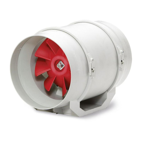
Montage- und Betriebsvorschrift ® MultiVent MV EC.. Serienteile zu MultiVent MV EC.. KAPITEL 2 Abb.5 SERIENTEILE UND ZUBEHÖR ë ò Gehäuse aus schlag- und korrosionsfestem Kunststoff ù Hochleistungslaufrad und ä Nachleitrad aus Kunststoff optimiert für hohe Druck- und Volumenleistung ë Klemmenkasten außen am ü... -
Page 6: Kapitel 3 Aufstellung/Montage
Montage- und Betriebsvorschrift ® MultiVent MV EC.. Montage KAPITEL 3 Die Ventilatoren werden serienmäßig als komplette Einheit, d.h. anschlussfertig geliefert. Sie können in beliebiger Achslage eingebaut werden – waagerecht, – senkrecht, – schräg (s. Abb. 11). Die Ventilatoren sind durch öffnen der AUFSTELLUNG/MONTAGE Spannbügel (s. -
Page 7: Wichtige Hinweise
Montage- und Betriebsvorschrift ® MultiVent MV EC.. Einbau Variable Positionierung des Ventilators bzw. Klemmenkasten möglich, je nach Einbaubedingung (s. Abb. 16). Abb.16 Wand – Körperschallübertragung Es ist darauf zu achten, dass Körperschallübertragungen auf Ge bäude und Rohrsystem vermieden werden! Die MultiVent ®... -
Page 8: Erstinbetriebnahme
Montage- und Betriebsvorschrift ® MultiVent MV EC.. Wird eine Fehlerstrom-Schutzeinrichtung in die Zuleitung des EC Ventilators verbaut, muss die Fehlerstrom-Schut- zeinrichtung die folgenden technischen Merkmale aufweisen: Typ A oder B mit einem Bemessungsdifferenzstrom von 30 mA. Der EC Ventilator hat einen Ableitstrom von <= 3,5 mA, ermittelt nach DIN EN 50178 Bild 4. KAPITEL 4 Erstinbetriebnahme Vor der Erstinbetriebnahme sind folgende Punkte zu prüfen:... -
Page 9: Kapitel 7 Schaltplan
Montage- und Betriebsvorschrift ® MultiVent MV EC.. KAPITEL 7 Abb.19 SS-1194 SCHALTPLÄNE MV EC 125 für MV EC.. MV EC 160 MV EC 200 MV EC 250 Wechselstrom, 1~, 230 V, 50 Hz... - Page 10 Montage- und Betriebsvorschrift ® MultiVent MV EC.. Abb.20 SS-1035...
- Page 11 Montage- und Betriebsvorschrift ® MultiVent MV EC.. Abb.21 SS-1195 MV EC 315...
- Page 12 ENGLISH Table of Contents CHAPTER 1 GENERAL INSTALLATION AND OPERATING INSTRUCTIONS ......Page 1 Important information .
-
Page 13: Important Information
If the preceding instructions are not observed all warranty claims and accommodation treatment are excluded. This also applies to any liability claims extended to the manufacturer. The use of accessories not offered or recommended by Helios is not permitted. Potential damages are not liable for warranty. -
Page 14: Sound Level
– Acoustics The noise data also refers to the above mentioned configuration. Adverse operating conditions etc. can lead to an increase of the given data. Noise problems can be eliminated by using flexible sound attenuators (see Helios accesso- ries). 1.10 Sound level The sound levels stated in the catalogue can differ considerably after installation as the sound pressure level depends on the absorption capacity of the room, the place of installation and other factors. -
Page 15: Multivent Mv Ec
Installation and Operating Instructions ® MultiVent MV EC.. MultiVent MV EC.. series parts CHAPTER 2 Fig.5 SERIES PARTS AND ACCESSORIES ë ò Casing made of impact and corrosion-resistant polymer ù High-performance impeller and ä Guide vane made of polymer optimized for high pressure and volume output ë... -
Page 16: Chapter 3 Mounting/Installation
Installation and Operating Instructions ® MultiVent MV EC.. Installation CHAPTER 3 The fans are delivered as complete units as standard, i.e. ready for installation. Installation is possible in every axle position – horizontal, vertical, diagonal (see Fig. 11). The fans are easy to remove by opening the clamp (see Fig. 12). The fan MOUNTING/ requires little space due to its low construction height, e.g. -
Page 17: Assembly
Installation and Operating Instructions ® MultiVent MV EC.. Assembly Variable positioning of the fan or terminal box is possible, depending on installation conditions (see Fig. 16). Fig.16 Wall – Structure-borne sound transmission It must be ensured that structure-borne sound transmission to the building and duct system is prevented! The MultiVent ®... -
Page 18: Initial Commissioning
Installation and Operating Instructions ® MultiVent MV EC.. If a residual current device is installed in the supply line of the EC fan, the residual current device must have the follo- wing technical features: Type A or B with a rated differential current of 30 mA. The EC fan has a leakage current of <= 3.5 mA, calculated according to DIN EN 50178 image 4. -
Page 19: Wiring Diagrams For Mv Ec
Installation and Operating Instructions ® MultiVent MV EC.. CHAPTER 7 Fig.19 SS-1194 WIRING DIAGRAMS MV EC 125 for MV EC.. MV EC 160 MV EC 200 MV EC 250 Alternating current, 1~, 230 V, 50 Hz... - Page 20 Installation and Operating Instructions ® MultiVent MV EC.. Fig.20 SS-1035...
- Page 21 Installation and Operating Instructions ® MultiVent MV EC.. Fig.21 SS-1195 MV EC 315...
- Page 22 FRANÇAIS Sommaire CHAPITRE 1. INFORMATIONS GÉNÉRALES SUR LE MONTAGE ET LE FONCTIONNEMENT ....Page 1 Informations importantes ..............Page 1 Mises en garde et consignes de sécurité...
-
Page 23: Chapitre 1. Informations Générales Sur Le Montage Et Le Fonctionnement
Si ces consignes ne sont pas respectées, la garantie s’annule. Idem pour les réserves constructeur. L’utilisation d’accessoires non conseillés ou proposés par Helios n’est pas permise. Les dégâts causés par cette mau- vaise utilisation ne sont pas inclus dans la garantie. -
Page 24: Turbine
Si la puissance utile de la tension de commande n’est pas suffisante, il est possible d’utiliser une alimentation externe 10 V DC (avec séparation galvanique du réseau). Pour une régulation par sondes de température, pression, vitesse, etc., utiliser le régulateur universel Helios EUR EC. Le câble de commande doit avoir la même isolation que le câble d‘alimentation. -
Page 25: Chapitre 2. Pièces De Série Et Accessoires
Notice de montage et d’utilisation ® MultiVent MV EC.. Pièces de série pour MultiVent MV EC ... CHAPITRE 2 Fig. 5 PIÈCES DE SÉRIE ET ACCESSOIRES ë ò Enveloppe synthétique, protégée contre les chocs et la corrosion ù Turbine haut rendement et ä... -
Page 26: Chapitre 3. Installation/Montage
Notice de montage et d’utilisation ® MultiVent MV EC.. Montage CHAPITRE 3 Les ventilateurs sont livrés de série en tant qu’unité complète, c’est-à-dire pré-câblés. Ils peuvent être montés dans la continuité de l’axe désirée : horizontal, vertical, oblique (voir fig. 11). Les ventilateurs se retirent facilement grâce aux INSTALLATION / arceaux de serrage (voir fig. -
Page 27: Installation
Notice de montage et d’utilisation ® MultiVent MV EC.. Installation Selon les conditions de montage, des positions alternatives du ventilateur et de la boîte à bornes (voir Fig. 16). Fig. 16 – Transmission de bruit Veiller à limiter la transmission de bruit dans le bâtiment et dans le système de gaines ! Les ventilateurs MultiVent ®... -
Page 28: Chapitre 4. Mise En Service
Notice de montage et d’utilisation ® MultiVent MV EC.. Si un dispositif de protection est intégré dans le raccordement du ventiltaeur EC, les spécificités suivantes doivent être prises en compte: Type A ou B avec un courant différentiel de 30 mA. Le ventilateur EC a un débit de fuite <= 3,5 mA, selon DIN EN 50178 Fig. -
Page 29: Schémas De Raccordement
Notice de montage et d’utilisation ® MultiVent MV EC.. CHAPITRE 7 Fig. 19 SS-1194 SCHÉMAS DE MV EC 125 RACCORDEMENT MV EC 160 Pour MV EC.. MV EC 200 MV EC 250 Courant alternatif, 1~, 230 V, 50 Hz... - Page 30 Notice de montage et d’utilisation ® MultiVent MV EC.. Fig. 20 SS-1035...
- Page 31 Notice de montage et d’utilisation ® MultiVent MV EC.. Fig. 21 SS-1195 MV EC 315...
- Page 32 HELIOS Ventilatoren GmbH + Co KG · Lupfenstraße 8 · 78056 VS-Schwenningen HELIOS Ventilateurs · Le Carré des Aviateurs · 157 avenue Charles Floquet · 93155 Le Blanc Mesnil Cedex CH HELIOS Ventilatoren AG · Tannstrasse 4 · 8112 Otelfingen GB HELIOS Ventilation Systems Ltd.