Riello RL 70 Manuel D'entretien
Masquer les pouces
Voir aussi pour RL 70:
- Instructions pour installation, utilisation et entretien (76 pages) ,
- Manuel d'entretien (52 pages) ,
- Instructions pour installation, utilisation et entretien (64 pages)
Table des Matières
Les langues disponibles
Les langues disponibles
Liens rapides
Istruzioni per installazione, uso e manutenzione
Manuel d'entretien
Installation, use and maintenance instructions
Bruciatore di gasolio
I
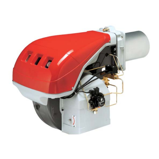
Brûleur fioul
F
Light oil burner
GB
Funzionamento bistadio
Fonctionnement à 2 allures
Two stage operation
CODICE - CODE
20044992
20042761
20058294
MODELLO
MODELE - MODEL
RL 70
RL 100
RL 100
TIPO - TYPE
44992X
42761X
58294X
20044173 (3) - 07/2012
Chapitres
Table des Matières

Manuels Connexes pour Riello RL 70


Sommaire des Matières pour Riello RL 70
- Page 1 Brûleur fioul Light oil burner Funzionamento bistadio Fonctionnement à 2 allures Two stage operation MODELLO CODICE - CODE TIPO - TYPE MODELE - MODEL 20044992 RL 70 44992X 20042761 RL 100 42761X 20058294 RL 100 58294X 20044173 (3) - 07/2012...
- Page 17 INDEX DONNÉES TECHNIQUES ......page 2 Modèles disponibles ........2 Accessoires .
-
Page 18: Données Techniques
DONNEES TECHNIQUES MODELE RL 70 RL 100 RL 130 TYPE 44992X 42761X - 58294X PUISSANCE 2e allure 474 - 830 711 - 1186 948 - 1540 Mcal/h 408 - 714 612 - 1020 816 - 1325 DEBIT kg/h 40 - 70... -
Page 19: Description Brûleur
être soulevée par des chariots transpalettes. Les dimensions d'encombrement de l'emballage sont reportées dans le tableau (B). • Le poids du brûleur avec son emballage est in- diqué dans le tab. (B). RL 70 1300 ENCOMBREMENT (C) - mesures indicatives RL 100 1300 L'encombrement du brûleur est indiqué... -
Page 20: Plages De Puissance
PLAGES DE PUISSANCE (A) Les brûleurs RL 70 - 100 - 130 peuvent fonction- D687 ner en deux modes: à une allure et à deux allures. Le DEBIT de 1re allure doit être choisi dans la plage A des diagrammes ci-contre. -
Page 21: Installation
INSTALLATION PLAQUE CHAUDIERE (A) Percer la plaque de fermeture de la chambre de combustion comme sur la fig.(A). La position des RL 70 275-325 M 12 trous filetés peut être tracée en utilisant l'écran thermique du brûleur. RL 100 275-325... -
Page 22: Montage Des Gicleurs
(F) avec le plan antérieur de la bride 5)(E). Exemple: RL 70 avec deux gicleurs de 6,0 GPH et pres- sion de la pompe 12 bar. Trouver dans le tab. (D) p. 5 le débit de deux gi- cleurs de 6,0 GPH: 25,5 + 25,5 = 51 kg/h. -
Page 23: Installation Hydraulique
à s'auto-alimenter parce que la distance et/ ou la différence de niveau avec la cuve sont su- périeures aux valeurs données dans le tableau. L (m) Légende RL 70 RL 100 - 130 H = Diff. niveau pompe-clapet de pied Ø (mm) Ø (mm) L = Longueur tuyau Ø... -
Page 24: Installation Électrique
INSTALLATION ELECTRIQUE RL 70 - RL 100 - RL 130 INSTALLATION ELECTRIQUE REALISEE USINE INSTALLATION ELECTRIQUE réalisée en usine SCHEMA (A) Brûleurs RL 70 - 100 - 130 • Les modèles RL 70 - 100 - 130 quittent l'usine prévus pour une alimentation électrique à... - Page 25 • Les modèles RL 70 - 100 - 130 quittent l’usine prévus pour l’alimentation électrique à 440 V. • Les modèles RL 70 - 100 - 130 ont été homo- logués pour fonctionner de façon intermittente. Cela veut dire qu’ils doivent s’arrêter selon les normes au moins 1 fois toutes les 24 heures pour permettre à...
-
Page 26: Amorçage Pompe
POMPE (A) POMPE SUNTEC E6 1 - Aspiration G 1/4" 2 - Retour G 1/4" 3 - Raccord manomètre G 1/8" 4 - Raccord vacuomètre G 1/8" 5 - Vis réglage pression 6 - Vis pour by-pass A - Débit min. a 12 bar de ression B - Plage de pression en refoulement C - Dépression max. -
Page 27: Réglage Brûleur
- vers la gauche (signe +) l'ouverture augmente. kg/h mbar kg/h mbar Exemple: RL 70 - Gicleur 1re allure 6,0 GPH: repère 2,3(A) correspondant au repère 1)(A). Le réglage fait, bloquer l'hexagone 2)(B) avec la (1) Avec obturateur 4)(C)p.5 reculé bague 1). -
Page 28: Fonctionnement Brûleur
FONCTIONNEMENT BRULEUR DEMARRAGE BRULEUR (A) - (B) Phases de démarrage avec temps progressifs en s.: • Fermeture télécommande TL. Après environ 3s: • 0 s : Le cycle de démarrage du coffret de sécurité est commencé. • 2 s : Démarrage moteur ventilateur. •... -
Page 29: Contrôles Finaux
CONTROLES FINAUX • Obscurcir la photorésistance et fermer les télé- commandes: le brûleur doit démarrer et se blo- quer 5 secondes environ après l’ouverture de la vanne de 1ère allure. • Eclairer la photorésistance et fermer les télé- commandes: le brûleur doit démarrer et, après environ 10 secondes, se bloquer.