Publicité

Les langues disponibles
  • FR

Les langues disponibles

Liens rapides

ISTRUZIONI PER L'USO
OPERATING INSTRUCTIONS
GEBRAUCHSANWEISUNG
MODE D'EMPLOI
INSTRUCCIONES DE USO
UP - -
UP
TOUCH
TOUCH
UP UP - -
ECO
ECO
04/21
cod. 4051361

Publicité

Table des Matières
loading

Sommaire des Matières pour Sabiana UP-TOUCH

  • Page 1 ISTRUZIONI PER L’USO OPERATING INSTRUCTIONS GEBRAUCHSANWEISUNG MODE D’EMPLOI INSTRUCCIONES DE USO UP - - TOUCH TOUCH UP UP - - 04/21 cod. 4051361...
  • Page 2 Italiano INSTALLAZIONE UNITA’ DI POTENZA UP-ECO PER COMANDO CB-E » Scopo SI RACCOMANDA DI LEGGERE ATTENTAMENTE QUESTE ISTRUZIONI PRIMA DI UTILIZZARE IL COMANDO. Il comando CB-E consente di poter accendere o spegnere l’apparecchio (Stand-by) e quindi Togliere sempre l’alimentazione di poter impostare facilmente la ventilazione elettrica prima di accedere alla mac- agendo in modo progressivo sulla velocità...
  • Page 3 Italiano 0-10V 3. Togliere la copertura della scheda di potenza. L1 - N La scheda viene fornita con i cavi motore collegati 5. Eseguire i collegamenti elettrici del motore 0-10V L1 - N ATTENZIONE!: COLLEGARE IL CAVO ”C” DELLA MESSA A TERRA AL RIVETTO DI TERRA POSTO SULLA SPALLA DELLA MACCHINA.
  • Page 4 Italiano » Montaggio del comando CB-E...
  • Page 5 Italiano » Schema Elettrico BLOCCARE Impianto senza valvola IL CAVO ALIMENTAZIONE UTILIZZANDO IL FERMACAVO CHRONOTHERMOSTAT REMOTE CB-E MOUNTED CONTROL Contatto 0/DI1: Con CTR rimuovere Jumper MC2. CLOSE POWER UNIT LEGENDA: Collegamento attuatore B1 = Sonda aria T1 valvola acqua B2 = Sonda change-over T2 B3 = Sonda di minima T3 POWER UNIT M = Motoventilatore...
  • Page 6 Italiano INSTALLAZIONE UNITA’ DI POTENZA UP-TOUCH PER COMANDO CB-Touch si voglia privilegiare il funzionamento silenzioso. » Scopo Collegando la sonda di minima (accessorio sonda T3, SI RACCOMANDA DI LEGGERE ATTENTAMENTE posta tra le alette della batteria di scambio termico), nel QUESTE ISTRUZIONI PRIMA DI UTILIZZARE IL ciclo invernale, il ventilatore entrerà...
  • Page 7 Italiano 0-10V L1 - N 3. Togliere la copertura della scheda di potenza La scheda viene fornita con i cavi motore collegati 5. Eseguire i collegamenti elettrici del motore 0-10V L1 - N ATTENZIONE!: COLLEGARE IL CAVO ”C” DELLA MESSA A TERRA AL RIVETTO DI TERRA POSTO SULLA SPALLA DELLA MACCHINA.
  • Page 8 Italiano » Montaggio del comando CB-Touch...
  • Page 9 Italiano » Schema Elettrico BLOCCARE IL CAVO ALIMENTAZIONE UTILIZZANDO IL FERMACAVO Impianto senza valvole CB-TOUCH MOUNTED CONTROL POWER UNIT CTRL Collegamento attuatore LEGENDA: valvola acqua B1 = Sonda aria T1 B2 = Sonda change-over T2 POWER UNIT B3 = Sonda di minima T3 M = Motoventilatore Q1 = Interruttore di manovra sezionatore 0-DI1 = Contatto pulito...
  • Page 10 Italiano » Impostazioni dip di configurazione N° DIP DEFAULT Ventilazione contemporanea con la Ventilazione continua valvola senza post ventilazione e on/off sulle valvole Slave Master ---- ---- ---- ---- » Funzione dei contatti ausiliari » Scheda Elettronica 0-DI1 RS485 0/10V POWER UNIT Boiler Chiller CTRL...
  • Page 11 Italiano » Accessori • ISTRUZIONE PER L’INSTALLAZIONE DELLA SONDA ARIA T1 ATTENZIONE: Per un corretto funzionamento della sonda eseguire l’installazione come indicato nelle istruzioni. • Collegare la sonda aria al connettore T1 sulla scheda di potenza CFF; • Posizionare la sonda in ripresa nella sede dedicata...
  • Page 12 Italiano • ISTRUZIONE PER L’INSTALLAZIONE DELLA SONDA ARIA T3 Se si utilizza la sonda di minima, bisogna procedere nel seguente modo: Inserire la sonda di minima tra le alette della batte- ria tenendola leggermente inclinata verso il basso. Collegare la sonda al connettore T3 della scheda di potenza.
  • Page 13 Italiano MANUALE D’USO UNITA’ DI POTENZA UP-TOUCH PER COMANDI A PARETE » Accessorio WM-AU . 9066632) AUTO AUTO ° AUTO AUTO ° h = 150 cm WM-AU è un comando per installazione a parete. Le funzioni del comando sono: • Accensione e spegnimento del ventilconvettore.
  • Page 14 Italiano 135 mm 28 mm AUTO AUTO ° Effettuare i collegamenti elettrici come riportato nel presente manuale. DIN 503...
  • Page 15: Collegamenti Elettrici

    Italiano COLLEGAMENTI ELETTRICI Fig.”B” Il pannello comandi deve essere collegato elettri- camente alla scheda di potenza posta all’interno dell’apparecchiatura elettrica dell’unità rispettando la corrispondenza della numerazione comune ad entrambe le schede. Utilizzare 3 conduttori con sezione 0,5 mm NOTA: La lunghezza del cavo di collegamento non AUTO AUTO deve essere superiore ai 20 metri.
  • Page 16: Segnalazione Allarmi

    Italiano Fig.”D” Fig.”F” AUTO AUTO AUTO ° AUTO AUTO ° Selezione velocità ventilatore (Fig. “D”): Risparmio Energetico (Fig. ”F”) • Premendo il pulsante indicato selezionare la velo- La funzione energy saving viene attivata / disattivata con la cità ventilatore desiderata: pressione del pulsante 6 e segnalata tramite l’accensione o lo spegnimento del led 6a.
  • Page 17: Installazione Del Comando

    60 mm 84 mm Italiano » Accessorio TM-B . 9066331E) AUTO INSTALLAZIONE DEL COMANDO ATTENZIONE! Per eseguire i collegamenti elettrici al comando T–MB occorre rimuovere la protezione isolante dal mor- setto. Una volta eseguiti i collegamenti elettrici riposizionare la protezione come da Fig. 2. Rimontare la parte frontale del comando inserendo prima le due linguette presenti nella parte inferiore;...
  • Page 18 Italiano UTILIZZO DEL COMANDO Fig.”C” Fig.”A” ° Selezione modalità (Fig. “C”): • Premendo il pulsante “M” selezionare la modalità di On/Off (Fig. “A”): funzionamento voluta: • Premendo il tasto ON/OFF il comando viene acceso. − viene impostata la funzione raffreddamento. •...
  • Page 19: Impostazione Orologio

    Italiano IMPOSTAZIONE OROLOGIO TIMER Fig.”E” Fig.”F” > 2 sec. • Premere il tasto “M”: il simbolo della modalità ini- 1) Attivazione / Disattivazione (Fig. “F”): zierà a lampeggiare. • Premere il tasto “M”; il simbolo della modalità • Premere i tasti (+) o (-), fino alla selezione del sim- di funzionamento inizierà...
  • Page 20 Italiano Fig.”G” 2) Programmazione (Fig. “G”): • Premere il tasto “M”; il simbolo della modalità di funzionamento inizierà a lampeggiare. • Premere il tasto (+) o (-) fino alla selezione del sim- bolo orologio “ ”; confermare con il tasto “M”. •...
  • Page 21: Risparmio Energetico

    Italiano RISPARMIO ENERGETICO FUNZIONI PER IL SERVICE > 3 sec. Con questo menù è possibile verificare alcuni dei parametri del comando (valore delle sonde, eventuali allarmi). ° Premere i tasti “+” e “-” contemporaneamente per 3 secondi con il comando in “OFF”. Scegliere il parametro desiderato premendo i tasti “+”...
  • Page 22: Altre Funzioni

    Italiano FUNZIONI PER IL FACTORY Questo menù consente di modificare i parametri di funzionamento del ter- mostato, del motore elettronico e di altri vari parametri (ciclo pompa, RESET). Con il comando in “OFF” premere i tasti M e Fan contemporaneamente per 3 secondi.
  • Page 23: Funzionamento Master&Slave

    Italiano » Funzionamento Master&Slave È possibile collegare più apparecchi fra loro e control- Utilizzate sempre un unico cavo per collegare fra di loro le larli simultaneamente trasmettendo le impostazioni dal singole unità; comando (accessorio optional) ad un’unica unità MASTER. - non serrare eccessivamente i conduttori sotto i morsetti Il funzionamento di ogni singolo apparecchio dipenderà...
  • Page 24: Messa A Terra Della Rete

    Italiano » Master&Slave con comando T-MB Nota: Il ventilcovettore MASTER dovrà avere il Dip 2 in posizione OFF, mentre tutti gli apparecchi collegati come SLAVE dovranno avere il Dip 2 in posizione ON. Ogni volta che si crea una rete seriale è importante defi- nirne l’inizio e la fine chiudendo il Jumper MC4 sulla prima e sull’ultima unità...
  • Page 25 English UP-ECO POWER UNIT INSTALLATION for CB-E control » Purpose WE RECOMMEND THAT YOU READ THESE INSTRUCTIONS CAREFULLY BEFORE USING THE CONTROL. The CB-E control allows the device to be switched on or off (Stand-by) and therefore to Always disconnect the electrical easily set the ventilation by progressively acting power supply before opening the unit.
  • Page 26 English 3. Remove the power board cover 0-10V The electronic board is supplied with the cables con- nected L1 - N Do the electrical motor connections 0-10V L1 - N WARNING!: CONNECT THE GROUNDING CABLE "C" TO THE GROUND RIVET ON THE SHOULDER OF THE MACHINE.
  • Page 27 English » Installation of the CB-E control...
  • Page 28 English » Wiring Diagram BLOCK THE SUPPLY CABLE WITH Installation without valve THE CABLE FASTENER CHRONOTHERMOSTAT REMOTE CB-E MOUNTED CONTROL Contact 0/DI1: With CTR remove the MC2 Jumper. CLOSE POWER UNIT KEY: Water valve actuator connection B1 = Air probe T1 B3 = Minimum probe T3 M = Fan motor POWER UNIT...
  • Page 29 English UP-TOUCH POWER UNIT INSTALLATION FOR CB-Touch control or the minimum speed when you want to privilege » Purpose silent operation. WE RECOMMEND THAT YOU READ THESE By connecting the minimum probe (T3 accessory INSTRUCTIONS CAREFULLY BEFORE USING THE probe, located between the fins of the heat exchange CONTROL.
  • Page 30 English 0-10V 3. Remove the power board cover L1 - N The electronic board is supplied with the cables connected. 5. Do the electrical motor connections 0-10V L1 - N WARNING!: CONNECT THE GROUNDING CABLE "C" TO THE GROUND RIVET ON THE SHOULDER OF THE MACHINE.
  • Page 31 English » Installation of the CB-Touch control...
  • Page 32 English » Wiring Diagram BLOCK THE SUPPLY CABLE WITH THE CABLE FASTENER Installation without valve CB-TOUCH MOUNTED CONTROL POWER UNIT CTRL Water valve actuator KEY: connection B1 = Air probe T1 B2 = Changeover probe T2 POWER UNIT B3 = Minimum probe T3 M = Fan motor Q1 = Disconnector control switch 0-DI1 = ON/OFF Clean contact outside the...
  • Page 33 English » Configuration dip switch settings DIP NO. DEFAULT Simultaneous ventilation with the Continuous ventilation and on/off valve without post-ventilation on the valves Slave Master ---- ---- ---- ---- » Function of auxiliary contacts » Electronic card 0-DI1 RS485 0/10V POWER UNIT Boiler Chiller CTRL...
  • Page 34: Accessories

    English » Accessories • INSTRUCTION FOR THE INSTALLATION OF THE T1 AIR PROBE WARNING: For a correct operation of the probe perform the installation as indicated in the instructions. • Connect the air probe to the T1 connector on the CFF power board; •...
  • Page 35 English • INSTRUCTION FOR THE INSTALLATION OF THE T3 AIR PROBE If the minimum probe is used, proceed as follows: insert the minimum probe between the coil fins keeping it slightly tilted downwards. Connect the probe to the T3 connector on the power board. •...
  • Page 36 English UP-TOUCH POWER UNIT HANDBOOK FOR WALL CONTROLS » WM-AU accessory 9066632) AUTO AUTO ° AUTO AUTO ° h = 150 cm WM-AU is a control for wall installation. The functions of the control are: • Switching the fan coil unit on and off.
  • Page 37 English 135 mm 28 mm AUTO AUTO ° Make the electrical connections as described in this manual. DIN 503...
  • Page 38: Electrical Connections

    English ELECTRICAL CONNECTIONS Fig."B" The control panel must be electrically connected to the power board located inside the device electrical equipment, respecting the correspondence of the numbering common to both boards. Use 3 leads with 0.5 mm² section. NOTE: The length of the connection cable must not exceed 20 metres.
  • Page 39: Alarm Signalling

    English Fig."D" Fig."F" AUTO AUTO AUTO ° AUTO AUTO ° Fan speed selection (Fig. "D"): Energy Saving (Fig. "F") • Press the indicated button to select the desired fan The energy saving function is activated / deactivated by speed: pressing button 6 and signalled by the switching on or off of LED 6a.
  • Page 40 60 mm 84 mm English » TM-B accessory 9066331E) AUTO INSTALLATION OF THE CONTROL WARNING! To make the electrical connections to the T-MB control remove the insulation protection from the terminal. Once the electrical connections have been made, reposition the protection as shown in Fig. 2. Reassemble the front part of the control by first inserting the two tabs at the bottom;...
  • Page 41 English USE OF THE CONTROL Fig."C" Fig."A" ° Mode selection (Fig. "C"): • Press the "M" button to select the desired On/Off (Fig. "A"): operation mode: • By pressing the ON/OFF button the control is switched on. the cooling function is set. •...
  • Page 42: Clock Setting

    English CLOCK SETTING TIMER Fig."E" Fig."F" > 2 sec. • Press the "M" button: the mode symbol will start 1) Activation / Deactivation (Fig. "F"): flashing. • Press the "M" button; the operation mode symbol • Press the (+) or (-) buttons until the clock symbol " "...
  • Page 43 English Fig."G" 2) Programming (Fig. "G"): • Press the "M" button; the operation mode symbol will start flashing. • Press the (+) or (-) button until the clock symbol " " is selected; confirm with the "M" button. • Press the "+" button twice; "Prd" will display. Press the "M"...
  • Page 44: Energy Saving

    English ENERGY SAVING SERVICE FUNCTIONS > 3 sec. With this menu you can check some of the control parameters (probes value, possible alarms). ° Press the "+" and "-" buttons simultaneously for 3 seconds with the control in "OFF". Select the desired parameter by pressing the "+" or "-" buttons and confirm with the "M"...
  • Page 45 English FUNCTIONS FOR THE FACTORY This menu allows you to modify the operating parameters of the thermostat, the electronic motor and other parameters (pump cycle, RESET). With the control in "OFF" press the M and Fan buttons simultaneously for 3 seconds. Select the parameter to be changed by pressing the "+"...
  • Page 46: Master&Slave Operation

    English » Master&Slave operation It is possible to connect several devices to each other Always use a single cable to connect the individual units and control them simultaneously by transmitting the together; settings from the control (optional accessory) to a single - do not overtighten the leads under the terminal MASTER unit.
  • Page 47 English » Master&Slave with T-MB control Note: The MASTER fan coil unit must have Dip switch 2 in OFF position, while all the devices connected as SLAVE must have Dip switch 2 in ON position. Every time a serial network is created it is important to define its beginning and end by closing the MC4 Jumper on the first and last connected unit.
  • Page 48: Installation De L'unité D'alimentation Up-Eco Pour Commande Cb-E

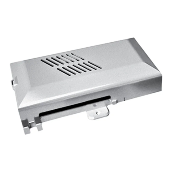
    Français INSTALLATION DE L’UNITÉ D’ALIMENTATION UP-ECO POUR COMMANDE CB-E » Objectif IL EST RECOMMANDÉ DE LIRE ATTENTIVEMENT CE MODE D’EMPLOI AVANT D’UTILISER LA COM- MANDE. La commande CB-E permet d’activer ou d’éteindre l’appareil (veille) et donc pouvoir ré- Toujours couper l’alimentation élec- gler facilement l’aération en agissant progressi- trique avant d’accéder à...
  • Page 49 Français 3. Retirer le couvercle de la carte d’alimentation. 0-10V La carte électronique est livrée avec les câble connec- L1 - N tés. 5. Effectuer les branchements électriques du moteur. 0-10V L1 - N ATTENTION  ! BRANCHER LE CÂBLE «  C  » DE LA MISE À...
  • Page 50 Français » Montage de la commande CB-E...
  • Page 51: Raccordement Actionneur Vanne Eau

    Français » Schéma électrique BLOQUER Installation sans vanne LE CABLED’ALIMENTATION AU MOYEN DU SERRE-CABLE CHRONOTHERMOSTAT REMOTE CB-E MOUNTED CONTROL Contact 0/DI1: Avec CTR enlever le cavalier MC2. CLOSE POWER UNIT LÉGENDE : Raccordement actionneur B1 = Sonde air T1 vanne eau B3 = Sonde minimale T3 M = Motoventilateur Q1 = Interrupteur de manœuvre...
  • Page 52: Installation De L'unité D'alimentation Up-Touch Pour Commande Cb

    Français INSTALLATION DE L’UNITÉ D’ALIMENTATION UP-TOUCH POUR COMMANDE CB-Touch En branchant la sonde minimale (sonde accessoire T3, » Objectif placée entre les ailettes de la batterie d’échange ther- IL EST RECOMMANDÉ DE LIRE ATTENTIVEMENT mique), pendant le cycle d’hiver, le ventilateur ne se CE MODE D’EMPLOI AVANT D’UTILISER LA COM-...
  • Page 53 Français 0-10V 3. Retirer le couvercle de la carte d’alimentation. L1 - N La carte électronique est livrée avec les câble connec- tés. 5. Effectuer les branchements électriques du moteur. 0-10V L1 - N 5. ATTENTION ! : BRANCHER LE CÂBLE « C » DE LA MISE À...
  • Page 54 Français » Montage de la commande CB-Touch...
  • Page 55: Schéma Électrique

    Français » Schéma électrique BLOQUER LE CABLED’ALIMENTATION AU Installation sans vanne MOYEN DU SERRE-CABLE CB-TOUCH MOUNTED CONTROL POWER UNIT CTRL Raccordement actionneur LÉGENDE : vanne eau B1 = Sonde air T1 B2 = Sonde change-over T2 POWER UNIT B3 = Sonde minimale T3 Motoventilateur Q1 = Interrupteur de manœuvre...
  • Page 56 Français » Paramètres dip de configuration N° DIP DÉFAUT Aération simultanée avec la vanne Aération continue sans post-aération et on/off sur les vannes Slave Master ---- ---- ---- ---- » Carte électronique » Fonction des contacts auxiliaires 0-DI1 RS485 0/10V POWER UNIT Boiler Chiller CTRL...
  • Page 57: Accessoires

    Français » Accessoires • INSTRUCTION POUR L’INSTALLATION DE LA SONDE À AIR T1 ATTENTION : Pour le bon fonctionnement de la sonde, effectuer l’installation comme indiqué dans les instructions. • Brancher la sonde à air au connecteur T1 sur la carte d’alimentation CFF ; •...
  • Page 58: Sonda T2 Par Change-Over (En Option)

    Français • INSTRUCTION POUR L’INSTALLATION DE LA SONDE À AIR T3 Si la sonde minimale est utilisée, procéder comme suit : Insérer la sonde minimale entre les ailettes de la bat- terie tout en la maintenant légèrement inclinée vers le bas. Brancher la sonde sur le connecteur T3 de la carte d’alimentation.
  • Page 59 Français MANUEL D’UTILISATION UNITÉ D’ALIMENTATION UP-TOUCH POUR COMMANDES AU MUR » Accessoire WM-AU 9066632) AUTO AUTO ° AUTO AUTO ° WM-AU est une commande pour installation au mur. h = 150 cm Les fonctions de la commande sont les suivantes : •...
  • Page 60 Français 135 mm 28 mm AUTO AUTO ° Effectuer les branchements électriques comme décrit dans ce manuel. DIN 503...
  • Page 61: Branchements Électriques

    Français BRANCHEMENTS ÉLECTRIQUES Fig. « B » Le panneau de commande doit être branché électri- quement à la carte d’alimentation située à l’intérieur de l’équipement électrique de l’unité, en respectant la correspondance de la numérotation commune aux deux cartes. Utiliser 3 conducteurs de 0,5 mm de section.
  • Page 62: Verrouillage/Déverrouillage Du Clavier

    Français Fig. « D » Fig. « F » AUTO AUTO AUTO ° AUTO AUTO ° Sélection de la vitesse du ventilateur (Fig. « D ») : Économie d’énergie (Fig. « F ») • Appuyer sur le bouton indiqué pour sélectionner la La fonction d’économie d’énergie est activée/désacti- vitesse du ventilateur souhaitée : vée en appuyant sur le bouton 6 et signalée par l’allu- mage ou l’extinction de la LED 6a.
  • Page 63: Installation De La Commande

    60 mm 84 mm Français » Accessoire TM-B 9066331E) CodE AUTO INSTALLATION DE LA COMMANDE ATTENTION ! Pour effectuer les branchements électriques à la commande T–MB la protection isolante de la borne doit être retirée. Une fois les branchements électriques réalisés, repo- sitionner la protection selon la Fig.
  • Page 64 Français UTILISATION DE LA COMMANDE Fig. « C » Fig. « A » ° Sélection du mode (Fig. « C ») : • Appuyer sur le bouton « M » pour sélectionner le On/Off (Fig. « A ») : mode de fonctionnement souhaité : • En appuyant sur la touche ON/OFF, la commande s’allume.
  • Page 65: Réglage Horloge

    Français RÉGLAGE HORLOGE COMPTEUR HORAIRE Fig. « E » Fig. « F » > 2 sec. 1) Activation / Désactivation (Fig. « F ») : • Appuyer sur la touche « M » : le symbole du mode se met à clignoter. • Appuyer sur la touche « M » ; le symbole du mode •...
  • Page 66 Français Fig. « G » 2) Programmation (Fig. « G ») : • Appuyer sur la touche « M » ; le symbole du mode de fonctionnement se met à clignoter. • Appuyer sur la touche (+) ou (-) jusqu’à ce que le symbole de l'horloge «   » soit sélectionné ; confir- mer avec la touche « M ».
  • Page 67: Économie D'énergie

    Français ÉCONOMIE D’ÉNERGIE FONCTIONS POUR LE SERVICE > 3 sec. Ce menu permet de vérifier certains des paramètres de la commande (valeur des sondes, alarmes éven- tuelles). ° Appuyer sur les touches « + » et « - » simultanément pendant 3 secondes avec la commande en « OFF ». Sélectionner le paramètre souhaité...
  • Page 68: Fonctions Pour Le Factory

    Français FONCTIONS POUR LE FACTORY Ce menu permet de modifier les paramètres de fonctionnement du ther- mostat, du moteur électronique et d’autres paramètres divers (cycle pompe, REMISE À ZÉRO). Avec la commande en « OFF » appuyer simultanément sur les touches M et Fan pendant 3 secondes.
  • Page 69: Fonctionnement Master&Slave

    Français » Fonctionnement Master&Slave Il est possible de connecter plusieurs appareils entre eux Utiliser toujours un seul câble pour brancher les différentes et de les commander simultanément en transmettant les unités entre elles ; réglages de la commande (accessoire en option) à une seule –...
  • Page 70: Master&Slave Avec Commande T-Mb

    Français » Master&Slave avec commande T-MB Remarque : Le ventilo-convecteur MASTER devra avoir le Dip 2 en position OFF, tandis que tous les appareils branchés en tant que SLAVE doivent avoir le Dip 2 en position ON. Chaque fois que vous créez un réseau série, il est impor- tant de définir le début et la fin en fermant le cavalier MC4 sur la première et la dernière unité...
  • Page 71 Deutsch INSTALLATION LEISTUNGSEINHEIT UP-ECO FÜR STEUERUNG CB-E » Zweck ES WIRD EMPFOHLEN, DIESE ANWEISUNG VOR DER VERWENDUNG DER STEUERUNG SORGFÄLTIG ZU LESEN. Die Steuerung CB-E ermöglicht es, das Gerät ein- oder auszuschalten (Stand-by) und Vor der Inbetriebnahme der Maschi- somit auf einfache Weise den Lüftbetrieb ne muss immer die Stromversorgung einzustellen, indem sie progressiv auf die getrennt werden.
  • Page 72 Deutsch 3. Entfernen Sie die Leistungsplatinenabdeckung 0-10V Elektronikplatine wird geliefert angeschlossenen Kabeln. L1 - N 5. Elektroanschlüsse vom Motor ausführen 0-10V L1 - N ACHTUNG! VERBINDEN SIE DAS ERDUNGSKABEL „C“ MIT DEM ERDUNGSNIET AM SCHULTERTEIL DER MASCHINE. 4. Befestigen Sie die Leistungsplatine mit den 2 mitgelieferten selbstschneidende Schrauben.
  • Page 73 Deutsch » Montage der CB-E-Steuerung...
  • Page 74 Deutsch » Schaltplan DIE NETZKABEL MITHILFE DES KABELBINDERS Installation ohne Ventile BLOCKIEREN CHRONOTHERMOSTAT REMOTE CB-E MOUNTED CONTROL Kontakt 0/DI1: Mit CTR das Jumper MC2 abnehmen. CLOSE POWER UNIT LEGENDE: Anschluss Stellmotor Wasserventil B1 = Luftsonde T1 B3 = Mindeststandsonde T3 M = Motorventilator POWER UNIT Q1 = Trennschalter...
  • Page 75 Deutsch INSTALLIERUNG LEISTUNGSEINHEIT UP-TOUCH FÜR STEUERUNG CB-Touch (Zubehörsonde T3, die zwischen den Lamellen » Zweck des Wärmetauschers angebracht wird) wird der VOR DEM EINSATZ DER STEUERUNG UNBEDINGT Ventilator während des Winterzyklus nur dann in DIESE ANWEISUNGEN LESEN. Betrieb genommen, wenn die Wassertemperatur höher als 30 °C ist, wodurch verhindert wird, dass...
  • Page 76 Deutsch 0-10V 3. Entfernen Sie die Leistungsplatinenabdeckung L1 - N Elektronikplatine wird geliefert angeschlossenen Kabeln. 5. Elektroanschlüsse vom Motor ausführen 0-10V L1 - N ACHTUNG! VERBINDEN ERDUNGSKABEL „C“ ERDUNGSNIET AM SCHULTERTEIL DER MASCHINE. 4. Befestigen Sie die Leistungsplatine mit den 2 mitgelieferten selbstschneidenden Schrauben.
  • Page 77 Deutsch » Montage der CB-Touch-Steuerung...
  • Page 78 Deutsch » Schaltplan DIE NETZKABEL MITHILFE DES KABELBINDERS BLOCKIEREN Installation ohne Ventile CB-TOUCH MOUNTED CONTROL POWER UNIT CTRL Anschluss Stellmotor LEGENDE: Wasserventil B1 = Luftsonde T1 POWER UNIT B2 = Change-over-Sonde T2 B3 = Mindeststandsonde T3 M = Motorventilator Q1 = Trennschalter 0-DI1 = Sauberer Kontakt On/Off außen Thermostat-Zeitschaltuhr (Mc2 offen) BO = Sauberer Kontakt ( Max 1 A)
  • Page 79 Deutsch » Konfigurations-Dip-Einstellungen DIP-NR. FAULT Gleichzeitige Belüftung mit dem Kontinuierliche und ON/OFF-Be- Ventil ohne Nachbelüftung lüftung auf den Ventilen Slave Master ---- ---- ---- ---- » Elektronische Leiterplatte » Funktion der Hilfskontakte 0-DI1 RS485 0/10V POWER UNIT Boiler Chiller CTRL Die elektronische Karte verfügt über 2 SPST-Relais mit Kontakttyp NO (Schließkontakt) für die externe Zustimmung (freie Spannung DO - Digital Output) für:...
  • Page 80 Deutsch » Zubehör • ANWEISUNG FÜR DIE INSTALLATION DER LUFTSONDE T1 ACHTUNG: Für den korrekten Betrieb der Sonde führen Sie die Installation wie in der Anweisung angegeben durch. - Schließen Sie die Luftsonde an den Anschluss T1 auf der CFF-Leistungsplatine an; •...
  • Page 81 Deutsch • ANWEISUNG FÜR DIE INSTALLATION DER LUFTSONDE T3 Wenn die Mindeststandsonde verwendet wird, gehen Sie wie folgt vor: Führen Sie die Mindeststandsonde zwischen die Flügel der Batterie ein, während Sie sie leicht nach unten geneigt halten. Schließen Sie die Sonde an den T3-Stecker auf der Leistungsplatine an.
  • Page 82: Wm-Au-Zubehör

    Deutsch BETRIEBSANWEISUNG LEISTUNGSEINHEIT UP-TOUCH FÜR WANDSTEUERGERÄTE » WM-AU-Zubehör 9066632) AUTO AUTO ° AUTO AUTO ° h = 150 cm WM-AU ist eine Steuerung für die Wandinstallation. Die Funktionen der Steuerung sind: • Ein- und Ausschalten des Ventilatorkonvektors • Einstellung der gewünschten Raumtemperatur (SET).
  • Page 83 Deutsch 135 mm 28 mm AUTO AUTO ° Nehmen Sie die elektrischen Anschlüsse wie in dieser Betriebsanweisung beschrieben vor. DIN 503...
  • Page 84: Elektrische Anschlüsse

    Deutsch ELEKTRISCHE ANSCHLÜSSE Abb. „B“ Bedienfeld muss elektrisch Leistungsplatine verbunden sein, die sich im Inneren der elektrischen Ausrüstung des Geräts befindet, wobei die Entsprechung der beiden Platinen gemeinsamen Nummerierung zu beachten ist. Verwenden Sie 3 Leiter mit 0,5 mm² Querschnitt. ANMERKUNG: Die Länge des Anschlusskabels darf 20 AUTO AUTO...
  • Page 85 Deutsch Abb. „D“. Abb. „F“. AUTO AUTO AUTO ° AUTO AUTO ° Auswahl der Ventilatorgeschwindigkeit (Abb. „D“): Energieeinsparung (Abb. „F“) • Drücken Sie die angegebene Taste, um Die Energiesparfunktion wird durch Drücken der Taste 6 die gewünschte Ventilatorgeschwindigkeit aktiviert/deaktiviert und durch Ein- oder Ausschalten der auszuwählen: LED 6a signalisiert.
  • Page 86 60 mm 84 mm Deutsch » Zubehör TM-B 9066331E) AUTO INSTALLIERUNG DER STEUERUNG ACHTUNG! Elektrischen Verbindungen zur Steuerung T–MB Der Isolationsschutz muss von der Klemme entfernt werden. Sobald die elektrischen Verbindungen hergestellt sind, positionieren Sie den Schutz wie gezeigt - siehe Abb.
  • Page 87 Deutsch BENUTZUNG DER STEUERUNG Abb. „C“ Abb. „A“ ° Auswahl des Modus (Abb. „C“): On/Off (Abb. „A“): • Die „M“-Taste, um die gewünschte Betriebsart zu wählen: • Durch Druck der Taste ON/OFF wird die Steuerung eingeschaltet. − Es wird die Kühlfunktion eingestellt. •...
  • Page 88: Einstellung Der Uhrzeit

    Deutsch EINSTELLUNG DER UHRZEIT ZEITSCHALTUHR Abb. „E“. Abb. „F“. > 2 sec. • -Drücken Sie die Taste „M“: Das Modussymbol 1) Aktivierung/Deaktivierung (Abb. „F“): beginnt zu blinken. • Drücken Sie die Taste „M“; das Betriebsmodisymbol • Drücken Sie die Tasten (+) oder (-), bis das beginnt zu blinken.
  • Page 89 Deutsch Abb. „G“. 2) Programmierung (Abb. „G“): • Drücken Sie die Taste „M“; das Betriebsmodisymbol beginnt zu blinken. • Drücken Sie die Taste (+) oder (-) bis das Uhrsymbol „ ” angewählt ist; bestätigen Sie mit der Taste „M“. • Drücken Sie zweimal die Taste „+“; „Prd“ erscheint auf dem Display.
  • Page 90: Service-Funktionen

    Deutsch ENERGIEEINSPARUNG SERVICE-FUNKTIONEN > 3 sec. Mit diesem Menü ist es möglich, einige der Parameter des Befehls zu überprüfen (Sondenwert, mögliche Alarme). ° Drücken Sie die Tasten „+“ und „-“ gleichzeitig 3 Sekunden lang, wobei der Befehl auf „OFF“ steht. Wählen Sie den gewünschten Parameter durch Druck der Taste „+“...
  • Page 91 Deutsch FACTORY-FUNKTIONEN Dieses Menü ermöglicht die Änderung der Betriebsparameter Thermostats, elektronischen Motors anderer verschiedener Parameter (Pumpenzyklus, RESET). Mit dem Befehl auf „OFF“ die Tasten M und Lüfter gleichzeitig für 3 Sekunden drücken. > 3 sec. Wählen Sie den zu ändernden Parameter durch Drücken der Tasten „+“ oder „-“...
  • Page 92: Master&Slave-Betrieb

    Deutsch » Master&Slave-Betrieb Es ist möglich, mehrere Geräte miteinander zu verbinden - Spleißen Sie keine Kabelverbindungen. und sie gleichzeitig zu steuern, indem die Einstellungen Verwenden Sie immer nur ein einziges Kabel, um die von der Steuerung (optionales Zubehör) an ein einziges einzelnen Einheiten miteinander zu verbinden;...
  • Page 93 Deutsch » Master&Slave mit T-MB-Steuerung Anmerkung: Bei der MASTER-Ventilatorkonvektoreinheit muss sich Dip 2 in der Position OFF befinden, während bei allen als SLAVE angeschlossenen Geräten Dip 2 in der Position ON sein muss. Jedes Mal, wenn Sie ein serielles Netzwerk erstellen, ist es wichtig, dessen Anfang und Ende durch Schließen des MC4-Jumpers an der ersten und letzten CHIUSO...
  • Page 94 Español INSTALACIÓN DE LA UNIDAD DE POTENCIA UP-ECO CON MANDO CB-E » Propósito SE RECOMIENDA LEER ATENTAMENTE ESTAS INSTRUCCIONES ANTES DE UTILIZAR EL MANDO. El mando CB-E permite encender o apagar la uni- dad (espera) y programar fácilmente la ventila- Desconecte siempre la alimenta- ción mediante el ajuste gradual de la velocidad ción eléctrica antes de acceder a la...
  • Page 95 Español 3. Retire la cubierta de la placa de alimentación. La tarjeta electrónica se suministra con los cables co- 0-10V nectados L1 - N 5. Haga las conexiones eléctricas del motor 0-10V L1 - N ATENCIÓN: CONECTE EL CABLE "C" DE PUESTA A TIERRA AL REMACHE DE TIERRA SITUADO EN LA PARTE TRASERA DE LA MÁQUINA.
  • Page 96 Español » Montaje del mando CB-E...
  • Page 97: Esquema Eléctrico

    Español BLOQUEAR EL CABLE » Esquema eléctrico D’ALIMENTACIÓN MEDIANTE DEL ANCLAJE Instalación sin válvula PARA CABLE CHRONOTHERMOSTAT REMOTE CB-E MOUNTED CONTROL Contacto 0/DI1: Por medio del CTR quitar el jumper MC2. CLOSE POWER UNIT LEYENDA: Conexión actuador válvula agua = Sensor de aire T1 = Sensor de mínimo T3 = Motoventilador POWER UNIT...
  • Page 98 Español INSTALACIÓN DE LA UNIDAD DE POTENCIA UP-TOUCH CON MANDO CB-Touch Conectando el sensor de mínimo (sensor au- » Propósito xiliar T3, colocado entre las aletas de la ba- SE RECOMIENDA LEER ATENTAMENTE ESTAS tería de intercambio térmico) durante el ci- INSTRUCCIONES ANTES DE UTILIZAR EL MANDO.
  • Page 99 Español 0-10V L1 - N 3. Retire la cubierta de la placa de alimentación. La tarjeta electrónica se suministra con los cables co- nectados. 5. Haga las conexiones eléctricas del motor 0-10V L1 - N ATENCIÓN: CONECTE EL CABLE "C" DE PUESTA A TIERRA AL REMACHE DE TIERRA SITUADO EN LA PARTE TRASERA DE LA MÁQUINA.
  • Page 100 Español » Montaje del mando CB-Touch...
  • Page 101 Español BLOQUEAR EL CABLE » Esquema eléctrico D’ALIMENTACIÓN MEDIANTE DEL ANCLAJE Instalación sin válvula PARA CABLE CB-TOUCH MOUNTED CONTROL POWER UNIT CTRL Conexión actuador LEYENDA: válvula agua = Sensor de aire T1 POWER UNIT = Sensor de intercambio T2 = Sensor de mínimo T3 = Motoventilador = Interruptor-seccionador 0-DI1 = Contacto externo de encendido/...
  • Page 102 Español » Ajuste de DIP de configuración ENCENDIDO APAGADO N° DIP PREDETERMINADO Ventilación continua Ventilación simultánea con la APAGADO y encendido/apagado de las válvula sin posventilación válvulas Secundario Principal APAGADO APAGADO ---- ---- APAGADO ---- ---- » Tarjeta electrónica » Función de los contactos auxiliares 0-DI1 RS485 0/10V...
  • Page 103 Español » Accesorios • INSTRUCCIONES PARA LA INSTALACIÓN DEL SENSOR DE AIRE T1 ATENCIÓN: Para el correcto funcionamiento del sensor, realice la instalación como se indica en las instrucciones. • Conecte el sensor de aire al conector T1 de la placa de alimentación CFF. •...
  • Page 104 Español • INSTRUCCIONES PARA LA INSTALACIÓN DEL SENSOR DE AIRE T3 Si se utiliza el sensor de mínimo, proceda de la si- guiente manera: Inserte el sensor de mínimo entre las aletas de la ba- tería mientras lo mantiene ligeramente inclinado ha- cia abajo.
  • Page 105 Español MANUAL DE USO DE LA UNIDAD DE POTENCIA UP-TOUCH CON MANDO DE PARED » Accesorio de WM-AU . 9066632) Cód AUTO AUTO ° AUTO AUTO ° h = 150 cm WM-AU es un mando para la instalación en la pared.
  • Page 106 Español 135 mm 28 mm AUTO AUTO ° Realice las conexiones eléctricas como se describe en este manual. DIN 503...
  • Page 107: Conexiones Eléctricas

    Español CONEXIONES ELÉCTRICAS Fig."B" El panel de control debe estar conectado eléctrica- mente a la placa de alimentación situada en el inte- rior del equipo eléctrico de la unidad, respetando la correspondencia de la numeración común a ambas placas. Utilice 3 conductores con una sección de 0,5 mm2. NOTA: la longitud del cable de conexión no debe AUTO AUTO...
  • Page 108: Bloqueo Y Desbloqueo Del Teclado

    Español Fig."D" Fig."F" AUTO AUTO AUTO ° AUTO AUTO ° Selección de la velocidad del ventilador (Fig. “D”): Ahorro de energía (Fig. "F") • Pulse el botón indicado para seleccionar la veloci- La función de ahorro de energía se activa/desactiva pulsando el dad del ventilador deseada: botón 6 y se indica encendiendo o apagando el LED 6a.
  • Page 109 60 mm 84 mm Español » Accesorio TM-B . 9066331E) Cód AUTO INSTALACIÓN DEL MANDO ¡ATENCIÓN! Para hacer las conexiones eléctricas al mando T–MB es necesario quitar la protección de aislamiento del terminal. Una vez que las conexiones eléctricas estén termina- das, vuelva a colocar la protección según la figura 2.
  • Page 110 Español USO DEL MANDO Fig."C" Fig."A" ° Selección del modo (Fig. “C”): • Pulse el botón "M" para seleccionar el modo de Encendido/apagado (Fig. "A"): funcionamiento deseado: • El mando se enciende pulsando el botón de encen- dido/apagado. − activación de la función de enfriamiento •...
  • Page 111: Programación Del Reloj

    Español PROGRAMACIÓN DEL RELOJ TEMPORIZADOR Fig."E" Fig."F" > 2 sec. 1) Activación/desactivación (Fig. “F”): • Pulse el botón "M"; el símbolo de modo comenzará a parpadear. • Pulse el botón "M"; el símbolo de modo • Pulse el botón (+) o (-) hasta que se seleccione el de funcionamiento comenzará...
  • Page 112 Español Fig."G" 2) Programación (Fig. “G”): • Pulse el botón "M"; el símbolo del modo de funcio- namiento comenzará a parpadear. • Pulse el botón (+) o (-) hasta que se seleccione el símbolo del reloj “ ”; confirme con el botón "M". -Pulse el botón "+"...
  • Page 113: Ahorro De Energía

    Español AHORRO DE ENERGÍA FUNCIONES PARA EL SERVICIO > 3 sec. Con este menú es posible comprobar algunos de los parámetros del mando (valor de los sensores, posi- bles alarmas). ° Pulse los botones "+" y "-" simultáneamente durante 3 segundos con el mando en "OFF". Seleccione el parámetro deseado pulsando el botón "+"...
  • Page 114 Español FUNCIONES DE FÁBRICA Este menú permite modificar los parámetros de funcionamiento del termostato, el motor electrónico y otros parámetros (ciclo de la bomba, restablecimiento). Con el mando en "OFF", pulse los botones M y Ventilador simultánea- mente durante 3 segundos. Seleccione el parámetro que vaya a modificar pulsando el botón "+"...
  • Page 115 Español » Funcionamiento principal/secundario Es posible conectar varios dispositivos entre sí y controlar- -No haga empalmes de cables. los simultáneamente transmitiendo los ajustes del mando Utilice siempre un solo cable para conectar las unidades (accesorio opcional) a una sola unidad PRINCIPAL. individuales entre sí.
  • Page 116: Conexión A Tierra De La Red

    Español » Principal/secundario con mando T-MB Nota: el ventiloconvector PRINCIPAL debe tener el interrup- tor Dip 2 posición OFF, mientras que todas las unidades conectadas como SECUNDARIAS deben tener el interruptor Dip 2 en posición ON. Cada vez que se crea una red serie es importante definir el principio y el finalcerrando el conmutador de derivación MC4 de la primera y la última unidad conectada.

Ce manuel est également adapté pour:

Up-eco

Table des Matières