Table des Matières
Publicité
Les langues disponibles
Les langues disponibles
Liens rapides
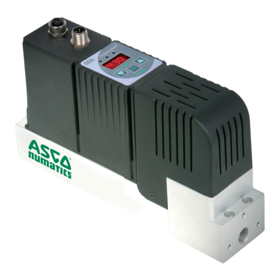
2-Port Flow Control Valve with Digital Electronics
2-Wege-Durchfl ussregelventil mit Digitaler Technik
Vanne de régulation de débit à 2 orifices
Series / Baureihe / Série 607
F
LOWTRONIC
Electronique numérique
D
Installation manual
Installation manual
Installationshandbuch
Installationshandbuch
Manuel d'installation
Manuel d'installation
IM14156.R4
GB
DE
FR
Publicité
Chapitres
Table des Matières

Manuels Connexes pour ASCO Numatics FlowtronicD 607 Série


Sommaire des Matières pour ASCO Numatics FlowtronicD 607 Série
- Page 1 LOWTRONIC 2-Port Flow Control Valve with Digital Electronics 2-Wege-Durchfl ussregelventil mit Digitaler Technik Vanne de régulation de débit à 2 orifices Electronique numérique Series / Baureihe / Série 607 Installation manual Installation manual Installationshandbuch Installationshandbuch Manuel d’installation Manuel d’installation IM14156.R4...
-
Page 2: Table Des Matières
The information in this manual is subject to change without notice. In no event shall ASCO NUMATICS be liable for technical or editorial errors or omissions. Neither is any liability assumed for accidental or consequential damages arising out of or in connection with the supply or use of the information contained herein. -
Page 3: Description
INSTALLATION DESCRIPTION The F flow controller is especially designed for applications placing extreme dynamic demands on flow LOwTRONIC control. It consists of a fast, direct-acting 2-port proportional valve and a control unit that contains all the electronics and sensors. The F offers precise flow adjustment and responds to outside influences within no time at all. -
Page 4: Manual Setpoint Adjustment
INSTALLATION MANUAL SETPOINT ADJUSTMENT (HAND) After an interruption in the power supply, press both arrow buttons located beneath the display during power up to switch to the manual mode. The operating mode is indicated by the letters “H n d” in the display. The "H n d"... -
Page 5: Electrical Connection
INSTALLATION ELECTRICAL CONNECTION 5-pin M12 female connector (view on soldered side) M12 connector Valve Control +24V supply voltage Supply voltage GND 250 Ohm at current setpoint Setpoint 0-10V (or 0-20 / 4-20mA) Setpoint GND (only for 6-wire cable) Analog output: Feedback Only at current output: 0-10V... -
Page 6: Pneumatic Connection
INSTALLATION PNEUMATIC CONNECTION The air flow is from port 1 in the direction of the arrow. Pressure supply Outlet Inch screw connections (pipe threads) must be used. Each screw connections must be lined with a fitting synthetic sealing disc. Do not use Teflon sealing tape or hemp as they may get inside the valve and damage it. The diameter of the pneumatic lines must be adjusted to the nominal diameter of the valve. -
Page 7: Technical Characteristics
INSTALLATION FIELD-PROGRAMMABLE SETTINGS (cont'd) AUTOTUNE AUTOTUNE determines the forward current the proportional valve needs to open. This control parameter, called forward offset, is permanently stored. AUTOTUNE can be activated in the three following ways: 1. Press and hold the AUTOTUNE button, switch the supply voltage off and on again, and release the AUTOTUNE but- ton. -
Page 8: Accessories
INSTALLATION ACCESSORIES Description CODES software "ASCO-FlowCom-Light" - CD-ROM 881 00 895 LOwTRONIC software "ASCO-FlowCom-Expert" - CD-ROM 881 00 896 LOwTRONIC G 1/2" adapter 881 60 701 881 60 702 G 3/8" adapter 881 00 897 USB cable for connection of F to PC LOwTRONIC 881 00 256... - Page 9 INSTALLATION Weight: 0,85 kg Orifice size 2 - 6 mm (5-1000 l/min) M12x1 connector M12x1 USB connection * (optional) * (optional) G1/2" adapter (88160701) G1/2" adapter (88160701) or G3/8" adapter (88160702) or G3/8" adapter (88160702) Mounting with M4 for earth screw 4xM4 screws from top or 4xM5 from bottom IM14156-9...
- Page 10 INSTALLATION ASCO Numatics GmbH Otto-Hahn-Straße 7-11 75248 Ölbronn-Dürrn Germany Tel: +49 7237 996-0 Email: asconumatics-de@emerson.com www.asconumatics.eu IM14156-10...
- Page 11 2-Wege-Durchfl ussregelventil mit Digitaler Technik Baureihe 607 LOWTRONIC Installationshandbuch IM14156-DE.R4...
- Page 12 DIE IN DIESEM HANDBUCH ENTHALTENEN ANGABEN KÖNNEN OHNE VORHERIGE ANKÜNDIGUNG GEÄNDERT WERDEN. ASCO NUMATICS übernimmt keinerlei Haftung für technische oder redaktionelle Fehler oder Ungenauigkeiten oder für versehentlich entstehende Schäden oder Folgeschäden, die durch die Bereitstellung dieses Handbuchs oder aus der Anwendung desselben entstehen.
-
Page 13: Beschreibung
INSTALLATION BESCHREIBUNG Der Durchflussregler F wurde speziell für Anwendungen entwickelt, die höchste dynamische Anforde- LOwTRONIC rungen an die Durchflussregelung stellen. Es besteht aus einem hochdynamischen, direktbetätigten 2-Wege-Pro- portionalventil und einer Regeleinheit, die die gesamte Regelelektronik und Sensorik beinhaltet. Das F LOwTRONIC regelt exakt den Durchfluss und reagiert auf Störgrößen von außen innerhalb kürzester Zeit. -
Page 14: Manuelle Sollwert-Verstellung
INSTALLATION MANUELLE SOLLWERT-VERSTELLUNG (HANDBETRIEB) Wird die Versorgungsspannung unterbrochen, wird nach einem erneuten Zuschalten der Versorgungsspannung und bei gleichzeitigen Drücken der beiden Pfeiltasten unterhalb des Displays in den Betriebszustand „Handbetrieb“ gewechselt. Dieser Betriebszustand wird im Display durch die Zeichen "H n d" angezeigt. Die Anzeige "H n d"... -
Page 15: Elektrischer Anschluss
INSTALLATION ELEKTRISCHER ANSCHLUSS =max. 200mA/4,8W 1. Das Ventil darf nur mit einer Versorgungsspannung von 24VDC +15%/-10% und einer maximalen Welligkeit von 10% betrieben werden. (Eine Einspeisung über Diodenbrücke ist nicht gestattet). Überspannungen und Welligkeiten au- ßerhalb dieser Toleranzen können zu einer Beschädigung der Elektronik führen. 2. -
Page 16: Pneumatischer Anschluss
INSTALLATION PNEUMATISCHER ANSCHLUSS Die pneumatische Durchflussrichtung ist von Anschluss 1 in Pfeilrichtung. Druckversorgung Ausgang Es sind zöllige Verschraubungen (Rohrgewinde) zu verwenden. Jede Verschraubung ist mit einem passenden Kunststoffdichtring zu unterlegen. Teflondichtband und Hanf dürfen nicht verwendet werden, da sie in das Innere des Ventils gelangen können. Der Querschnitt der Pneumatikleitungen ist der Nennweite des Ventils anzupassen. -
Page 17: Technische Daten
INSTALLATION EINSTELLMÖGLICHKEITEN (Fortsetzung) AUTOTUNE AUTOTUNE ermittelt den Ansteuerstrom, den das Proportionalventil benötigt, um zu öffnen. Dieser als Vorsteuernullpunkt bezeichnete Regelparameter wird permanent abgespeichert. Um AUTOTUNE zu starten, gibt es drei Möglichkeiten: 1. Die Taste AUTOTUNE gedrückt halten, die Versorgungsspannung aus- und wieder einschalten und die Taste anschlie- ßend loslassen. -
Page 18: Zubehör
INSTALLATION ZUBEHÖR Beschreibung Bestell-Code -Software "ASCO-FlowCom-Light" auf CD-ROM 881 00 895 LOwTRONIC -Software "ASCO-FlowCom-Expert" auf CD-ROM 881 00 896 LOwTRONIC G 1/2"-Adapter 881 60 701 G 3/8"-Adapter 881 60 702 USB-Verbindungskabel zwischen F und PC 881 00 897 LOwTRONIC Gerade M12 Leitungsdose, 5-polig, mit Schraubklemmen 881 00 256 M12 Winkel-Leitungsdose, 5-polig, mit Schraubklemmen 881 00 725... - Page 19 INSTALLATION Gewicht: 0,85 kg Nennweite 2 - 6 mm (5-1000 l/min) * (optional) * (optional) G1/2"-Adapter (88160701) G1/2"-Adapter (88160701) oder G3/8"-Adapter (88160702) oder G3/8"-Adapter (88160702) IM14156-19...
- Page 20 INSTALLATION ASCO Numatics GmbH Otto-Hahn-Straße 7-11 75248 Ölbronn-Dürrn Germany Tel: +49 7237 996-0 Email: asconumatics-de@emerson.com www.asconumatics.eu IM14156-20...
- Page 21 Vanne de régulation de débit à 2 orifi ces Electronique numérique ÉRIE LOWTRONIC Manuel d'installation IM14156-FR.R4...
- Page 22 NOTES Les informations contenues dans le présent manuel sont susceptibles d’être modifiées sans préavis. ASCO NUMATICS ne peut être tenu responsable des omissions techniques ou rédactionnelles, ni des dommages accidentels ou consécutifs à la fourniture ou l’utilisation du présent document.
-
Page 23: Description
INSTALLATION DESCRIPTION Le régulateur de débit F est parfaitement adapté pour les régulations de débit extrêmement dynamiques. Il est LOwTRONIC composé d’une vanne proportionnelle à 2 voies à commande directe pour un temps de réponse court, d'un bloc capteurs de pression et d'une électronique numérique de régulation. Le F régule et maintient le débit constant quelles LOwTRONIC que soient les perturbations externes. -
Page 24: Reglage Manuel De La Consigne (Mode Manuel)
INSTALLATION REGLAGE MANUEL DE LA CONSIGNE (MODE MANUEL) Pour passer en mode Manuel après une coupure de l’alimentation électrique, appuyer sur les deux boutons-pous- soirs à flèche qui se trouvent sous l’affichage pendant la remise sous tension. Le mode de fonctionnement est indiqué... -
Page 25: Raccordement Électrique
INSTALLATION RACCORDEMENT ELECTRIQUE Connecteur femelle M12 5 broches (vue du côté soudure) Connecteur M12 Vanne Contrôle Alimentation +24V Masse d’alimentation 250 Ohm à la consigne courante Consigne 0-10V (ou 0-20 / 4-20mA) Masse consigne (seulement pour câble à 6 fils) Sortie analogique: Retour Seulement pour... -
Page 26: Raccordement Pneumatique
INSTALLATION RACCORDEMENT PNEUMATIQUE Le sens de circulation de l'air est indiqué par la flèche. Alimentation Sortie Les 2 orifices sont disponibles avec un taraudage Gaz. Chaque connexion vissée doit être montée avec un joint d’étanchéité. Ne pas utiliser de ruban d’étanchéité en PTFE ou de chanvre car ils pourraient pénétrer à l’intérieur de la vanne et l’endommager. -
Page 27: Caractéristiques Techniques
INSTALLATION REGLAGES PROGRAMMABLES SUR SITE (suite) AUTOTUNE (FONCTION AUTO-REGLAGE) La fonction AUTOTUNE détermine le courant de commande requis pour activer l'ouverture de la vanne proportionnelle. Ce paramètre de contrôle, appelé « décalage avancé », est enregistré en permanence. La fonction AUTOTUNE peut être activée de trois manières différentes: 1. -
Page 28: Accessoires
INSTALLATION ACCESSOIRES Description CODES Logiciel «ASCO-FlowCom-Light» pour le F - CD-ROM 881 00 895 LOwTRONIC Logiciel «ASCO-FlowCom-Expert» pour le F - CD-ROM 881 00 896 LOwTRONIC Adaptateur G 1/2" 881 60 701 Adaptateur G 3/8" 881 60 702 881 00 897 Câble USB pour le raccordement du F au PC LOwTRONIC... - Page 29 INSTALLATION Masse: 0,85 kg Diamètre nominal 2 - 6 mm (5-1000 l/min) Connecteur M12x1 Connecteur M12x1 USB *(optionnel) *(optionnel) Adaptateur G1/2 (88160701) Adaptateur G1/2 (88160701) ou adaptateur (88160702) ou adaptateur (88160702) Montage avec 4 vis M4 par le dessus M4 pour vis de Terre Ou 4 vis M5 par le dessous IM14156-29...
- Page 30 YOUR NOTES / IHRE NOTIZEN / VOS NOTES IM14156-30...
- Page 31 YOUR NOTES / IHRE NOTIZEN / VOS NOTES IM14156-31...
- Page 32 INSTALLATION ASCO Numatics GmbH Otto-Hahn-Straße 7-11 75248 Ölbronn-Dürrn Germany Tel: +49 7237 996-0 Email: asconumatics-de@emerson.com www.asconumatics.eu IM14156-32...