Häfele dialock EPC Notice D'emploi Et De Montage

Cylindre électronique profil européen
Masquer les pouces Voir aussi pour dialock EPC:
Table des Matières

Publicité

Les langues disponibles
  • FR

Les langues disponibles

Liens rapides

Montage- und Bedienungsanleitung
Installation and Operating Instructions
Notice d'emploi et de montage
Istruzioni di montaggio e di servizio
Guía de montaje y manejo
Cylindre électronique profil européen EPC
Elektronischer Profilzylinder EPC
Electronic Profile Cylinder EPC
Cilindro profilato elettronico EPC
Cilindro electrónico perfilado EPC
DE
EN
FR
IT
ES

Publicité

Table des Matières
loading

Sommaire des Matières pour Häfele dialock EPC

  • Page 1 Montage- und Bedienungsanleitung Installation and Operating Instructions Notice d’emploi et de montage Istruzioni di montaggio e di servizio Guía de montaje y manejo Elektronischer Profilzylinder EPC Electronic Profile Cylinder EPC Cylindre électronique profil européen EPC Cilindro profilato elettronico EPC Cilindro electrónico perfilado EPC...
  • Page 2: Table Des Matières

    Montage- und Bedienungsanleitung Inhalt Allgemein ..........2 Sicherheitshinweise .
  • Page 3: Allgemein

    Montage- und Bedienungsanleitung Allgemein Achtung Dieses Symbol kennzeichnet Textstellen, die unbedingt zu beachten sind. Die Nichtbeachtung kann zu Personen- oder Sachschäden führen. Hinweis Dieses Symbol kennzeichnet Textstellen, die nützliche Informationen enthalten. Sicherheitshinweise Diese Montage- und Bedienungsanleitung unbedingt vor Montage und Inbetriebnahme des Elektronischen Profilzylinders EPC vollständig durchlesen.
  • Page 4: Lieferumfang

    Montage- und Bedienungsanleitung Lieferumfang Beschreibung Artikelnummer Elektronischer Profilzylinder EPC mit Zylinderadapter, Außen- und Innenknauf. Der Zylinderadapter und der Innen- knauf sind nicht im Lieferumfang des Elektronischen Profilzy- linders EPC enthalten. Elektronik Set EPC Integra 917.38.000 Elektronik Set EPC Standard 917.33.000 Batteriepack EPC (zwei 3 V Lithium-Batterien) 910.54.960 Nicht im Lieferumfang enthalten sind folgende Häfele Produkte...
  • Page 5 Montage- und Bedienungsanleitung Beschreibung Artikelnummer Programmier-Key-Card xxx.xx.xxx Lösch-Key-Card xxx.xx.xxx Notstromwerkzeug 917.93.391 Oben-Seite Unten-Seite Elektronischer Profilzylinder EPC - Stand 05.2008 - 732.29.490...
  • Page 6 Montage- und Bedienungsanleitung Innenknauf (1) Einsteckschloss (7) Stulpschraube (6) Zylinderadapter (2) Batterien (4) Lesemodul (3) Bohrung (8) (Außenknauf) Haube (5) Abb. 1 Elektronischer Profilzylinder EPC - Stand 05.2008 - 732.29.490...
  • Page 7: Kombinationsmöglichkeiten

    Montage- und Bedienungsanleitung Kombinationsmöglichkeiten Außen Innen Lesemodul geöffnet mit Batterie und Steuereinheit Knauf oder Lesemodul Lesemodulkappe Zylinderadapter Abb. 2 Leistungsmerkmale • Schnelle und einfache Montage. • Keine Bohrungen und Verkabelung erforderlich. • Passend für alle DIN-Schlösser. • Einfache Programmierung. • Batteriebetrieben (Batterielebensdauer ca.
  • Page 8: Funktionsweise

    Montage- und Bedienungsanleitung Funktionsweise Der Elektronische Profilzylinder EPC ist nach Montage und Inbetriebnahme nach der Zuweisung von Benutzerrechten sofort einsatzbereit. Im Betrieb des Elektronischen Profilzylinders EPC wird beim Vorhalten eines berech- tigten Benutzer-Key der Außenknauf für eine bestimmte Zeit an den Zylin- deradapter gekoppelt.
  • Page 9: Vorbereitung

    Montage- und Bedienungsanleitung Stulpschraube Türblatt Bohrung Oberkante der Innenrosette Wichtig bei der Bestellung sind die Maße A und B: Oberkante der Außenrosette A = Außenmaß [mm]: Abstand zwi- schen der Außenkante der Rosette und der Mitte der Stulpschraubenbohrung B = Innenmaß [mm]: Abstand zwischen der Innenkante der Rosette und der Mitte der Stulpschraubenbohrung Abb.
  • Page 10: Montage

    Montage- und Bedienungsanleitung Montage Die Installation des Elektronischen Profilzylinder EPC muss durch eine qualifizierte Fachkraft erfolgen. Bei Nichtbeachtung dieser Anleitung kann der Elektronische Profilzylinder EPC beschädigt werden. Die Tür nicht schließen, bevor die nachfolgenden Schritte der Montage und der Inbetriebnahme komplett ausgeführt worden sind. Andernfalls ist ein Öffnen der Tür von außen nicht mehr möglich.
  • Page 11: Außenknauf

    Montage- und Bedienungsanleitung Außenknauf Außenknauf noch nicht montieren! Bevor der Außenknauf montiert werden kann, muss die nachfolgend beschriebene Erstinbetriebnahme vollständig durchgeführt werden. Andernfalls ist bei einer möglichen Funktionsstörung des Elektronischen Profilzylinders EPC keine Demontage mehr möglich. Erst wenn Programm-Key-Card, Lösch-Key-Card und mindestens eine Benutzer-Key-Card bei der Erstinbetriebnahme korrekt zugewiesen worden sind, darf die Montage des Außenknaufs erfolgen.
  • Page 12: Schließrecht Einer Benutzer-Key-Card Zuweisen

    Montage- und Bedienungsanleitung Grüne Programmier-Key-Card Batterien einlegen, dabei auf richtige Polung achten (Abb.1). Grüne und rote LED blinken für einige Sekunden abwechselnd. Danach blinkt die grüne LED. Während die grüne LED blinkt, die grüne Programmier-Key-Card vor den Außenknauf halten, Abstand maximal 2 cm. Bei erfolgreichem Zuweisen leuchtet die grüne LED kurz auf und es ertönt ein akustisches Signal.
  • Page 13: Endmontage

    Montage- und Bedienungsanleitung Endmontage Die Endmontage ist erst nach erfolgreicher Erstinbetriebnahme durchzuführen. Außenknauf durch die Außenrosette stecken. Außenknauf von außen in den Zylinderadapter schieben bis er einrastet. Außenrosette festschrauben. Haube ausrichten (Abb. 4) und auf den Außenknauf bis zu den Arretier- stiften schieben.
  • Page 14: Schließrecht Einem Benutzer-Key Zuweisen

    Montage- und Bedienungsanleitung Schließrecht einem Benutzer-Key zuweisen Grüne Programmier-Key-Card vor den Außenknauf halten. Die rote LED leuchtet kurz auf und es ertönt ein akustisches Sig- nal. Danach blinkt die grüne LED. Anzulernenden Benutzer-Key innerhalb von 5 Sekunden vor den Außenknauf halten. Grüne LED leuchtet und es ertönt ein akustisches Signal.
  • Page 15: Schließrecht Allen Benutzer-Keys Entziehen

    Montage- und Bedienungsanleitung Schließrecht allen Benutzer-Keys entziehen Wenn ein Benutzer-Key verloren wurde und nicht mehr schließberechtigt sein soll, müssen für alle Benutzer-Keys das Schließrecht entzogen werden. Anschließend müssen allen schließberechtigten Benutzer-Keys wieder Schließrechte zugewiesen werden (siehe Schließrecht einem Benutzer-Key zuweisen). Führen Sie diesen Vorgang nicht aus, wenn Sie keinen Benutzer-Key zur Hand haben.
  • Page 16: Bedienung

    Montage- und Bedienungsanleitung Bedienung Öffnen Einen berechtigten Benutzer-Key vor den Außenknauf halten. Die LED leuchtet kurz rot auf, dann grün und es ertönt ein akustisches Signal. Wenn die LED nicht von rot auf grün umschaltet und das akustische Signal zweimal ertönt: Den Benutzerschlüssel näher vor den Außenknauf halten.
  • Page 17: Batteriewechsel

    Montage- und Bedienungsanleitung Batteriewechsel Blinkt die LED beim Öffnen abwechselnd grün und rot und ertönt dreimal ein kurzes akustisches Signal, dann haben die Batterien nicht mehr genügend Kapazität. Die Batterien müssen umgehend ausgewechselt werden. Batteriewechsel-Key-Card vor den Außenknauf halten (max. 1 cm Abstand).
  • Page 18: Demontage/Montage

    Montage- und Bedienungsanleitung Demontage/Montage Demontage-Key-Card vor den Außenknauf halten (max. 1 cm Abstand). Rote und grüne LED blinken abwechselnd und ein Signal ertönt. Grüne Programmierkarte vor den Außenknauf halten. Der Montagemodus ist aktiv. Der Außenknauf mindestens um 180 Grad drehen und leicht ziehen. Nach 3 Sekunden verriegelt der Außenknauf wieder.
  • Page 19: Notbestromung

    Montage- und Bedienungsanleitung Notbestromung Blinkt die LED beim Öffnen abwechselnd grün und rot, haben die Batterien nicht mehr genügend Kapazität. Die Batterien sind in diesem Fall sofort zu wechseln (siehe Batteriewechsel). Werden die Batterien nicht ersetzt, ist die Öffnungsfunktion nicht mehr gewährleistet.
  • Page 20 Montage- und Bedienungsanleitung Beim einfachen Reset wird der Projektcode des EPC zurückgesetzt. Für die spätere Inbetriebnahme wird jeder Spezialtransponder ohne Autorisierung akzeptiert. Ist eine Dialock MDU für die Durchführung des Reset notwendig, beachten Sie die Anweisungen in der Bedienungsanleitung der Dialock MDU.
  • Page 21: Servicevertrag

    Montage- und Bedienungsanleitung Servicevertrag Häfele bietet einen Servicevertrag (24 h/365 Tage) mit garantierter Reaktionszeit und kostenfreiem Telefonsupport an. Dialock Kunden ohne Servicevertrag wählen +49 (0) 180 / 50 50 50 1 (0,14 €/Minute aus dem deutschen Festnetz). Wartung Der Elektronische Profilzylinder EPC ist wartungsfrei. Elektronischer Profilzylinder EPC - Stand 05.2008 - 732.29.490...
  • Page 22: Anhang

    Montage- und Bedienungsanleitung Anhang Technische Daten Maßzeichnung Abb. 8 Maße Außenknauf Länge 41,0 mm Außenknauf Durchmesser Ø 40,0 mm Maße Innenknauf Länge 20,0 mm Innenknauf Durchmesser Ø 29,5 oder 34 mm Batterietyp 2 Stück Typ CR2 ca. 2 Jahre Batterielebensdauer (bei durchschnittlicher Benutzung) Relative Luftfeuchtigkeit 0 -95% (nicht kondensierend)
  • Page 23: Normen

    Montage- und Bedienungsanleitung Normen DIN EN 179 Die Auswahl erfolgt gemäß EG-Konformitätszertifikat 0432-BPR-0041 in Anlehnung an die DIN EN 179. Die Schlösser mit dem Kennzeichen "b)" können eingesetzt werden. b) "Schließzylinder haben keinen Einfluss auf die einwandfreie Fluchtfunktion." Allgemein: Panikschlösser, die keine definierte Schließnasenstellung benö- tigen, können mit dem Elektronischer Profilzylinder EPC eingesetzt werden.
  • Page 24 Montage- und Bedienungsanleitung Elektronischer Profilzylinder EPC - Stand 05.2008 - 732.29.490...
  • Page 25 Installation and Operating Instructions Contents General information ........25 Safety Instructions .
  • Page 26: General Information

    Installation and Operating Instructions General information Attention This symbol marks paragraphs you should pay particular attention to. Failure to observe this warning may lead to damage to person or property. Note This symbol marks paragraphs containing useful information. Safety Instructions These installation and operating instructions must be read carefully before installing and starting-up the EPC electronic profile cylinder.
  • Page 27: Scope Of Delivery

    Installation and Operating Instructions Scope of delivery Catalogue Description number EPC electronic profile cylinder with cylinder adapter, external and internal knobs. The cylinder adapter and the internal knob are not supplied with the EPC electronic profile cylinder. EPC Integra electronics set 917.38.000 Elektronik Set EPC Standard 917.33.000...
  • Page 28 Installation and Operating Instructions Catalogue Description number Programming key card xxx.xx.xxx Clearing key card xxx.xx.xxx Emergency power supply unit 917.93.391 Bottom EPC Electronic Profile Cylinder - Status 05.2008 - 732.29.490...
  • Page 29 Installation and Operating Instructions Internal knob (1) Mortise lock (7) Cylinder adapter (2) Forend screw (6) Batteries (4) Reader module (3) Drill hole (8) (External knob) Cover (5) Fig. 1 EPC Electronic Profile Cylinder - Status 05.2008 - 732.29.490...
  • Page 30: Possible Combinations

    Installation and Operating Instructions Possible combinations Outside Inside Reader module open with battery and control unit Knob reader module Reader module cover Cylinder adapter Fig. 2 Features • Quick and easy installation. • No drilling and no cables required. • Suitable for all DIN locks.
  • Page 31: Operating Principle

    Installation and Operating Instructions Operating principle After installation, commissioning and allocating user authorisations, the EPC electronic profile cylinder is immediately ready for use. If an authorised user key is presented to the EPC electronic profile cylinder, the external knob is linked to the cylinder adapter for a certain period of time. This way the door lock can be operated by turning the external knob.
  • Page 32: Preparation

    Installation and Operating Instructions Drill hole for forend Door leaf screw Upper edge of inside escutcheon Dimensions A and B are important for ordering: Upper edge of outside escutcheon A = External dimension [mm]: Distance between the outer edge of the escutcheon and the centre of the fo- rend screw drill hole B = Internal dimension [mm]:...
  • Page 33: Installation

    Installation and Operating Instructions Installation The installation of the EPC electronic profile cylinder must be car- ried out by trained qualified personnel. Failing to adhere to these installation and operating instructions may lead to damages to the EPC electronic profile cylinder. Do not close the door before the following installation and commis- sioning procedures are completed! Otherwise opening the door from outside will no longer be possible.
  • Page 34: External Knob

    Installation and Operating Instructions External knob Do not yet install the external knob! Before installing the external knob, the initial start-up procedure described in the following must be completed. Otherwise the EPC electronic profile cylinder cannot be removed again in case of mal- function.
  • Page 35: Green Programming Key Card

    Installation and Operating Instructions Green programming key card Insert batteries. Make sure the polarity is correct (Fig. 1). The green and red LEDs flash alternately for several seconds. Afterwards the green LED flashes. While the green LED flashes, present the green programming key card to the external knob at a maximum distance of 2 cm.
  • Page 36: Final Assembly

    Installation and Operating Instructions Final assembly Make sure that the initial start-up has been completed successfully before carrying out the final assembly. Push the external knob through the inside escutcheon. Insert the external knob into the cylinder adapter from the outside until it locks into place.
  • Page 37: Allocating Locking Authorisation To A User Key

    Installation and Operating Instructions Allocating locking authorisation to a user key Present the green programming key card to the external knob. The red LED flashes briefly and an acoustic signal is audible. Afterwards the green LED flashes. Present the user key that has to be trained to the external knob within 5 seconds.
  • Page 38: Withdrawing Locking Authorisations From All User Keys

    Installation and Operating Instructions Withdrawing locking authorisations from all user keys If a user key is lost and shall not be authorised any longer, the locking author- isations has to be withdrawn from all user keys. Afterwards all locking authorisations must be re-allocated to the respective user keys (see Allocating locking authorisation to a user key).
  • Page 39: Operation

    Installation and Operating Instructions Operation Opening Present an authorised user key to the external knob. First the LED flashes red briefly, then flashes green and an acoustic signal is audible. In case the LED does not switch from red to green and the acoustic sig- nal is audible twice: Present the user key closer to the external knob.
  • Page 40: Battery Replacement

    Installation and Operating Instructions Battery replacement If during the unocking action the LED flashes alternately green and red and a short acoustic signal is audible three times, the batteries are low and have to be replaced immediately. Present the battery key card to the external knob (max. distance 1 cm). The green and red LEDs flash alternately and an acoustic signal is audible.
  • Page 41: Disassembly/Installation

    Installation and Operating Instructions Disassembly/installation Present the disassembly key card to the external knob (max. distance 1 cm). The green and red LEDs flash alternately and an acoustic signal is audible. Present the green programming key card to the external knob. The installation mode is activated.
  • Page 42: Emergency Power Supply

    Installation and Operating Instructions Emergency power supply: If the LED flashes alternately green and red during the unlocking action, the bat- teries are low and have to be replaced immediately (see Battery replacement). The unlocking function cannot be guaranteed if the batteries are not replaced.
  • Page 43 Installation and Operating Instructions The simple reset also resets the project code of the EPC. For the subsequent start-up every special transponder without authorisation will be accepted. In case the Dialock MDU is required for the reset, follow the operating instructions there of. Procedures Present the Dialock MDU “beam card”...
  • Page 44: Service Agreement

    Installation and Operating Instructions Service agreement Häfele offers a service agreement (24 hours / 365 days) with guaranteed response time and free telephone support. Dialock customers without service agreement are requested to contact +49 (0) 180 / 50 50 50 1 (0.14 €/minute for landline calls within Germany). Maintenance The EPC electronic profile cylinder is maintenance-free.
  • Page 45: Appendix

    Installation and Operating Instructions Appendix Technical data Dimensioned drawing Fig. 8 External knob length 41,0 mm External knob diameter Ø 40,0 mm Internal knob length 20,0 mm Internal knob diameter Ø 29,5 or 34 mm Battery type 2 pieces, Type CR2 Service life of battery Approx.
  • Page 46: Standards

    Installation and Operating Instructions Standards DIN EN 179 Selection is made in accordance with the EC certificate of conformity 0432- BPR-0041 based on DIN EN 179. Locks marked "b)" may be used. b) "Locking cylinders do not influence the flawless escape function." General information: Panic locks that do not require a defined locking lug position can be used in combination with the EPC electronic profile cylinder.
  • Page 47 Installation and Operating Instructions EPC Electronic Profile Cylinder - Status 05.2008 - 732.29.490...
  • Page 48 Notice d’emploi et de montage Sommaire Généralités ..........48 Consignes de sécurité...
  • Page 49: Généralités

    Notice d’emploi et de montage Généralités Attention Ce symbole signale des passages du texte qui doivent absolument être respectés. Le non-respect de ces prescriptions peut entraîner des dommages pour les personnes ou les biens. Remarque Ce symbole signale des passages de texte comportant des informations utiles.
  • Page 50: Contenu De La Livraison

    Notice d’emploi et de montage Contenu de la livraison Description Référence Cylindre électronique profil européen EPC avec adaptateur pour cylindre, boutons extérieur et intérieur. L’adaptateur pour cylindre et le bouton intérieur ne sont pas compris dans le contenu de la livraison du cylindre électronique profil euro- péen EPC.
  • Page 51 Notice d’emploi et de montage Description Référence Key card de programmation xxx.xx.xxx Key card d'effacement xxx.xx.xxx Outil d'alimentation de secours 917.93.391 En haut En bas Cylindre électronique profil européen EPC - État au 05.2008 - 732.29.490...
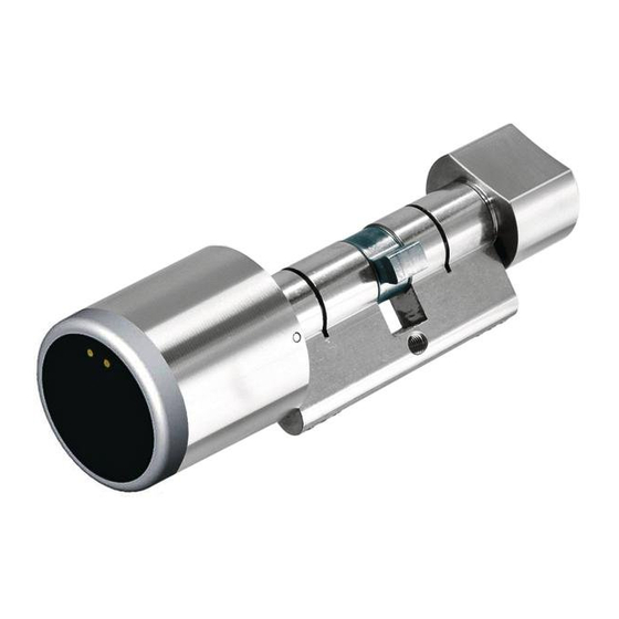
  • Page 52 Notice d’emploi et de montage Bouton intérieur (1) Serrure à encastrer (7) Adaptateur pour cylindre (2) Vis têtière (6) Piles (4) Module de lecture (3) Perçage (8) (Bouton extérieur) Capuchon (5) Fig. 1 Cylindre électronique profil européen EPC - État au 05.2008 - 732.29.490...
  • Page 53: Possibilités De Combinaisons

    Notice d’emploi et de montage Possibilités de combinaisons Extérieur Intérieur Module de lecture ouvert avec pile et unité de commande Bouton ou module de lecture Capuchon de module de lecture Adaptateur pour cylindre Fig. 2 Caractéristiques • Montage simple et rapide. •...
  • Page 54: Mode De Fonctionnement

    Notice d’emploi et de montage Mode de fonctionnement Après le montage et la mise en service, le cylindre électronique profil euro- péen EPC est prêt à être utilisé dès que des droits d’utilisateurs ont été attri- bués. Lorsque le cylindre électronique profil européen EPC est en fonctionnement, le bouton extérieur et l’adaptateur pour cylindre sont cou- plés pendant une certaine durée lors de la présentation d’une clé...
  • Page 55: Préparation

    Notice d’emploi et de montage Perçage de la Battant de la porte vis têtière Arrête supérieure de la rosace intérieure Les dimensions A et B sont impor- tantes lors de la commande : Arrête supérieure de la rosace extérieure A = Dimension extérieure [mm] : Dis- tance entre le chant extérieur de la ro- sace et le milieu du perçage de la vis têtière...
  • Page 56: Montage

    Notice d’emploi et de montage Montage Le montage du cylindre électronique profil européen EPC ne doit être exécuté que par du personnel qualifié et formé à cet effet. Le non-respect des instructions de la présente notice peut endommager le cylindre électronique profil européen EPC. Ne pas fermer la porte avant d’avoir exécuté...
  • Page 57: Bouton Extérieur

    Notice d’emploi et de montage Bouton extérieur Ne pas encore installer le bouton extérieur ! Avant de pouvoir monter le bouton extérieur, la mise en service décrite ci-après doit avoir été entièrement effectuée. Dans le cas contraire, aucun démontage ne serait plus possible lors d’une éventuelle panne du cylindre électronique profil européen EPC.
  • Page 58: Affecter Un Droit De Fermeture À Une Key Card Utilisateur

    Notice d’emploi et de montage Key card de programmation verte Mettre les piles en place en veillant à respecter la polarité (Fig.1). Les DEL verte et rouge clignotent en alternance pendant quelques secondes. Ensuite, seule la DEL verte clignote. Pendant que la DEL verte clignote, tenir la key card de programmation verte devant le bouton extérieur, distance maximale 2 cm.
  • Page 59: Montage Final

    Notice d’emploi et de montage Montage final Le montage final ne peut être réalisé que lorsque la première mise en service a été effectuée avec succès. Passer le bouton extérieur par la rosace extérieure. Enfoncer le bouton extérieur dans l’adaptateur pour cylindre jusqu’à enclenchement.
  • Page 60: Affecter Un Droit De Fermeture À Une Clé Utilisateur

    Notice d’emploi et de montage Affecter un droit de fermeture à une clé utilisateur Tenir la key card de programmation verte devant le bouton extérieur. La DEL rouge s’allume brièvement et un signal retentit. Ensuite, seule la DEL verte clignote. Pour procéder à...
  • Page 61: Retirer Les Droits De Fermeture À Toutes Les Clés Utilisateurs

    Notice d’emploi et de montage Retirer les droits de fermeture à toutes les clés utilisateurs Si une clé utilisateur a été perdue et qu’elle ne doit plus posséder de droit de fermeture, le droit de fermeture doit être retiré à toutes les clés utilisateurs. Ensuite, les droits de fermeture doivent être réaffectés à...
  • Page 62: Utilisation

    Notice d’emploi et de montage Utilisation Ouverture Tenir la clé utilisateur autorisée devant le bouton extérieur. La DEL rouge s’allume brièvement suivi du couleur vert et un signal retentit. Si la DEL ne passe pas du rouge au vert et que le signal retentit deux fois : Tenir la clé...
  • Page 63: Échange Des Piles

    Notice d’emploi et de montage Échange des piles Si lors de l’ouverture la DEL clignote alternativement vert et rouge et qu’un bref signal retentit trois fois alors la capacité des piles est insuffisante. Les piles doivent être immédiatement changées. Tenir la key card échange des piles verte devant le bouton extérieur (distance maximale 1 cm).
  • Page 64: Démontage/Montage

    Notice d’emploi et de montage Démontage/Montage Tenir la key card de démontage devant le bouton extérieur (distance maximale 1 cm). Les DEL verte et rouge clignotent alternativement et un signal retentit. Tenir la key card de programmation verte devant le bouton extérieur. Le mode de montage est activé.
  • Page 65: Alimentation Électrique Auxiliaire

    Notice d’emploi et de montage Alimentation électrique auxiliaire Si lors de l’ouverture la DEL clignote alternativement vert et rouge, la capa- cité des piles est insuffisante. Dans ce cas, procéder immédiatement à l’échange des piles (voir Changement des piles). Si les piles ne sont pas échangées, la fonction d’ouverture n’est plus garan- tie.
  • Page 66 Notice d’emploi et de montage Lors de la réinitialisation simple, le code projet de l’EPC est remis à zéro. Pour une mise en service ultérieure, chaque transpondeur spécial sera accepté sans autorisation. Si un Dialock MDU est nécessaire pour l’exécution de la réinitialisation, respecter les prescriptions du mode d’emploi du Dialock MDU.
  • Page 67: Contrat De Maintenance

    Notice d’emploi et de montage Contrat de maintenance Häfele propose un contrat de maintenance (24 h sur 24, 365 jours par an) avec temps de réaction garanti et assistance téléphonique. Les clients Dialock sans contrat de maintenance téléphonent au +49 (0) 180 / 50 50 50 1 (0,14 € à partir du réseau fixe allemand). Maintenance Le cylindre électronique profil européen EPC ne nécessite aucun entretien.
  • Page 68: Annexe

    Notice d’emploi et de montage Annexe Caractéristiques techniques Plan coté Fig. 8 Dimensions longueur bouton extérieur 41,0 mm Diamètre bouton extérieur Ø 40,0 mm Dimensions longueur bouton intérieur 20,0 mm Diamètre bouton intérieur Ø 29,5 ou 34 mm Type de pile 2 piles type CR2 Durée de vie des piles 2 ans (pour une utilisation moyenne)
  • Page 69: Normes

    Notice d’emploi et de montage Normes DIN EN 179 Le choix d’effectue conformément au Certificat de conformité CE 0432- BPR-0041 selon la norme DIN EN 179. Les serrures identifiées par "b)" peuvent être utilisées. b) "Les cylindres de fermeture nont aucune influence sur le parfait fonctionnement la fonction de fuite".
  • Page 70 Notice d’emploi et de montage Cylindre électronique profil européen EPC - État au 05.2008 - 732.29.490...
  • Page 71: Cenni Generali

    Istruzioni di montaggio e di servizio Indice Cenni generali ......... . 71 Avvertenze sulla sicurezza .
  • Page 72: Avvertenze Sulla Sicurezza

    Istruzioni di montaggio e di servizio Cenni generali Attenzione Questo simbolo indica le parti del testo a cui si deve prestare parti- colare attenzione. La mancata osservanza può provocare danni alle persone o alle cose. Avvertenza Questo simbolo indica parti del testo a cui si deve prestare partico- lare attenzione.
  • Page 73 Istruzioni di montaggio e di servizio Fornitura Descrizione Codice articolo Descrizione codice articolo Cilindro profilato elettronico EPC con adattatore cilindro, pomello esterno ed interno. L’adatta- tore cilindro e il pomello interno non sono compresi della for- nitura del cilindro profilato elettronico EPC. Set elettronico EPC Integra 917.38.000 Set elettronico EPC Standard...
  • Page 74 Istruzioni di montaggio e di servizio Descrizione Codice articolo Scheda di programmazione xxx.xx.xxx Scheda di cancellazione xxx.xx.xxx Attrezzatura per corrente di emergenza 917.93.391 Parte superiore Parte inferiore Cilindro profilato elettronico EPC - edizione 05.2008 - 732.29.490...
  • Page 75: Possibilità Di Combinazione

    Istruzioni di montaggio e di servizio Pomello interno (1) Serratura da infilare (7) Adattatore cilindro (2) Vite per piastra (6) Batterie (4) Modulo lettore (3) Foratura (8) (Pomello esterno) Cappuccio (5) Fig. 1 Cilindro profilato elettronico EPC - edizione 05.2008 - 732.29.490...
  • Page 76: Caratteristiche Tecniche

    Istruzioni di montaggio e di servizio Possibilità di combinazione Esterno Interno Modulo lettore aperto con batteria e centra- lina di comando Pomello o modulo di lettura Calotta modulo di lettura Adattatore cilindro Fig. 2 Caratteristiche tecniche • Montaggio rapido e semplice. •...
  • Page 77: Istruzioni Di Montaggio

    Istruzioni di montaggio e di servizio Modo di funzionamento Dopo il montaggio e la messa in funzione e dopo l’assegnazione dei diritti di utilizzo, il cilindro profilato elettronico EPC è subito pronto per l’uso. Quando il cilindro profilato elettronico EPC è in funzione, posizionando una chiave elettronica per utente autorizzata il pomello esterno viene accoppiato per un certo tempo all’adattatore cilindro.
  • Page 78: Preparazione

    Istruzioni di montaggio e di servizio Vite per piastra Pannello porta Foratura Angolo superiore del- la rosetta interna Importanti in fase di ordinazione sono le misure A e B: Angolo superiore del- la rosetta esterna A = Dimensione esterna [mm]: distanza tra il bordo esterno della rosetta e il centro del foro della vite per piastra B = Dimensione interna [mm]: distanza...
  • Page 79: Montaggio

    Istruzioni di montaggio e di servizio Montaggio L’installazione del cilindro elettronico EPC deve essere eseguita da personale specializzato e addestrato. La mancata osservanza di queste istruzioni può provocare danni al cilindro elettronico EPC. Si deve evitare di chiudere la porta prima di avere completato le seguenti fasi di montaggio e di messa in funzione.
  • Page 80: Pomello Esterno

    Istruzioni di montaggio e di servizio Pomello esterno Attendere prima di montare il pomello esterno! Prima di poter montare il pomello esterno è necessario portare completamente a termine una messa in funzione iniziale, come descritto qui di seguito. In caso contrario, se si verifica un difetto di funzionamento del cilindro profilato elettronico EPC, non sarà...
  • Page 81: Assegnazione Dell'autorizzazione Alla Chiusura Ad Una Scheda Per Utente

    Istruzioni di montaggio e di servizio Scheda di programmazione verde Inserire le batterie prestando attenzione a collegare la corretta polariz- zazione (Fig. 1). I LED verde e rosso lampeggiano in modo alternato per qualche secondo. Successivamente lampeggia il LED verde. Mentre il LED verde lampeggia, posizionare la scheda di programmazione verde davanti al pomello esterno, ad una distanza massima di 2 cm.
  • Page 82: Montaggio Finale

    Istruzioni di montaggio e di servizio Montaggio finale Il montaggio finale solo una volta portata a buon fine la messa in funzione iniziale. Inserire il pomello esterno attraverso la rosetta esterna. Spingere il pomello esterno dall’esterno nell’adattatore cilindro fino ad innestarlo in posizione.
  • Page 83: Assegnazione Dell'autorizzazione Alla Chiusura Ad Una Chiave Elettronica Per Utente

    Istruzioni di montaggio e di servizio Assegnazione dell’autorizzazione alla chiusura ad una chiave elettronica per utente Posizionare la scheda di programmazione verde davanti al pomello esterno. Il LED rosso lampeggia brevemente e si attiva un segnale acustico. Successivamente il LED verde lampeggia. Entro 5 secondi posizionare la chiave elettronica utente da program- mare davanti al pomello esterno.
  • Page 84: Revoca Dell'autorizzazione Alla Chiusura A Tutte Le Chiavi Elettroniche Per Utente

    Istruzioni di montaggio e di servizio Revoca dell’autorizzazione alla chiusura a tutte le chiavi elettroniche per utente Se una chiave elettronica per utente viene smarrita e non deve essere più autorizzata alla chiusura, si deve revocare il diritto alla chiusura a tutte le chiavi elettroniche per utente.
  • Page 85: Impiego

    Istruzioni di montaggio e di servizio Impiego Apertura Posizionare una chiave elettronica per utente autorizzata davanti al pomello esterno. Il LED lampeggia brevemente con luce rossa e si attiva un segnale acustico. Se il LED non commuta da rosso a verde e il segnale acustico si attiva due volte.
  • Page 86: Cambio Della Batteria

    Istruzioni di montaggio e di servizio Cambio della batteria Se con l’apertura il LED lampeggia alternativamente con luce verde e rossa e risuona brevemente per tre volte un segnale acustico, le batterie non hanno capacità sufficiente. Le batterie devono essere sostituite al più presto. Posizionare davanti al pomello esterno la scheda del cambio di batteria (massimo 1 cm di distanza).
  • Page 87: Smontaggio/Montaggio

    Istruzioni di montaggio e di servizio Smontaggio/montaggio Tenere la scheda di smontaggio davanti al pomello esterno (distanza massima 1 cm). I LED verde e rosso lampeggiano alternativamente e si attiva un segnale acustico. Posizionare la scheda verde di programmazione davanti al pomello esterno.
  • Page 88: Immissione Di Corrente Di Emergenza

    Istruzioni di montaggio e di servizio Immissione di corrente di emergenza: Se all’apertura il LED lampeggia con luce alternata verde e rossa, le batterie non hanno più capacità sufficiente. In questo caso è necessario sostituire al più presto le batterie (vedere sostituzione batterie). Se le batterie non vengono sostituite, la funzione di apertura non è...
  • Page 89 Istruzioni di montaggio e di servizio Con il reset semplice viene ripristinato il codice di progetto di EPC. Per la messa in funzione successiva è ammesso qualsiasi tran- sponder speciale senza autorizzazione. Se per eseguire il reset è necessaria una MDU Dialock, si devono seguire le indicazioni della guida di servizio della Dialock MDU.
  • Page 90: Contratto Di Assistenza

    Istruzioni di montaggio e di servizio Contratto di assistenza Häfele offre un contratto di assistenza (24 h/365 giorni) con tempi di rea- zione garantiti e supporto telefonico gratuito. I Clienti Dialock senza contratto di assistenza sono pregati di telefonare al numero +49 (0) 180 / 50 50 50 1 (€...
  • Page 91: Appendice

    Istruzioni di montaggio e di servizio Appendice Dati tecnici Disegno quotato Fig. 8 Dimensioni Pomello esterno Lunghezza 41,0 mm Pomello esterno Diametro Ø 40,0 mm Dimensioni Pomello esterno Lunghezza 20,0 mm Pomello interno Diametro Ø 29,5 oppure 34 mm Tipo di batteria 2 unità...
  • Page 92: Norme

    Istruzioni di montaggio e di servizio Norme DIN EN 179 La selezione è operata secondo il Certificato di Conformità CE 0432-BPR- 0041 in base alla normativa DIN EN 179. Si possono impiegare serrature con il contrassegno "b)". b) "Cilindri di chiusura non influenzano una funzione antipanico otti- male.”...
  • Page 93 Istruzioni di montaggio e di servizio Cilindro profilato elettronico EPC - edizione 05.2008 - 732.29.490...
  • Page 94 Guía de montaje y manejo Índice Advertencias generales ........95 Advertencias sobre seguridad .
  • Page 95: Advertencias Generales

    Guía de montaje y manejo Advertencias generales Atención Este símbolo señala las secciones del texto que es imprescindible tener en cuenta. No tenerlas en cuenta puede ser causa de lesiones personales o daños materiales. Nota Este símbolo señala las secciones del texto que contienen información de utilidad.
  • Page 96: Componentes Suministrados

    Guía de montaje y manejo Componentes suministrados Descripción N° de ref. Cilindro electrónico perfilado EPC con adaptador para cilin- dro, pomo exterior e interior. El adaptador para cilindro y el pomo interior no están incluidos en el suministro del cilindro electrónico perfilado EPC.
  • Page 97 Guía de montaje y manejo Descripción N° de ref. Llave-tarjeta de programación xxx.xx.xxx Llave-tarjeta de cancelación xxx.xx.xxx Herramienta para alimentación de emergencia 917.93.391 Lado superior Lado inferior Cilindro electrónico perfilado EPC - Estado del 05.2008 - 732.29.490...
  • Page 98 Guía de montaje y manejo Pomo interior (1) Cerradura para embutir (7) Adaptador para cilindro (2) Tornillo para el frente (6) Baterías (4) Módulo de lectura (3) Taladro (8) (Pomo exterior) Cubierta (5) Fig. 1 Cilindro electrónico perfilado EPC - Estado del 05.2008 - 732.29.490...
  • Page 99: Posibilidades De Combinación

    Guía de montaje y manejo Posibilidades de combinación Exterior Interior Módulo de lectura abierto con batería y unidad de control Pomo o módulo de lectura Tapa de módulo Adaptador de lectura para cilindro Fig. 2 Características • Montaje rápido y sencillo •...
  • Page 100: Funcionamiento

    Guía de montaje y manejo Funcionamiento Una vez montado y puesto en funcionamiento, el cilindro electrónico perfi- lado EPC se puede empezar a utilizar inmediatamente después de asignar los derechos de usuario. Cuando se sitúa una llave de usuario autorizado delante del cilindro electrónico EPC, el pomo exterior se acopla al adapta- dor para cilindro durante cierto tiempo, de manera que al girar el pomo exte- rior se acciona la cerradura de la puerta.
  • Page 101: Preparación

    Guía de montaje y manejo Tornillo del frente Puerta Taladro Borde superior de la roseta interior Para el pedido es importante deter- minar las medidas A y B: Borde superior de la roseta exterior A = Distancia exterior [mm]: Distancia entre el borde de la roseta exterior y el centro del taladro para el tornillo del frente.
  • Page 102: Montaje

    Guía de montaje y manejo Montaje La instalación del cilindro electrónico perfilado EPC únicamente debe confiarse a profesionales especializados. Si no se tiene en cuenta esta advertencia se puede dañar el cilindro EPC. No cierre la puerta antes de completar los siguientes pasos de montaje y el proceso de puesta en funcionamiento.
  • Page 103: Pomo Exterior

    Guía de montaje y manejo Pomo exterior ¡No monte todavía el pomo exterior! Antes de montar el pomo exterior es imprescindible completar el proceso de la primera puesta en funcionamiento según se describe a continuación. De lo contrario, si se produce algún fallo en el funcionamiento del cilindro electrónico perfilado EPC ya no se podrá...
  • Page 104: Asignar Derecho De Cierre A Una Llave-Tarjeta De Usuario

    Guía de montaje y manejo Llave-tarjeta de programación verde Coloque las baterías asegurándose de que la polaridad es correcta (Fig.1). Los indicadores LED verde y rojo parpadean varios segundos alternativamente. Después parpadea el LED verde. 2. Mientras parpadea el LED verde, mantenga la llave-tarjeta de pro- gramación verde delante del pomo exterior, a una distancia máxima de 2 cm.
  • Page 105: Montaje Final

    Guía de montaje y manejo Montaje final El montaje final sólo se debe realizar cuando la primera puesta en funcionamiento haya sido correcta. Introduzca el pomo exterior a través de la roseta exterior. Introduzca el pomo exterior desde fuera en el adaptador para cilindro hasta que encaje.
  • Page 106: Asignar Derecho De Cierre A Una Llave De Usuario

    Guía de montaje y manejo Asignar derecho de cierre a una llave de usuario Sitúe la llave-tarjeta de programación verde delante del pomo exterior. El LED rojo se ilumina brevemente y suena un tono de aviso. Después parpadea el LED verde. En menos de 5 segundos, sitúe delante del pomo exterior la llave de usuario que desea configurar.
  • Page 107: Cancelar El Derecho De Cierre De Todas Las Llaves De Usuario

    Guía de montaje y manejo Cancelar el derecho de cierre de todas las llaves de usuario Cuando se pierda una llave de usuario, y haya que cancelar los derechos de cierre, es preciso cancelar los derechos de cierre de todas las llaves de usuario.
  • Page 108: Manejo

    Guía de montaje y manejo Manejo Apertura Mantenga delante del pomo exterior una llave de usuario autorizada. El LED rojo se ilumina brevemente, seguido del color verde y suena un tono de aviso. Si el indicador LED no cambia de rojo a verde, y el tono de aviso suena dos veces: Sitúe la llave de usuario más cerca el pomo exterior.
  • Page 109: Sustitución De Las Baterías

    Guía de montaje y manejo Sustitución de las baterías Cuando los LED verde y rojo parpadean alternativamente al abrir la puerta y suena tres veces un tono de aviso corto, es señal de agotamiento de las baterías, que se deben sustituir lo más pronto posible. Sitúe la llave-tarjeta de sustitución de baterías delante del pomo exte- rior (a una distancia máxima de 1 cm).
  • Page 110: Desmontaje / Montaje

    Guía de montaje y manejo Desmontaje / Montaje Sitúe la llave-tarjeta de desmontaje delante del pomo exterior (a una distancia máxima de 1 cm). Los LED rojo y verde parpadean alternativamente y suena un tono de aviso. Sitúe la tarjeta de programación verde delante del pomo exterior. El modo de montaje está...
  • Page 111: Alimentación De Emergencia

    Guía de montaje y manejo Alimentación de emergencia Cuando los LED rojo y verde parpadean alternativamente al abrir la puerta, es señal de que las baterías están casi agotadas. En este caso, cambie inmediatamente las baterías (vea Cambiar las baterías) Si no se sustituyen las baterías, la función de apertura puede fallar en cual- quier momento.
  • Page 112 Guía de montaje y manejo Con un reinicio sencillo se repone el código de proyecto del cilindro EPC. Para su puesta en funcionamiento posterior se admite cualquier transpondedor especial sin autorización. Si hace falta una unidad Dialock MDU para reiniciar el cilindro, tenga en cuenta las instrucciones de la Guía de mantenimiento de la unidad Dialock MDU.
  • Page 113: Contrato De Asistencia Técnica

    Guía de montaje y manejo Contrato de asistencia técnica Häfele ofrece un contrato de asistencia técnica (24 h/365 días) con tiempo de reacción garantizado y soporte telefónico gratuito. Para clientes de Dialock sin contrato de asistencia técnica el teléfono es +49 (0) 180 / 50 50 50 1(0,14 €/ minuto desde la red de telefonía fija alemana) Mantenimiento El cilindro electrónico perfilado EPC no necesita mantenimiento.
  • Page 114: Anexo

    Guía de montaje y manejo Anexo Datos técnicos Dibujo acotado Fig. 8 Longitud pomo exterior 41,0 mm Diámetro pomo exterior Ø 40,0 mm Longitud pomo interior 20,0 mm Diámetro pomo interior Ø 29,5 ó 34 mm Batería 2 baterías tipo CR2 Vida útil de la batería aprox.
  • Page 115: Normas

    Guía de montaje y manejo Normas DIN EN 179 La selección se realizará según el certificado de conformidad EG 0432- BPR-0041 en relación con la norma DIN EN 179. Se pueden utilizar las cerraduras identificadas como "b)". b) "Cilindros de cierre que no afectan a la función de salida de emer- gencia."...
  • Page 116 Guía de montaje y manejo Cilindro electrónico perfilado EPC - Estado del 05.2008 - 732.29.490...
  • Page 118 Copyright Der Nachdruck dieses Dokuments, auch auszugsweise, oder die Nachahmung der Abbildungen und Zeichnungen sowie die Nachahmung der Gestaltung sind verboten. Für Druckfehler und Irrtümer, die bei der Erstellung der Montageanleitung unterlaufen sind, ist jede Haftung ausgeschlossen. Liefermöglichkeiten und technische Änderungen vorbehalten. Stand 05.2008 The reprint of this document, even extracts, or copying of the illustrations and drawings as well as copying of the layout are prohibited.

Table des Matières