VOLTCRAFT VC-590OLED Notice D'emploi
Masquer les pouces Voir aussi pour VC-590OLED:
Table des Matières

Publicité

Les langues disponibles

Les langues disponibles

Liens rapides

Bedienungsanleitung
Digitales Zangen-Multimeter
VC-590OLED
Best.-Nr. 1181861
Seite 2 - 39
Operating Instructions
Digital Clamp Multimeter
VC-590OLED
Item No. 1181861
Page 40 - 77
Notice d'emploi
Multimètre à pince numérique
VC-590OLED
N° de commande 1181861
Page 78 - 115
Gebruiksaanwijzing
Digitale Multimeter/Stroomtang
VC-590OLED
Bestelnr. 1181861
Pagina 116 - 153

Publicité

Table des Matières
loading

Sommaire des Matières pour VOLTCRAFT VC-590OLED

  • Page 1 Bedienungsanleitung Digitales Zangen-Multimeter VC-590OLED Best.-Nr. 1181861 Seite 2 - 39 Operating Instructions Digital Clamp Multimeter VC-590OLED Item No. 1181861 Page 40 - 77 Notice d’emploi Multimètre à pince numérique VC-590OLED N° de commande 1181861 Page 78 - 115 Gebruiksaanwijzing Digitale Multimeter/Stroomtang VC-590OLED Bestelnr.
  • Page 2: Table Des Matières

    Inhaltsverzeichnis Seite 1. Einführung ...........................3 2. Bestimmungsgemässe Verwendung ...................4 3. Bedienelemente ........................7 4. Lieferumfang ........................8 5. Sicherheitshinweise ......................8 6. Produktbeschreibung ......................12 7. Display-Angaben und Symbole ..................13 8. Messbetrieb ........................15 a) Multimeter einschalten ....................15 b) Strommessung „A“ .....................16 c) Spannungsmessung „V“ .....................19 d) Temperaturmessung ....................20 e) Widerstandsmessung ....................21 Durchgangsprüfung ....................22...
  • Page 3: Einführung

    Aufgaben gerecht. Voltcraft bietet Ihnen zuverlässige Technologie zu einem ® außergewöhnlich günstigen Preis-Leistungs-Verhältnis. Wir sind uns sicher: Ihr Start mit Voltcraft ist zugleich der Beginn einer langen und guten Zu- sammenarbeit. Viel Spaß mit Ihrem neuen Voltcraft -Produkt! ®...
  • Page 4: Bestimmungsgemässe Verwendung

    2. Bestimmungsgemässe Verwendung - Messen und Anzeigen der elektrischen Größen im Bereich der Messkategorie CAT III bis max. 600 V bzw. CAT II bis max. 1000 V gegen Erdpotential, gemäß EN 61010-1 sowie alle niedrigeren Messkategorien. Das Messgerät darf nicht in der Messkategorie CAT IV einge- setzt werden.
  • Page 5 Verwenden Sie zum Messen nur Messleitungen bzw. Messzubehör, welche auf die Spezifikati- onen des Multimeters abgestimmt sind. Das Messgerät darf nur von Personen bedient werden, welche mit den erforderlichen Vorschrif- ten für die Messung und den möglichen Gefahren vertraut ist. Die Verwendung der persönlichen Schutzausrüstung wird empfohlen. Eine andere Verwendung als zuvor beschrieben, führt zur Beschädigung dieses Produktes, au- ßerdem ist dies mit Gefahren wie z.B.
  • Page 6: Bedienelemente

    3. Bedienelemente...
  • Page 7 1. Kabelselektor mit integriertem NCV-Sensor 2. Stromzange 3. NCV-Signalanzeige 4. Stromzangen-Öffnungshebel 5. SELECT-Taste zur Funktionsumschaltung (rote Symbole) 6. Messanzeige (OLED-Display) 7. HOLD/SETUP-Funktionstaste HOLD = Funktion zum Festhalten der Messanzeige SETUP = Funktion für Grundeinstellungen (Auto-Power-Off, OLED-Helligkeit) 8. MAX/MIN- Funktionstaste zur Anzeige des Maximal,- Minimal- und Durchschnittswertes (AVG) 9.
  • Page 8: Lieferumfang

    4. Lieferumfang • Digitales Stromzangen-Multimeter • 3 x AAA Batterie • 2x CAT III-Sicherheitsmessleitungen • Temperaturfühler (-40 bis +230 °C, Typ K mit 4 mm Bananenstecker) • Bedienungsanleitung Aktuelle Bedienungsanleitungen Laden Sie aktuelle Bedienungsanleitungen über den Link www.conrad.com/downloads herunter oder scannen Sie den abgebildeten QR-Code. Befolgen Sie die Anweisungen auf der Webseite. 5.
  • Page 9 Folgende Symbole gilt es zu beachten: Ein in einem Dreieck befindliches Ausrufezeichen weist auf wichtige Hinweise in die- ser Bedienungsanleitung hin, die unbedingt zu beachten sind. Ein Blitzsymbol im Dreieck warnt vor einem elektrischen Schlag oder der Beeinträch- tigung der elektrischen Sicherheit des Geräts. Ein Blitzsymbol im Quadrat erlaubt die Strommessung an unisolierten, gefährlich- aktiven Stromleitern und warnt vor den möglichen Gefahren.
  • Page 10 Aus Sicherheits- und Zulassungsgründen ist das eigenmächtige Umbauen und/oder Verändern des Gerätes nicht gestattet. Wenden Sie sich an eine Fachkraft, wenn Sie Zweifel über die Arbeitsweise, die Sicherheit oder den Anschluss des Gerätes haben. Messgeräte und Zubehör sind kein Spielzeug und gehören nicht in Kinderhände! In gewerblichen Einrichtungen sind die Unfallverhütungsvorschriften des Verbandes der ge- werblichen Berufsgenossenschaften für elektrische Anlagen und Betriebsmittel zu beachten.
  • Page 11 Vermeiden Sie den Betrieb in unmittelbarer Nähe von: - starken magnetischen oder elektromagnetischen Feldern - Sendeantennen oder HF-Generatoren. Dadurch kann der Messwert verfälscht werden. Wenn anzunehmen ist, dass ein gefahrloser Betrieb nicht mehr möglich ist, so ist das Gerät außer Betrieb zu setzen und gegen unbeabsichtigten Betrieb zu sichern. Es ist anzunehmen, dass ein gefahrloser Betrieb nicht mehr möglich ist, wenn: - das Gerät sichtbare Beschädigungen aufweist, - das Gerät nicht mehr arbeitet und...
  • Page 12: Produktbeschreibung

    6. Produktbeschreibung Die Messwerte werden am Multimeter (im folgendem DMM genannt) in einer selbstleuchtenden OLED-Digitalanzeige dargestellt. Die Messwertanzeige des DMM umfasst 6000 Counts (Count = kleinster Anzeigewert). Eine automatische Abschaltung schaltet das Gerät automatisch ab, wenn es längere Zeit nicht bedient wird.
  • Page 13: Display-Angaben Und Symbole

    7. Display-Angaben und Symbole Folgende Symbole und Angaben sind am Gerät oder im Display vorhanden. AUTO Automatische Messbereichswahl ist aktiv SETUP 1/2 Geräte-Einstellungsfunktion aufrufen und Anzeige von Funktion 1 und 2 Automatische Abschaltung ist aktiv APO TIME Abschaltzeit in Minuten (m) Schalterstellung „Aus“...
  • Page 14 Gleichgröße für Spannung und Strom V, mV Volt (Einheit der elektrischen Spannung), Milli-Volt (exp. -3) A, mA, µA Ampere (Einheit der elektrischen Stromstärke), Milli-Ampere (exp. -3), Micro-Ampere (exp. -6) Hertz (Einheit der elektrischen Frequenz) °C, °F Einheit der Temperatur (Celsius = europäisch, Fahrenheit = empirisch) Ω, kΩ, MΩ...
  • Page 15: Messbetrieb

    „OFF“. Schalten Sie das Messgerät bei Nichtgebrauch immer aus. Nach dem Einschalten erfolgt ein kurzer Funktionstest. Während des Funktionstests wird „VOLTCRAFT“ angezeigt. Dieser Test dau- ert ca. 3 Sekunden und wird mit einem Piepton abgeschlossen. Bevor Sie mit dem Messgerät arbeiten können, müssen erst die beiliegenden Batterien eingesetzt werden.
  • Page 16: Strommessung „A

    b) Strommessung „A“ Überschreiten Sie auf keinen Fall die max. zulässigen Eingangsgrößen. Berüh- ren Sie keine Schaltungen oder Schaltungsteile, wenn darin höhere Spannun- gen als 33 V/ACrms oder 70 V/DC anliegen können! Lebensgefahr! Die max. zulässige Spannung im Strommesskreis gegen Erdpotential darf 1000 V in CAT II und 600 V in CAT III nicht überschreiten.
  • Page 17 Zur Messung von Wechselströmen (A ) gehen Sie wie folgt vor: - Schalten Sie das DMM am Drehschalter (13) ein und wählen den Messbereich „A “. Im Display erscheint „A“ und das Symbol für Wechselstrom „ “ . - Die Anzeige wird bei geschlossener Stromzange im Wechselstrom-Messbereich automatisch auf Null gesetzt.
  • Page 18 Zur Messung von Gleichströmen (A ) gehen Sie wie folgt vor: - Schalten Sie das DMM am Drehschalter (13) ein und wählen den Messbereich „A “. Im Display erscheint „A“ und das Symbol für Gleichstrom „ “ . - D urch die hohe Empfindlichkeit und das Umgebungs-Magnetfeld (z.B. Erdmagnetfeld etc.) wird bei geschlossener Stromzange im Gleichstrom-Messbereich immer ein geringer Strom- wert angezeigt.
  • Page 19: Spannungsmessung „V

    c) Spannungsmessung „V“ Zur Messung von Wechselspannungen „AC“ (V ) gehen Sie wie folgt vor: - Schalten Sie das DMM ein und wählen den Messbereich „V “. - Stecken Sie die rote Messleitung in die V-Messbuchse (10), die schwarze Messleitung in die COM-Messbuchse (9). - Verbinden Sie die beiden Messspitzen mit dem Messobjekt (Ge- nerator, Netzspannung usw.).
  • Page 20: Temperaturmessung

    d) Temperaturmessung Während der Temperaturmessung darf nur der Temperaturfühler der zu mes- senden Temperatur ausgesetzt werden. Die Arbeitstemperatur des Messgerätes darf nicht über oder unterschritten werden, da es sonst zu Messfehlern kom- men kann. Der Kontakt-Temperaturfühler darf nur an spannungsfreien Oberflächen ver- wendet werden.
  • Page 21: Widerstandsmessung

    e) Widerstandsmessung Vergewissern Sie sich, dass alle zu messenden Schaltungsteile, Schaltungen und Bauelemente sowie andere Messobjekte unbedingt spannungslos und ent- laden sind. Zur Widerstandsmessung gehen Sie wie folgt vor: - Schalten Sie das DMM ein und wählen den Messbereich „Ω“. - S tecken Sie die rote Messleitung in die Ω-Messbuchse (10), die schwarze Messleitung in die COM-Messbuchse (9). - Überprüfen Sie die Messleitungen auf Durchgang, indem Sie die beiden Messspitzen verbinden.
  • Page 22: Durchgangsprüfung

    f) Durchgangsprüfung Vergewissern Sie sich, dass alle zu messenden Schaltungsteile, Schaltungen und Bauelemente sowie andere Messobjekte unbedingt spannungslos und ent- laden sind. - Schalten Sie das DMM ein und wählen den Messbereich Drücken Sie die Taste „SELECT“ um die Messfunktion umzu- schalten.
  • Page 23: Diodentest

    g) Diodentest Vergewissern Sie sich, dass alle zu messenden Schaltungsteile, Schaltungen und Bauelemente sowie andere Messobjekte unbedingt spannungslos und ent- laden sind. - Schalten Sie das DMM ein und wählen den Messbereich Drücken Sie zweimal die Taste „SELECT“ um die Messfunktion umzuschalten.
  • Page 24: Kapazitätsmessung

    h) Kapazitätsmessung Vergewissern Sie sich, dass alle zu messenden Schaltungsteile, Schaltungen und Bauelemente sowie andere Messobjekte unbedingt spannungslos und ent- laden sind. Beachten Sie bei Elektrolyt-Kondensatoren unbedingt die Polarität. - Schalten Sie das DMM ein und wählen den Messbereich - Stecken Sie die rote Messleitung in die V-Messbuchse (10), die schwarze Messleitung in die COM-Messbuchse (9).
  • Page 25: Berührungslose Wechselspannungsdetektion „Ncv

    i) Berührungslose Wechselspannungsdetektion „NCV“ Der Spannungsdetektor dient nur zu schnellen Tests und ersetzt keinesfalls eine kontaktierte Spannungsprüfung. Zur Prüfung der Spannungsfreiheit um Arbeiten auszuführen ist diese Methode nicht zulässig. Durch die NCV-Funktion (Non-Contact-Voltage-Detektion) wird berührungslos das Vorhanden- sein von Wechselspannung an Leitern detektiert. Der NCV-Sensor (1) ist an der Spitze des Strom-Sensors angebracht.
  • Page 26: Zusatzfunktionen

    9. Zusatzfunktionen Mit den folgenden Zusatzfunktionen können Geräteeinstellungen vorgenommen oder Mess- Sonderfunktionen verwendet werden. a) SETUP-Geräteeinstellungen Das DMM ermöglicht die individuelle Einstellung der Abschaltzeit (0 - 30 Minuten) für die auto- matische Abschaltfunktion (APO) und der Helligkeit des OLED-Displays (0 - 100%). Automatische Abschaltung „APO“...
  • Page 27: Hold-Funktion

    OLED-Display-Helligkeit Drücken Sie die Taste „SETUP“ und halten sie diese für ca. 2 Sekunden gedrückt. Im Display erscheint das Einstellfenster „SETUP 1 APO TIME“ für die automatische Abschaltung. Drücken Sie die Taste „SELECT“ (5) um in das Menü „SETUP2 OLED BRIGHT“ zu schalten. Die Taste „MAX MIN“...
  • Page 28: Max/Min-Funktion

    c) MAX/MIN-Funktion Die MAX/MIN-Funktion ermöglicht während einer Messung die Maximal- und Minimalwerte zu erfassen und wahlweise mit dem Messwert (AVG) anzuzeigen. Nach Aktivierung der „MAX/ MIN“-Funktion werden die Maximal- und Minimalwerte für die aktuelle Messdauer erfasst. Durch Drücken der „MAX/MIN“-Taste (8) wird der aktuelle Messbereich fixiert (Autorange ist deaktiviert).
  • Page 29: Rel-Funktion

    d) REL-Funktion Die REL-Funktion ermöglicht eine Bezugswertmessung um evtl. Leitungsverluste wie z.B. bei Widerstandsmessungen zu vermeiden. Hierzu wird der momentane Anzeigewert auf Null ge- setzt. Ein neuer Bezugswert wurde eingestellt. Im oberen kleinen Display wird der Gundwert (Relative-Differenz) angezeigt. Durch Drücken der „REL“-Taste (11) wird diese Messfunktion aktiviert und der Bezugswert gespeichert.
  • Page 30: Reinigung Und Wartung

    10. Reinigung und Wartung a) Allgemein Um die Genauigkeit des Multimeters über einen längeren Zeitraum zu gewährleisten, sollte es jährlich einmal kalibriert werden. Das Messgerät ist bis auf eine gelegentliche Reinigung und dem Batteriewechsel absolut war- tungsfrei. Den Batteriewechsel finden Sie im Anschluss. Überprüfen Sie regelmäßig die technische Sicherheit des Gerätes und der Messleitungen z.B.
  • Page 31: Einsetzen Und Wechseln Der Batterien

    c) Einsetzen und Wechseln der Batterien Zum Betrieb des Messgerätes werden drei 1,5 Volt Micro-Batterien (z.B. AAA oder LR03) benö- tigt. Bei Erstinbetriebnahme oder wenn das Batterie-Wechselsymbol im Display erscheint, müssen neue volle Batterien eingesetzt werden. Das Batterie-Symbol hat verschiedene Anzeigestufen, die Sie in folgender Tabelle ersehen können: Symbol Batteriespannung...
  • Page 32 Betreiben Sie das Messgerät auf keinen Fall im geöffneten Zustand. !LEBENSGEFAHR! Lassen Sie keine verbrauchten Batterien im Messgerät, da selbst auslaufge- schützte Batterien korrodieren können und dadurch Chemikalien freigesetzt werden können, welche Ihrer Gesundheit schaden bzw. das Gerät zerstören. Lassen Sie keine Batterien achtlos herumliegen. Diese könnten von Kindern oder Haustieren verschluckt werden.
  • Page 33: Entsorgung

    11. Entsorgung a) Produkt Das Produkt gehört nicht in den Hausmüll. Elektronische Geräte sind Wertstoffe und gehören nicht in den Hausmüll. Entsorgen Sie das Produkt am Ende seiner Lebensdauer gemäß den geltenden gesetzlichen Bestimmungen. Entnehmen Sie evtl. eingelegte Batterien/Akkus und entsorgen Sie diese getrennt vom Produkt.
  • Page 34: Behebung Von Störungen

    12. Behebung von Störungen Mit dem DMM haben Sie ein Produkt erworben, welches nach dem neuesten Stand der Technik gebaut wurde und betriebssicher ist. Dennoch kann es zu Problemen oder Störungen kommen. Deshalb möchten wir Ihnen hier beschreiben, wie Sie mögliche Störungen leicht selbst beheben können: Beachten Sie unbedingt die Sicherheitshinweise! Fehler...
  • Page 35: Technische Daten

    13. Technische Daten Anzeige ...........6000 Counts (Zeichen) Messrate ......... ca. 3 Messungen/Sekunde, Bargraf ca. 3 Messungen/ Sekunde Messverfahren V/AC, A/AC ....TrueRMS (Echt-Effektivwerterfassung) Messleitungslänge ......je ca. 90 cm Messimpedanz .......>10MΩ (V-Bereich) Stromzangen-Öffnung ....max. 30 mm Messbuchsen-Abstand ....19 mm Automatische Abschaltung .....0 - 30 Minuten (in 1-Minuten-Schritten einstellbar) Spannungsversorgung ....3 Micro-Batterien (1,5 V, AAA oder LR03) Arbeitsbedingungen ......
  • Page 36 Wechselstrom Bereich Genauigkeit Auflösung 60,00 A 0,01 A ±(2,5% + 5) 600,0 A 0,1 A Frequenzbereich 50 - 60 Hz; Überlastschutz 750 V, 1000 A Messpositions-Fehler: Genauigkeits-Abweichung bei nicht zentrierter Messlage: +1% Bei einem Eingangswechselstrom von ≥10 A wird eine Frequenz angezeigt TrueRMS Scheitelfaktor (Crest Factor (CF)): max. 3,0 CF >1,0 - 2,0 + 3% CF >2,0 - 2,5...
  • Page 37 Wechselspannung Bereich Genauigkeit Auflösung 6,000 V 0,001 V 60,00 V ±(1,2% + 3) 0,01 V 600,0 V 0,1 V 750 V ±(1,5% + 5) Frequenzbereich 45 - 400 Hz; Überlastschutz 750 V; Impedanz: 10 MΩ Bei einer Eingangswechselspannung von ≥ 100 mV (RMS) wird eine Frequenz angezeigt TrueRMS Scheitelfaktor (Crest Factor (CF)): max. 3,0 CF >1,0 - 2,0 + 3% CF >2,0 - 2,5 + 5% CF >2,5 - 3,0 + 7%...
  • Page 38 Temperatur Bereich Genauigkeit* Auflösung -40 bis 0 °C ±(2,5% + 5) >0 bis +400 °C 1 °C >+400 bis +1000 °C ±(3,0% + 5) -40 bis +32 °F ±(2,5% + 11) >+32 bis +752 °F 1 °F >+752 bis +1832 °F ±(3,0% + 11) * ohne Fühlertoleranz Widerstand...
  • Page 39 Kapazität Bereich Genauigkeit Auflösung 60,00 nF ±(4% + 20) 0,01 nF 600,0 nF 0,1 nF 6,000 µF 0,001 µF 60,00 µF 0,01 µF 600,0 µF 0,1 µF 6,000 mF ±(8,0% + 20) 0,001 mF 60,00 mF Nicht spezifiziert 0,01 mF Überlastschutz 1000V Diodentest Prüfspannung Auflösung...
  • Page 40 Table of contents Page 1. Introduction ........................41 2. Intended use ........................42 3. Operating elements ......................44 4. Delivery content .........................46 5. Safety instructions ......................46 6. Product description ......................50 7. Display elements and Symbols ..................51 8. Measurement operation ....................53 a) Turn on the multimeter ....................53 b) Current measurement “A”...
  • Page 41: Introduction

    , both the ambitious hobbyist and professional user will handle even the most diffi- ® cult of tasks. Voltcraft offers reliable technologies at a highly favorable price-performance ratio. ® We are sure: Your start with Voltcraft is the beginning of a long and fruitful cooperation. ® Have fun with your new Voltcraft product! ®...
  • Page 42: Intended Use

    2. Intended use - Measuring and displaying electrical parameters in the measuring category CAT III up to max. 600 V or CAT II up to max. 1000 V against ground potential in compliance with EN 61010-1 and all lower categories. The multimeter may not be used in the measuring category CAT IV. - Direct and alternating current measurements up to max.
  • Page 43 Only use test leads and measuring accessories that meet the multimeter‘s specifications. The multimeter may be only operated by persons familiar with the applicable regulations for the measurement and all possible hazards. The use of personal protective equipment is recom- mended. Any use other than that described above will damage the product and may involve other hazards such as short-circuit, fire, electric shock, etc. The product as a whole must not be modified or altered! Read this user manual completely before first use and keep it for future reference.
  • Page 44: Operating Elements

    3. Operating elements...
  • Page 45 1 Cable selector with built-in NCV sensor 2 Current clamp 3 NCV signal display 4 Current clamp open lever 5 SELECT key for functions (red symbols) 6 Measurement display (OLED) 7 HOLD/SETUP key HOLD = Freezes current measurement value in the display SETUP = Access basic settings (auto power-off, OLED brightness) 8 MAX/MIN key = Displays maximum, minimum and average (AVG) values 9 COM test socket (reference potential, “negative potential”)
  • Page 46: Delivery Content

    4. Delivery content • Digital clamp multimeter • 3 x AAA batteries • 2x CAT III safety test leads • Temperature sensor (-40 to +230 °C type K with 4 mm banana plug) • Operating instructions Up-to-date operating instructions Download the latest operating instructions via the link www.conrad.com/downloads or scan the QR code.
  • Page 47 Please observe the following symbols: A triangle containing an exclamation mark indicates important information in these operating instructions that must be observed without fail. The triangle containing a lightning symbol warns against danger of electric shock or impairment of the electrical safety of the device. A lighting bolt symbol in a square indicates that the device may be used to conduct measurements on non-insulated, dangerously live conductors and warns of associ- ated hazards.
  • Page 48 For safety and approval reasons, it is not permitted to modify or alter the product in any way. Consult an expert when in doubt about the operation, safety or connection of the multimeter. Measuring instruments and accessories are not toys and must be kept out of the reach of chil- dren! For installations in industrial facilities, follow the accident prevention regulations for electrical systems and equipment of the government safety organization or the corresponding authority...
  • Page 49 Avoid use in the direct vicinity of: - strong magnetic or electromagnetic fields - transmitting antennas or high-frequency generators. Failure to do so may falsify readings. If you have a reason to believe that the device can no longer be operated safely, disconnect it immediately and secure it against being operated unintentionally.
  • Page 50: Product Description

    6. Product description The digital multimeter (hereafter referred to as DMM) features an illuminated OLED digital dis- play to display measurements. The DMM‘s measurement display comprises 6000 counts (count = lowest display value). An automatic power-off function turns off the device after a longer period of user inactivity. This conserves battery power to ensure long power-on time.
  • Page 51: Display Elements And Symbols

    7. Display elements and Symbols The following symbols and indications are visible on the device or in the display. AUTO Automatic range selection is active SETUP 1/2 Access device settings and display function 1 and 2 Automatic power-off is active APO TIME Power-off time in minutes (m) Switch position off or function deactivated...
  • Page 52 Symbol for acoustic continuity check Alternating voltage and current Direct voltage and current V, mV Volt (unit of electric potential), millivolt (exp -3) A, mA, μA A mpere (unit of electric current), milliampere (exp -3), microampere (exp -6) Hertz (unit of electric frequency) °C, °F Unit of temperature (Celsius = European, Fahrenheit = empirical) Ω, kΩ, MΩ...
  • Page 53: Measurement Operation

    “OFF”. Always turn off the multimeter when it is not in use. A brief function test is conducted after power-up. The display shows “VOLTCRAFT” for the duration of the function test. The test takes approx. 3 seconds and is ended with a beep. Y ou must first insert the included batteries before using the multimeter. Insert- ing and replacing the batteries is described in the chapter “Cleaning and main-...
  • Page 54: Current Measurement "A

    b) Current measurement “A” Never exceed the maximum permissible input values. Do not touch any circuitry or connection points when voltages exceeding 33 V/ACrms or 70 V/DC might be applied. Risk of fatal injury! The maximum permissible voltage in the circuit against ground potential may not exceed 1000 V in CAT II or 600 V in CAT III.
  • Page 55 Proceed as follows to measure alternating currents (A - Turn on the DMM using the rotary switch (13) and select the measuring range “A ”. The display shows “A” and the symbol for alternating current “ ”. - In the alternating current measuring range, the dis- play is set to zero automatically when the clamp is closed. If a strong magnetic field in the vicinity is af- fecting the display, you can compensate this unde-...
  • Page 56 Proceed as follows to measure direct currents (A - Turn on the DMM using the rotary switch (13) and select the measuring range “A ”. The display shows “A” and the symbol for direct current “ ”. - In the direct current measuring range, a low current may be shown in the display due to the high sensitivity and the ambient magnetic field (i.e. the Earth‘s magnetic field, etc.) even if the clamp is closed.
  • Page 57: Voltage Measurement "V

    c) Voltage measurement “V” Proceed as follows to measure alternating voltages “AC” (V - Turn on the DMM and select the measuring range “V ”. - Insert the red test lead into the V test socket (10) and the black test lead into the COM test socket (9). - Connect the test prods to the measuring object (generator, supply voltage, etc.).
  • Page 58: Temperature Measurement

    d) Temperature measurement When measuring temperatures, only the temperature sensor may be subjected to the temperature to be measured. Do not exceed or deceed the DMM‘s operat- ing temperature to prevent measuring errors. The contact temperature sensor may be used on voltage-free surfaces only. Enclosed with the DDM is a thermocouple with banana plugs that can be used to measure temperatures between -40 and +230 °C.
  • Page 59: Resistance Measurement

    e) Resistance measurement Make sure that the circuit components, circuits and components to be meas- ured or any other measuring objects are voltage-free and discharged. Proceed as follows to measure resistance: - Turn on the DMM and select the measuring range “Ω”. - I nsert the red test lead into the Ω test socket (10) and the black test lead into the COM test socket (9). - Check the test leads for continuity by connecting the test prods to one another.
  • Page 60: Continuity Test

    f) Continuity test Make sure that the circuit components, circuits and components to be meas- ured or any other measuring objects are voltage-free and discharged. - Turn on the DMM and select the measuring range . Press the SELECT key to switch to the correct measuring function. The display shows the symbol for continuity test.
  • Page 61: Diode Test

    g) Diode test Make sure that the circuit components, circuits and components to be meas- ured or any other measuring objects are voltage-free and discharged. - Turn on the DMM and select the measuring range . Press the SELECT key twice to switch to the correct measuring function.
  • Page 62: Capacitance Measurement

    h) Capacitance measurement Make sure that the circuit components, circuits and components to be meas- ured or any other measuring objects are voltage-free and discharged. In the case of electrolytic capacitors, observe correct polarity. - Turn on the DMM and select the measuring range - Insert the red test lead into the V test socket (10) and the black test lead into the COM test socket (9).
  • Page 63: Non-Contact Voltage Detection "Ncv

    i) Non-contact voltage detection “NCV” The voltage detector is intended as a means for quick testing and is not a sub- stitute for contact voltage detection. This method is not permissible for check- ing the absence of voltages in order to perform work. The NCV function (non-contact voltage detection) is used to detect the presence of alternating voltage in conductors.
  • Page 64: Additional Functions

    9. Additional functions The following additional functions can be used to make device settings or use special measur- ing features. a) SETUP - device settings The DMM allows you to set the power-off time (0-30 minutes) for the automatic power-off func- tion (APO) and the brightness of the OLED display (0-100%).
  • Page 65: Hold Function

    OLED display brightness Push and hold the SETUP key for approx. 2 seconds. The display shows the setup windows “SETUP 1 APO TIME” for au- tomatic power-off. Push the SELECT key (5) to switch to the menu “SETUP 2 OLED BRIGHT”. Use the MAX MIN key (8) to increase the value in intervals of 10%.
  • Page 66: Max/Min Function

    b) MAX/MIN function The MAX/MIN function allows you to register the maximum, minimum and average (AVG) values of a measurement. The maximum and minimum values for the current measurement are regis- tered after the MAX/MIN function is activated. Push the MAX/MIN key (8) to fix the current measuring range (auto range is deactivated). The display shows the inverse symbol “MAXMIN”. The main display registers and displays the maxi- mum value continuously.
  • Page 67: Measuring Point Illumination

    d) Measuring point illumination The illumination key (14) located on the side of the DMM can be used to activate/deactivate measuring point illumination when the device is on. Push the key once to turn illumination on and twice to turn it back off. A confirmation beep sounds each time the key is pressed. The illumination remains on until the function is deactivated using the illumination key (14), the rotary switch (to “OFF”) or automatic power-off.
  • Page 68: Cleaning And Maintenance

    10. Cleaning and maintenance a) General You should calibrate the multimeter once each year to guarantee measuring accuracy for years to come. The product is maintenance-free apart from occasional cleaning and replacing the batteries. Instructions on replacing the batteries are included below. Regularly check the technical safety of the device and test leads —...
  • Page 69: Inserting And Replacing The Batteries

    c) Inserting and replacing the batteries Three 1.5 V micro batteries (i.e. AAA or LR03) are required to operate the device. Before first use or when the change battery symbol appears in the display, you must insert a new, full battery. The change battery symbol has various display levels which you can see in the following table: Symbol Battery voltage Result...
  • Page 70 Never operate the meter with the housing open !RISK OF FATAL INJURY! Do not leave used batteries in the multimeter. Even leak-proof batteries may be subject to corrosion and leak chemicals that are hazardous to your health and may damage the device. Do not leave batteries lying about unattended.
  • Page 71: Disposal

    11. Disposal a) General The product must not be disposed in the household waste. Dispose of the product at the end of its serviceable life in accordance with the current statutory requirements; e.g., return it to any suitable collection point. Remove any normal or rechargeable batteries inserted and dispose of them separately from the product.
  • Page 72: Troubleshooting

    12. Troubleshooting With the DMM, you have purchased a reliable product developed using state-of-the-art technology. Nonetheless, errors and malfunctions may occur. Please review the following for information on troubleshooting should problems occur: It is mandatory to observe the safety instructions! Error Possible cause Possible solution...
  • Page 73: Technical Data

    13. Technical data Display ............6000 counts (digits) Measuring rate ..........approx. 3 measurements/second, bar graph approx. 3 measurements/second Measuring procedures V/AC, A/AC ....True RMS Test lead length ..........approx. 90 cm each Measurement impedance ......>10 MΩ (V range) Current clamp opening ......... max. 30 mm Test socket spacing ........
  • Page 74 Alternating current Range Accuracy Resolution 60.00 A 0.01 A ±(2.5% + 5) 600.0 A 0.1 A Frequency range 50 - 60 Hz; Overload protection 750 V, 1000 A Measuring point error: accuracy deviation in case of non-centered measuring point: ±1% When the input AC current ≥10 A frequency is displayed True RMS crest factor (CF): max.
  • Page 75 AC voltage Range Accuracy Resolution 6.000 V 0.001 V 60.00 V ±(1.2% + 3) 0.01 V 600.0 V 0.1 V 750 V ±(1.5% + 5) Frequency range 45 - 400 Hz; Overload protection 750 V; Resistance: 10 MΩ When the input AC voltage ≥100 mV RMS frequency is displayed True RMS crest factor (CF): max. 3.0 CF >1.0 - 2.0 + 3% CF >2.0 - 2.5 + 5% CF >2.5 - 3.0...
  • Page 76 Temperature Range Accuracy* Resolution -40 to 0 °C ±(2.5% + 5) 0 to +400 °C 1 °C +400 to +1000 °C ±(3.0% + 5) -40 to +32 °F ±(2.5% + 11) +32 to +752 °F 1 °F +752 to +1832 °F ±(3.0% + 11) * without sensor tolerance Resistance...
  • Page 77 Capacitance Range Accuracy Resolution 60.00 nF ±(4% + 20) 0.01 nF 600.0 nF 0.1 nF 6.000 μF 0.001 μF 60.00 μF 0.01 μF 600.0 μF 0.1 μF 6.000 mF ±(8.0% + 20) 0.001 mF 60.00 mF Not specified 0.01 mF Overload protection 1000 V Diode test Test voltage Resolution approx.
  • Page 78 Sommaire Page 1. Introduction ........................78 2. Utilisation conforme aux prescriptions ................79 3. Élements de fonctionnement .....................81 4. Contenu d’emballage ......................83 5. Consignes de securite .......................83 6. Description du produit .......................87 7. Indications apparaissant à l’écran et symboles/icones .............88 8. Mode de mesure .......................90 a) Allumer le multimètre ....................90 b) Mesure du courant «...
  • Page 79: Introduction

    Nous en sommes convaincus : votre premier contact avec Voltcraft marque le début d’une ® coopération efficace de longue durée. Nous vous souhaitons beaucoup de plaisir avec votre nouveau produit Voltcraft ® Pour toute question technique, veuillez vous adresser à: France (email): technique@conrad-france.fr Suisse: www.conrad.ch...
  • Page 80: Utilisation Conforme Aux Prescriptions

    2. Utilisation conforme aux prescriptions - M esure et affichage des valeurs électriques dans le domaine de la catégorie de mesure CAT III jusqu’à un maximal de 600 V ou CAT II jusqu’à un maximal de 1000 V par rapport au potentiel terrestre, conformément à...
  • Page 81 Le multimètre est alimenté par trois micro-piles de 1,5 V standard (type AAA, LR03). L‘utilisation est autorisée uniquement avec le type de pile autorisé. Les accumulateurs avec une tension de cellule de 1,2 V ne doivent pas être utilisés. Une mise hors tension automatique empêche que les piles se vident prématurément.
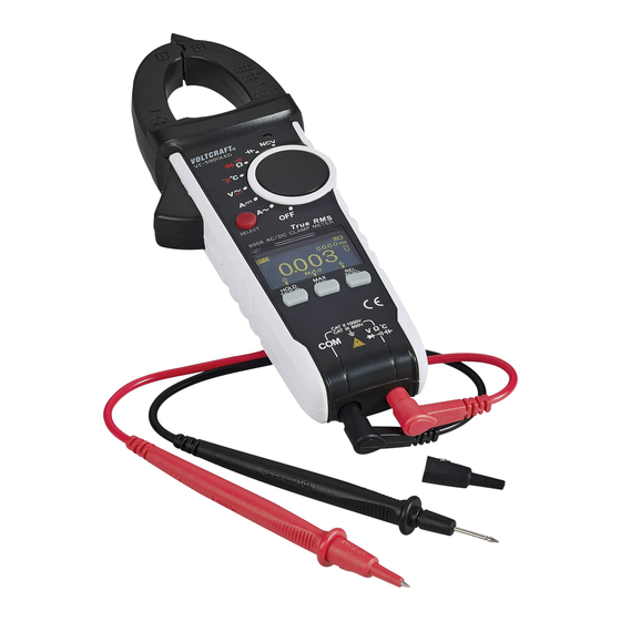
  • Page 82: Élements De Fonctionnement

    3. Élements de fonctionnement...
  • Page 83 1 Sélecteur de câble avec capteur NCV intégré 2 Pince ampèremétrique 3 Affichage du signal NCV 4 Levier d‘ouverture de la pince ampèremétrique 5 Touche SELECT pour le basculement vers une fonction (symboles rouges) 6 Affichage des mesures (écran OLED) 7 Touche de fonction HOLD/SETUP HOLD = fonction pour geler la mesure dans l‘affichage SETUP = fonction de configuration des réglages (Auto-Power-Off, luminosité de l’OLED) 8 T ouche de fonction MAX/MIN pour afficher les valeurs maximales, minimales et moyennes (AVG) 9 Connecteur de mesure COM (potentiel de référence «...
  • Page 84: Contenu D'emballage

    4. Contenu d’emballage • Multimètre numérique avec pince ampèremétrique • 3 piles AAA • 2 fils de mesure de sécurité CAT III • Sonde de température (- 40 à + 230 °C, Type K avec fiche banane 4 mm) • Mode d‘emploi Modes d‘emploi actuels Téléchargez les modes d‘emplois actuels sur le lien www.conrad.com/downloads ou bien scan- nez le code QR représenté. Suivez les indications du site internet. 5.
  • Page 85 Les symboles suivants doivent être respectés : Dans ce mode d’emploi, le symbole avec le point d‘exclamation dans un triangle in- dique des instructions importantes qui doivent être respectées. Le symbole de l’éclair dans un triangle met en garde contre tout risque de décharge électrique ou toute atteinte à...
  • Page 86 Potentiel de terre Pour des raisons de sécurité et d‘homologation, il est interdit de modifier la constructionet/ou de transformer l’appareil. Adressez-vous à un technicien spécialisé si vous avez des doutes concernant la manipulation, la sécurité ou le branchement de l’appareil. Les instruments de mesure et les accessoires ne sont pas des jouets et doivent être tenus hors de portée des enfants ! Dans les installations commerciales et industrielles, les normes de sécurité...
  • Page 87 Évitez l’utilisation à proximité immédiate de : - champs magnétiques ou électromagnétiques puissants ; - antennes émettrices ou générateurs HF. La valeur mesurée pourrait être ainsi faussée. Lorsqu’un fonctionnement sans risque de l’appareil n’est plus possible, il convient de le mettre hors service et de le sécuriser afin d’éviter toute utilisation accidentelle. Il faut prendre en consi- dération qu‘une utilisation sans danger n‘est plus possible lorsque : - l’appareil présente des dommages visibles ;...
  • Page 88: Description Du Produit

    6. Description du produit Les valeurs mesurées sont représentées sur le multimètre (dénommé ci-après DMM pour digital multimeter) dans un affichage numérique OLED auto-lumineux. L‘affichage de la valeur mesu- rée sur le DMM comprend 6000 counts/signes (count = la plus petite valeur). Une mise hors tension automatique permet d’éteindre l‘appareil automatiquement lorsqu’il n‘est pas utilisé...
  • Page 89: Indications Apparaissant À L'écran Et Symboles/Icones

    7. Indications apparaissant à l’écran et symboles/icones Les symboles et indications suivants sont disponibles sur l‘appareil ou sur l‘écran. AUTO Sélection de la gamme de mesure automatique activée SETUP 1/2 Appel de la fonction de réglage de l‘appareil des fonctions 1 et 2 Mise hors tension –...
  • Page 90 Symbole pour le test de diodes. Symbole pour le testeur de continuité acoustique Grandeur alternative pour tension et électricité Grandeur continue pour tension et électricité V, mV Volt (unité de tension électrique) milli volt (exp. -3) A, mA, μA A mpère (unité d’intensité de courant électrique), Milliampère (exp. -3), microampère (exp. -6) Hertz (unité...
  • Page 91: Mode De Mesure

    « OFF ». Éteignez toujours l‘instrument de mesure lorsqu‘il n‘est pas utilisé. Après la mise sous tension, un test de fonctionnement bref est effectué. Lors du test de fonctionnement, « VOLTCRAFT » est affiché. Ce test prend environ 3 secondes et s‘achève par un bip. Avant de pouvoir travailler avec l’instrument de mesure, les piles fournies doivent d’abord être insérées.
  • Page 92: Mesure Du Courant « A

    b) Mesure du courant « A » Ne dépassez jamais les valeurs d’entrée maxi admissibles ! Ne touchez aucun circuit ou aucune partie des circuits en présence de tensions supérieures à 33 V/CA rms ou à 70 V/CC. Danger de mort ! La tension maximale admissible dans le circuit de mesure électrique contre le potentiel terrestre ne doit pas dépasser 1000 V en CAT II et 600 V en CAT III.
  • Page 93 Pour mesurer des courants alternatifs (A ), procédez comme suit : - Allumez le DMM avec le commutateur rotatif (13) ; ensuite, sélectionnez la gamme de me- sure « A » ; sur l’écran d‘affichage, « A » apparaît ainsi que le symbole pour courant alternatif « »...
  • Page 94 Pour mesurer des courants continus (A ), procédez comme suit : - Allumez le DMM avec le commutateur rotatif (13) ; ensuite, sélectionnez la gamme de mesure « A » ; sur l’écran d‘affichage, « A » apparaît ainsi que le symbole pour courant continu « » ; - À cause de la grande sensibilité et du champ magnétique ambiant (p. ex. champ magnétique terrestre, etc.) et avec une pince ampèremétrique fermée dans une gamme de mesure de courant continu, une valeur de courant plus basse sera toujours indiquée ;...
  • Page 95: Mesure De La Tension « V

    c) Mesure de la tension « V » Pour mesurer les tensions alternées « AC » (V), procédez comme suit : - Allumez le DMM et sélectionnez la gamme de mesure « V » ; - E nfichez le cordon de mesure rouge dans le connecteur de me- sure V (10) et le cordon de mesure noir dans le connecteur de mesure COM (9) ;...
  • Page 96: Mesure De La Température

    d) Mesure de la température La sonde de température ne doit être exposée qu’à la température à mesurer pendant la thermométrie. La température de fonctionnement de l’instrument de mesure ne doit pas dépassée ni en dessus ni en dessous des valeurs, sous risque d’avoir des erreurs de mesure.
  • Page 97: Mesure De La Résistance

    e) Mesure de la résistance Assurez-vous que tous les éléments du circuit, tous les circuits, tous les com- posants à mesurer et autres objets de mesure soient impérativement hors ten- sion et déchargés. Pour la mesure de la résistance, procédez comme suit : - Allumez le DMM et sélectionnez la gamme de mesure « Ω » ;...
  • Page 98: Essai De Continuité

    f) Essai de continuité Assurez-vous que tous les éléments du circuit, tous les circuits, tous les com- posants à mesurer et autres objets de mesure soient impérativement hors ten- sion et déchargés. - Allumez le DMM et sélectionnez la gamme de mesure Appuyez sur la touche «...
  • Page 99: Test De Diodes

    g) Test de diodes ; Assurez-vous que tous les éléments du circuit, tous les circuits, tous les com- posants à mesurer et autres objets de mesure soient impérativement hors ten- sion et déchargés. - Allumez le DMM et sélectionnez la gamme de mesure Appuyez deux fois sur la touche «...
  • Page 100: Mesure De La Capacité

    h) Mesure de la capacité Assurez-vous que tous les éléments du circuit, tous les circuits, tous les com- posants à mesurer et autres objets de mesure soient impérativement hors ten- sion et déchargés. Respectez absolument la polarité avec les condensateurs électrolytiques ! - Allumez le DMM et sélectionnez la gamme de mesure - E nfichez le cordon de mesure rouge dans le connecteur de mesure V (10) et le cordon de mesure noir dans le connec-...
  • Page 101: Détection De La Tension Alternée Sans Contact « Ncv

    i) Détection de la tension alternée sans contact « NCV » Le détecteur de tension sert seulement pour des tests rapides et ne remplace jamais une détection de la tension avec contact. Cette méthode de vérification, permettant de tester l’absence de tension afin d’effectuer certains travaux, n’est pas autorisée. Grâce à la fonction de détection NCV (Non Contact Voltage Detection), la présence de tension alternée sur les conducteurs est détectée sans contact.
  • Page 102: Fonctions Supplémentaires

    9. Fonctions supplémentaires Avec les fonctions supplémentaires suivantes, des réglages sur l‘appareil peuvent être effectués ou des fonctions spéciales de mesure utilisées. a) Configuration des réglages de l’appareil Le DMM permet un réglage individuel de la période d’arrêt (de 0 à 30 minutes) pour la fonction automatique de mise hors tension (APO) et la luminosité...
  • Page 103: Fonction De Maintien - Hold

    Luminosité de l‘écran OLED Appuyez sur la touche « SETUP » et maintenez-la pendant env. 2 secondes. Sur l’écran d‘affichage apparaît la fenêtre de configuration « SETUP 1 APO TIME » pour la mise hors tension automatique. Appuyez sur la touche «...
  • Page 104: Fonction Maxi/Mini

    c) Fonction MAXI/MINI La fonction MAX/MIN permet de saisir pendant un relevé de mesure, les valeurs maximale et minimale et éventuellement, de les afficher avec la valeur de mesure (AVG). Après l‘activation de la fonction « MAX/MIN », les valeurs maximale et minimale sont saisies pour la durée de mesure actuelle. En appuyant sur la touche « MAX/MIN » (8), la plage de mesure actuelle est fixée (auto-gamme est désactivée). Le symbole inverse « MAXMIN » apparaît à l‘écran. La valeur maximale est maintenue et affiché en continu sur l‘affichage principal. Cette valeur est reconnaissable grâce au symbole «...
  • Page 105: Fonction Rel

    d) Fonction REL La fonction REL permet de mesurer une valeur de référence afin d´éviter d´éventuelles pertes de lignes telles que les mesures de résistance. Pour cela, la valeur affichée momentanément est mise à zéro. Une nouvelle valeur de référence a été réglée. La valeur de base (différence relative) est affichée sur le petit affichage en haut. En appuyant sur la touche « REL » (11), cette fonction de mesure est activée et la valeur de réfé- rence enregistrée. Sur l’écran d’affichage apparaît « REL ». Appuyez de nouveau sur la touche «...
  • Page 106: Nettoyage Et Entretien

    10. Nettoyage et entretien a) Généralités Afin de garantir la précision du multimètre pendant une longue période, il doit être calibré une fois par an. Hormis un nettoyage occasionnel et un remplacement des piles, l´instrument de mesure ne nécessite aucune maintenance. Les indications concernant le remplacement des piles se trouve à la fin. Contrôlez régulièrement la sécurité technique de l’appareil et des cordons de mesure en vous assurant de l’absence de dommages au niveau du boîtier, de pincement, etc.
  • Page 107: Insertion Et Remplacement Des Piles

    c) Insertion et remplacement des piles Pour faire fonctionner l’instrument de mesure, trois micro-piles de 1,5 volt (p. ex. AAA ou LR03) sont nécessaires. Lors de la première mise en service ou si le symbole de remplacement des piles s‘affiche sur l‘écran, une nouvelle pile entièrement chargée doit être insérée. Le symbole de remplacement des piles a différents niveaux d‘affichage que vous pouvez visua- liser dans le tableau ci-dessous.
  • Page 108 Prière de ne jamais utiliser l‘instrument de mesure lorsqu‘il est ouvert ! DANGER DE MORT ! N e laissez jamais des piles usagées dans l´instrument de mesure, car même les piles protégées contre les fuites peuvent s’oxyder et ainsi libérer des produits chimiques qui nuiront à votre santé ou détruiront l‘appareil. Ne laissez pas traîner négligemment les piles. Il y a un risque qu’elles soient avalées par un enfant ou un animal domestique.
  • Page 109: Élimination

    11. Élimination a) Généralités N’éliminez pas le produit avec les déchets ménagers. Il convient de procéder à l’élimination du produit au terme de sa durée de vie conformément aux prescriptions légales en vigueur ; rapportez-le à un centre de récupération adéquat. Retirez les piles/piles rechargeables insérées et éliminez-les séparément de l’appareil.
  • Page 110: Dépannage

    12. Dépannage Avec le DMM, vous avez acquis un produit à la pointe du développement technique et qui bénéficie d’un fonctionnement fiable. Il est toutefois possible que des problèmes ou des pannes surviennent. C‘est pourquoi nous tenons à décrire ici comment vous pouvez facilement remédier vous-même à...
  • Page 111: Donnees Techniques

    13. Donnees techniques Affichage ............6000 counts (signes) Fréquence des mesures ....... env. 3 mesures/seconde, graphique à barres env. 3 mesures/seconde Méthode de mesure V/AC, A/AC ....TrueRMS (saisie de mesures efficaces vraies) Longueur des cordons de mesure ....chacun d’env. 90 cm Mesure d‘impédance ........> 10 MΩ (gamme V) Ouverture de la pince ampèremétrique ..
  • Page 112 Courant alternatif Plage Précision Résolution 60,00 A 0,01 A ±(2,5% + 5) 600,0 A 0,1 A Gamme de fréquences 50 - 60 Hz ; protection contre la surcharge 750 V, 1000 A Erreur de positionnement de mesure : écart de précision pour un endroit de mesure non-centré...
  • Page 113 Tension alternée Plage Précision Résolution 6,000 V 0,001 V 60,00 V ±(1,2% + 3) 0,01 V 600,0 V 0,1 V 750 V ±(1,5% + 5) Gamme de fréquences de 45 à 400 Hz ; protection contre la surcharge 750 V ; impédance : 10 MΩ...
  • Page 114 Température Plage Précision* Résolution -40 jusqu’à + 0 °C ±(2,5% + 5) 0 jusqu’ à +400 °C 1 °C +400 jusqu’ à +1000 °C ±(3,0% + 5) -40 jusqu’ à +32 °F ±(2,5% + 11) +32 jusqu’ à +752 °F 1 °F +752 jusqu’...
  • Page 115 Capacité Plage Précision Résolution 60,00 nF ±(4% + 20) 0,01 nF 600,0 nF 0,1 nF 6,000 μF 0,001 μF 60,00 μF 0,01 μF 600,0 μF 0,1 μF 6,000 mF ±(8,0% + 20) 0,001 mF 60,00 mF Non spécifié 0,01 mF Protection contre la surcharge 1000 V Test de diodes ; Tension d‘essai Résolution env.
  • Page 116 Inhoudsopgave Pagina 1. Inleiding ...........................117 2. Beoogd gebruik .......................118 3. Bedieningselementen ......................120 4. Leveringsomvang ......................122 5. Veiligheidsinstructies .......................122 6. Productbeschrijving ......................126 7. Weergave-elementen en symbolen .................127 8. Meetprocedure ........................129 a) De multimeter inschakelen ..................129 b) Stroommeting “A” .....................130 c) Spanningsmeting “V” ....................133 d) Temperatuurmeting ....................134 e) Weerstandsmeting ....................135 Continuïteitstest ......................136...
  • Page 117: Inleiding

    ® lijkste taken probleemloos uitvoeren. Voltcraft biedt u betrouwbare technologieën met een uit- ® stekende prijs-/prestatieverhouding. We zijn ervan overtuigd: Uw keuze voor Voltcraft is het begin van een lange en vruchtbare ® samenwerking. Veel plezier met uw Voltcraft product! ®...
  • Page 118: Beoogd Gebruik

    2. Beoogd gebruik - Het meten en weergeven van elektrische parameters in de meetcategorie CAT III tot max. 600 V of CAT II tot max. 1000 V ten opzichte van het aardpotentiaal en in overeenstemming met EN 61010-1 en alle lagere categorieën. De multimeter mag niet worden gebruik in de meetcategorie CAT IV.
  • Page 119 Gebruik de multimeter niet wanneer de behuizing of het batterijvak open is of als het batterij- deksel ontbreekt. Metingen in mogelijke explosieve ruimten (Ex), in vochtige ruimten of in ongunstige omgeving- somstandigheden zijn niet toegestaan. Ongunstige omgevingsomstandigheden zijn: vochtige omstandigheden of hoge vochtigheid, stof of brandbare gassen, dampen of oplosmiddelen, maar tevens onweer of gelijksoortige omstandigheden zoals sterk elektrostatische velden, etc.
  • Page 120: Bedieningselementen

    3. Bedieningselementen...
  • Page 121 1. Kabelkiezer met ingebouwde NCV-sensor 2. Stroomtang 3. Weergave van NCV-signaal 4. Hendel voor openen van stroomtang 5. SELECT toets voor functies (rode symbolen) 6. Display voor weergave van metingen (OLED) 7. HOLD/SETUP toets HOLD = Zet de huidige meetwaarde vast op het display SETUP = Toegang tot de basisinstellingen (automatische uitschakeling, OLED helderheid) 8.
  • Page 122: Leveringsomvang

    4. Leveringsomvang • Digitale multimeter/stroomtang • 3 x AAA batterijen • 2x CAT III veiligheidsmeetkabels • Temperatuursensor (-40 tot +230 °C type K met 4 mm banaanstekker) • Gebruiksaanwijzing Actuele gebruiksaanwijzingen Download de actuele gebruiksaanwijzingen via de link www.conrad.com/downloads of scan ze met behulp van de afgebeelde QR-code.
  • Page 123 Houd rekening met de volgende symbolen: Een uitroepteken in een driehoek wijst op belangrijke informatie in deze gebruiksaan- wijzing die in elk geval nageleefd moet worden. Een bliksemschicht in een driehoek waarschuwt voor gevaar op elektrische schokken of beschadiging aan de elektrische beveiliging van het apparaat. Een bliksemschicht in een vierkant geeft aan dat het apparaat gebruikt kan worden om metingen op ongeïsoleerde, gevaarlijke geleiders onder stroom uit te voeren en waarschuwt voor mogelijke gevaren.
  • Page 124 Op grond van veiligheids- en goedkeuringsoverwegingen is het eigenhandig ombouwen of ver- anderen van het product verboden. Raadpleeg een deskundige als u twijfelt over de juiste werking, veiligheid of verbinding van de multimeter. Meetinstrumenten en toebehoren zijn geen speelgoed en moeten uit de buurt van kinderen worden gehouden! In commerciële instellingen moet de hand worden gehouden aan de ongevallenpreventievoor- schriften van het Verbond van Commerciële Bedrijfsverenigingen voor Elektrische Installaties...
  • Page 125 Gebruik het product niet in de directe nabijheid van: - sterke magnetische of elektromagnetische velden - zendmasten of HF-generatoren. De gemeten waarde kan daardoor onjuist zijn. Als u een reden hebt om te denken dat het apparaat niet langer op een veilige manier gebruikt kan worden, haal de stekker onmiddellijk uit het stopcontact en zorg dat het apparaat niet per ongeluk ingeschakeld kan worden.
  • Page 126: Productbeschrijving

    6. Productbeschrijving De digitale multimeter (hierna DMM genoemd) is voorzien van een verlicht digitaal OLED-dis- play om de metingen weer te geven. Het meetdisplay van de DDM bestaat uit 6000 counts (count = laagste displaywaarde). Een automatische uitschakelfunctie schakelt het apparaat na een bepaalde periode van inacti- viteit automatisch uit.
  • Page 127: Weergave-Elementen En Symbolen

    7. Weergave-elementen en symbolen De volgende symbolen en aanduidingen zijn zichtbaar op het apparaat of in het display. AUTO Automatische bereikkeuze is actief SETUP 1/2 Toegang tot apparaatinstellingen en weergave van functie 1 en 2 Automatische uitschakeling is actief APO TIME Uitschakeltijd in minuten (m) Schakelaar positie uit of functie gedeactiveerd OLED BRIGHT %...
  • Page 128 Symbool voor akoestische continuïteitscontrole Wisselspanning en -stroom Gelijkspanning en -stroom V, mV Volt (eenheid van elektrisch potentiaal), millivolt (exp -3) A, mA, μA Ampère (eenheid voor elektrische stroom), milliampère (exp -3), microampère (exp -6) Hertz (eenheid van elektrische frequentie) °C, °F Eenheid van temperatuur (Celsius = Europees, Fahrenheit = empirisch) Ω, kΩ, MΩ...
  • Page 129: Meetprocedure

    Schakel de multimeter altijd uit wanneer niet in gebruik. Na inschakeling vindt er een korte functietest plaats. Tijdens de functietest geeft het display “VOLTCRAFT” weer. De test duurt circa 3 seconden en eindigt met een pieptoon. Voordat u de multimeter kunt gebruiken, installeer de meegeleverde batterijen.
  • Page 130: Stroommeting "A

    b) Stroommeting “A” Overschrijd nooit de maximale toegestane invoerwaarden. Raak geen schake- lingen of aansluitpunten aan als daar hogere spanningen dan 33 V/Acrms of 70 V/DC op kunnen staan. Risico op dodelijk letsel! De maximale toegestane spanning in de te meten stroomkring ten opzichte van het aardpotentiaal mag de 1000 V in CAT II of 600 V in CAT III niet overschrijden.
  • Page 131 Voer de volgende procedure uit om wisselstroom (A ) te meten: - Schakel de DMM in met behulp van de draaischakelaar (13) en selecteer het meetbereik “A ”. “A” en het symbool voor wisselstroom “ ” worden op het display weergegeven. - In het wisselstroom-meetbereik wordt het display automatisch op nul ingesteld zodra de tang wordt gesloten.
  • Page 132 Voer de volgende procedure uit om gelijkstroom (A ) te meten: - Schakel de DMM in met behulp van de draaischakelaar (13) en selecteer het meetbereik “A ”. “A” en het symbool voor gelijkstroom “ ” worden op het display weergegeven. - In het gelijkstroom-meetbereik is het mogelijk dat een lage stroom in het display wordt weergegeven omwille van de hoge gevoeligheid en het omringend magnetisch veld (i.e.
  • Page 133: Spanningsmeting "V

    c) Spanningsmeting “V” Voer de volgende procedure uit om wisselspanning “AC” (V ) te meten: - Schakel de DMM in en selecteer het meetbereik “V ”. - Breng de rode meetkabel in de V-meetaansluiting (10) en de zwarte meetkabel in de COM-meetaansluiting (9). - Verbind de meetsondes met het meetobject (generator, voedingsspanning, etc.).
  • Page 134: Temperatuurmeting

    d) Temperatuurmeting Tijdens het meten van de temperatuur mag enkel de temperatuursensor aan de te meten temperatuur onderhevig worden gesteld. Over- of onderschrijd de bedrijfstemperatuur van de DMM niet om foutieve metingen te vermijden. De contact-temperatuursensor mag alleen op spanningsvrije oppervlakken worden gebruikt.
  • Page 135: Weerstandsmeting

    e) Weerstandsmeting Zorg dat de te meten stroomkringcomponenten, stroomkringen en componen- ten of andere meetobjecten spanningsvrij en ontladen zijn. Voer volgende procedure uit om de weerstand te meten: - Schakel de DMM in en selecteer het meetbereik “Ω”. - B reng de rode meetkabel in de Ω-meetaansluiting (10) en de zwarte meetkabel in de COM-meetaansluiting (9). - Controleer de meetkabels op continuïteit door de meet- sondes met elkaar te verbinden.
  • Page 136: Continuïteitstest

    f) Continuïteitstest Zorg dat de te meten stroomkringcomponenten, stroomkringen en componen- ten of andere meetobjecten spanningsvrij en ontladen zijn. - Schakel de DMM in en selecteer het meetbereik Druk op de SELECT toets om naar het juiste meetbe- reik te schakelen. Het display geeft het symbool voor continuïteitstest weer.
  • Page 137: Diodetest

    g) Diodetest Zorg dat de te meten stroomkringcomponenten, stroomkringen en componen- ten of andere meetobjecten spanningsvrij en ontladen zijn. - Schakel de DMM in en selecteer het meetbereik Druk tweemaal op de SELECT toets om naar de juiste meetfunctie te schakelen. Het display geeft het symbool voor diodetest weer.
  • Page 138: Capaciteitsmeting

    h) Capaciteitsmeting Zorg dat de te meten stroomkringcomponenten, stroomkringen en componen- ten of andere meetobjecten spanningsvrij en ontladen zijn. In geval van elektrolytische condensatoren, houd rekening met de juiste polari- teit. - Schakel de DMM in en selecteer het meetbereik - Breng de rode meetkabel in de V-meetaansluiting (10) en de zwarte meetkabel in de COM-meetaansluiting (9).
  • Page 139: Contactloze Spanningsdetectie "Ncv

    i) Contactloze spanningsdetectie “NCV” De spanningsdetector dient om snel te meten en is geen vervanging voor de- tectie van contact-spanningsdetectie. Deze methode is niet toegestaan voor het controleren op afwezigheid van spanning om bepaalde werken uit te voeren. De NCV-functie (contactloze spanningsdetectie) wordt gebruikt om de aanwezigheid van wissel- spanning in geleiders te detecteren.
  • Page 140: Extra Functies

    9. Extra functies De volgende extra functies kunnen worden gebruikt om apparaatinstellingen uit te voeren of om speciale meetfuncties te gebruiken. a) SETUP-apparaatinstellingen De DMM stelt u in staat om een uitschakeltijd (0-30 minuten) voor de automatische uitscha- kelfunctie (APO) en de helderheid van het OLED-display (0-100%) in te stellen. Automatische uitschakeling “APO”...
  • Page 141: Hold-Functie

    Helderheid van OLED-display Druk en houd de SETUP toets circa 2 seconden vast. Het display toont de setupvensters “SETUP 1 APO TIME” voor automa- tische uitschakeling. Druk op de SELECT toets (5) om naar het menu “SETUP 2 OLED BRIGHT” te schakelen. Gebruik de MAX MIN toets (8) om de waarde in stappen van 10% te verhogen.
  • Page 142: Max/Min-Functie

    c) MAX/MIN-functie De MAX/MIN-functie stelt u in staat om de maximum, minimum en gemiddelde (AVG) waarde van een meting te registreren. De maximum en minimum waarde voor de huidige meting worden geregistreerd nadat de MAX/MIN-functie geactiveerd is. Druk op de MAX/MIN-toets (8) om het huidig meetbereik vast te zetten (automatisch bereik is gedeactiveerd).
  • Page 143: Rel-Functie

    d) REL-functie Gebruik de REL-functie om relatieve waardemetingen uit te voeren zodat bijv. lijnverliezen tij- dens het meten van weerstand worden vermeden. De functie zet de huidige displaywaarde terug op nul. Een nieuwe referentiewaarde is nu ingesteld. Het bovenste kleiner display toont de basiswaarde (relatieve verschil).
  • Page 144: Onderhoud En Reiniging

    10. Onderhoud en reiniging a) Algemeen Kalibreer uw multimeter minstens eenmaal per jaar om een optimale meetnauwkeurigheid te waarborgen. Het product is, behalve een regelmatige reiniging en het vervangen van de batterijen, onder- houdsvrij. Voor instructies over hoe de batterijen te vervangen, zie hieronder. Controleer regelmatig de technische veiligheid van het apparaat en de meetka- bels –...
  • Page 145: De Batterijen Installeren En Vervangen

    c) De batterijen installeren en vervangen Het apparaat werkt op drie 1,5 V microbatterijen (i.e. AAA of LR03). Voor ingebruikname of wanneer het batterij vervangen-symbool in het display verschijnt, installeer nieuwe, volle batterijen. Het batterij vervangen-symbool heeft verschillende displayniveaus, zie onderstaande tabel: Symbool Batterijspanning Resultaat...
  • Page 146 Gebruik de meter nooit met een open behuizing !RISICO OP DODELIJK LETSEL! Laat geen gebruikte batterijen in de multimeter achter. Zelfs lekbestendige bat- terijen kunnen roesten en chemische lekken veroorzaken die schadelijk voor de gezondheid zijn en het apparaat kunnen beschadigen. Laat batterijen niet rondslingeren.
  • Page 147: Verwijdering

    11. Verwijdering a) Algemeen Het product hoort niet bij het huishoudelijke afval. Het product dient aan het einde van zijn levensduur volgens de geldende wettelijke voorschriften te worden verwijderd. Lever het bijv. in bij het betreffende inzamelpunt. Verwijder de geplaatste batterijen of accu’s en voer deze gescheiden van het product af. b) Verwijdering van gebruikte accu’s Als eindverbruiker bent u conform de KCA-voorschriften wettelijk verplicht om alle gebruikte accu’s in te leveren;...
  • Page 148: Probleemoplossing

    12. Probleemoplossing Met de DMM hebt u een betrouwbaar product gekocht dat met gebruik van spitstechno- logie werd ontwikkeld. Fouten en storingen kunnen zich echter voordoen. Bekijk het volgende als er problemen optreden: Leef altijd de veiligheidsinstructies na! Fout Mogelijke oorzaak Mogelijke oplossing De multimeter Zijn de batterijen leeg?
  • Page 149: Technische Gegevens

    13. Technische gegevens Weergave ........6000 counts (cijfers) Meetsnelheid ........circa 3 metingen/seconden, staafdiagram circa 3 metingen/ seconde Meetprocedures V/AC, A/AC ..Echte RMS Lengte meetkabel ......elk circa 90 cm Meetimpedantie ......>10 MΩ (V-bereik) Opening stroomtang .......max. 30 mm Afstand meetaansluiting ....19 mm Automatische uitschakeling ...0 - 30 minuten (instelbaar in stappen van 1 minuut) Stroomvoorziening ......3 microbatterijen (1,5 V, AAA of LR03) Bedrijfsomstandigheden ....
  • Page 150 Wisselstroom Bereik Nauwkeurigheid Resolutie 60,00 A 0,01 A ±(2,5% + 5) 600,0 A 0,1 A Frequentiebereik 50 - 60 Hz; Beveiliging tegen overbelasting 750 V, 1000 A Meetpuntfout: nauwkeurigheidsafwijking in geval van niet gecentreerd meetpunt: ±1 Wanneer de invoer wisselstroom ≥10 A frequentie wordt weergegeven Echte RMS crestfactor (CF): max. 3,0 CF >1,0 - 2.0 + 3% CF >2,0 - 2.5...
  • Page 151 AC-spanning Bereik Nauwkeurigheid Resolutie 6,000 V 0,001 V 60,00 V ±(1,2% + 3) 0,01 V 600,0 V 0,1 V 750 V ±(1,5% + 5) Frequentiebereik 45 - 400 Hz; Beveiliging tegen overbelasting 750 V, Weerstand: 10 MΩ Wanneer de invoer wisselspanning ≥100 mV RMS-frequentie wordt weergegeven Echte RMS crestfactor (CF): max. 3,0 CF >1,0 – 2,0 + 3% CF >2,0 – 2,5 + 5% CF >2,5 –...
  • Page 152 Temperatuur Bereik Nauwkeurigheid* Resolutie -40 tot 0 °C 1 °C ±(2,5% + 5) 0 tot +400 °C +400 tot +1000 °C ±(3,0% + 5) -40 tot +32 °F 1 °F ±(2,5% + 11) +32 tot +752 °F +752 tot +1832 °F ±(3,0% + 11) * zonder sensortolerantie Weerstand...
  • Page 153 Capaciteit Bereik Nauwkeurigheid Resolutie 60,00 nF ±(4% + 20) 0,01 nF 600,0 nF 0,1 nF 6,000 μF 0,001 μF 60,00 μF 0,01 μF 600,0 μF 0,1 μF 6,000 mF ±(8,0% + 20) 0,001 mF 60,00 mF Niet gespecificeerd 0,01 mF Beveiliging tegen overbelasting 1000V Diodetest Meetspanning Resolutie circa 3,3 V 0,001 V Beveiliging tegen overbelasting: 1000 V...
  • Page 156 Dies ist eine Publikation der Conrad Electronic SE, Klaus-Conrad-Str. 1, D-92240 Hirschau (www.conrad.com). Alle Rechte einschließlich Übersetzung vorbehalten. Reproduktionen jeder Art, z.B. Fotokopie, Mikroverfilmung, oder die Erfassung in elektronischen Daten- verarbeitungsanlagen, bedürfen der schriftlichen Genehmigung des Herausgebers. Nachdruck, auch auszugsweise, verboten. Die Publikation entspricht dem technischen Stand bei Drucklegung.

Ce manuel est également adapté pour:

1181861

Table des Matières