Table des Matières
Publicité
Les langues disponibles
Les langues disponibles
Liens rapides
Publicité
Table des Matières

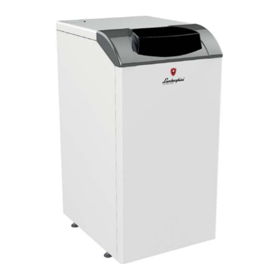
Manuels Connexes pour Lamborghini Caloreclima ERA F 23 D


Sommaire des Matières pour Lamborghini Caloreclima ERA F 23 D
- Page 1 ERA F D IT - ISTRUZIONE PER L’USO L'INSTALLAZIONE E LA MANUTENZIONE ES - INSTRUCCIONES DE USO, INSTALACIÓN Y MANTENIMIENTO TR - KULLANMA, KURULUM VE BAK M TALIMATLAR EN - INSTRUCTIONS FOR USE, INSTALLATION AND MAINTENANCE FR - INSTRUCTIONS D'UTILISATION, D'INSTALLATION ET D'ENTRETIEN UK -...
-
Page 34: Généralités
ERA F D 17 = Elle est affichée en cas de branchement de la sonde extérieure ou de la chro- nocommande à distance (options) 18 = Température ambiante (avec chronocommande à distance, option) 19 = Indication "Brûleur allumé" 20 = Indication "fonctionnement hors-gel"... -
Page 35: Température Évolutive
ERA F D Extinction prolongée Courbe de compensation et déplacement des courbes Pour éteindre la chaudière, il faut : Appuyer une fois sur la touche mode (rep. 10 - fig. 1) pour afficher la courbe de com- pensation actuelle (fig. 9). Il est possible de la modifier à l'aide des touches eau chaude •... -
Page 36: Raccordements Hydrauliques
ERA F D Réglage de la pression hydraulique de l'installation Raccordement à un ballon servant à la production d'eau chaude sanitaire La pression de remplissage avec l'installation à froid (lue sur l'afficheur) doit être d'envi- La carte électronique de l'appareil est prévue pour la gestion d'un ballon externe pour la ron 1,0 bar. -
Page 37: Conduits D'air/De Fumée
ERA F D Accès au bornier électrique Transformation gaz d'alimentation Dévisser les deux vis “A” situées sur la partie supérieure du tableau et déposer le volet. L'appareil peut fonctionner au gaz naturel (G20-G25) ou au gaz liquide (G30-G31) et est prédisposé... -
Page 38: Entretien
ERA F D Allumage Avant d'effectuer une quelconque opération à l'intérieur de la chaudière, la mettre hors tension et fermer le robinet du gaz en amont Ouvrir les vannes d'arrêt du combustible. Mettre l'appareil sous tension. Propreté de la chaudière et de la cheminée Pendant les 120 secondes qui suivent, l'afficheur visualise FH (cycle de purge de l'air du circuit de chauffage). -
Page 39: Groupe Brûleur Pilote
ERA F D Groupe brûleur pilote 4.4 Dépannage Diagnostic La chaudière est équipée d'un dispositif d'autodiagnostic avancé. En cas d'anomalies de fonctionnement de la chaudière, l'affichage clignote avec le symbole d'anomalie (rep. 22 - fig. 1) indiquant le code de l'anomalie. Il y a des anomalies qui provoquent des blocages permanents (indiqués par la lettre «... -
Page 40: Perte De Charge
49.5 Puissance thermique mini 10.1 14.9 19.7 Puissance thermique maxi chauffage 23.0 32.0 45.0 fig. 22 - Dimensions et raccords mod. ERA F 23 D Puissance thermique mini chauffage 13.0 17.2 Rendement Pmax (80-60 °C) 90.9 91.7 90.9 Rendement 30% 91.3... -
Page 41: Schéma Électrique
ERA F D 5.4 Schéma électrique T° T° fig. 25 - Schéma électrique Circulateur circuit chauffage (option) Sonde température eau chaude sanitaire (option) Vanne à gaz Thermostat d'ambiance (non fourni) Électrode d'allumage Électrode de détection Thermostat fumées Circulateur eau chaude sanitaire (option) Sonde extérieure (non fournie) Unité... - Page 42 ERA F D 20 = 21 = 22 = 23 = 24 = 25 = • 26 = • 27 = - Estate • • • ’ • . 2 - • • • sez. 3.3. • • • • ’...
- Page 43 ERA F D . 10 - . 1) ’ . 9), . 1). estate/inverno ( . 6 - . 1) . 11). - Estate ( . 27 - . 1): . 9 - . 1) Estate ( estate/inverno ( . 12), .
- Page 44 ERA F D F37 ( . 13). . 14 ( cap. 5.4. LAMBORGHINI. . 13 - . 14 - i ( i i ’ . 25), i ’ ’ cap. 5.1 25° Fr (1°F = 10 CaCO3), 15°F 236/88 ’ "Y", ’...
- Page 45 ERA F D . 17. i ’ . 17), . 17), i cap. 5.2. i ’ “A” (G20-G25) (G30-G31), cap. 5, . 17). “ ” (G20-G25 . 17 G30-G31 . 17); . 15 - B11BS F04 ( . cap. 4.4). .
- Page 46 ERA F D ’ . 19) ’ • • • • • • ’ • RESET. • " • ". • • • • • • cap. 5.3. • • • • • . 19 - • . 21). • •...
- Page 48 3000 3500 4000 4500 5000 5500 . 24 - 25.3 34.9 49.5 10.1 14.9 19.7 . 22 - . ERA F 23 D 23.0 32.0 45.0 13.0 17.2 i Pmax (80-60°C) 90.9 91.7 90.9 i 30% 91.3 91.5 91.6 Ø...
- Page 49 ERA F D T° T° . 25 - ’ cod. 3541O210 - Rev. 01 - 03/2018...
- Page 52 BRUCIATORI CALDAIE MURALI E TERRA A GAS GRUPPI TERMICI IN GHISA E IN ACCIAIO GENERATORI DI ARIA CALDA TRATTAMENTO ACQUA CONDIZIONAMENTO italya’da üretilmi tir...