Uline METRO Serie Instructions De Montage
Masquer les pouces
Voir aussi pour METRO Serie:
- Instructions de montage (18 pages) ,
- Instructions d'installation (15 pages) ,
- Instructions d'assemblage (6 pages)
Publicité
Les langues disponibles
Les langues disponibles
Liens rapides
METRO COLLECTION –
CONFERENCE TABLES
TOOLS NEEDED
Phillips
Screwdriver
A
Adjustable Glide
PART
Adjustable Glide
Bolt
Bolt
Bolt
Bracket
NOTE: Count and inspect all pieces before
disposing of any carton or packing materials.
NOTE: Assemble unit on a smooth, non-marring
surface to prevent scratching.
NOTE: Tighten all bolts using
4 mm Allen wrench or drill.
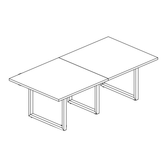
96 x 48'' TABLE
1. Attach two adjustable glides (A) to the bottom
corners of each leg frame. (See Figure 1)
NOTE: End leg frames are wider than
center leg frames.
PAGE 1 OF 15
1-800-295-5510
uline.com
Drill
4 mm Allen Wrench
(Optional)
(Included)
B
M6 x 55 mm Bolt
SIZE
96
M8 x 35 mm
M6 x 55 mm
M6 x 25 mm
M6 x 15 mm
120 x 50 x 3 mm
Three Person Assembly
Recommended
PARTS
C
M6 x 25 mm Bolt
M6 x 15 mm Bolt
QTY.
48" TABLE
144
x
x
6
12
20
16
2
ASSEMBLY
Figure 1
A
Para Español, vea páginas 6-10.
Pour le français, consulter les pages 11-15.
D
E
48" TABLE
192
48" TABLE
x
8
10
18
24
28
36
32
48
4
6
Leg Frame
Bracket
0123 IH-10276
Publicité

Manuels Connexes pour Uline METRO Serie


Sommaire des Matières pour Uline METRO Serie
- Page 1 Para Español, vea páginas 6-10. Pour le français, consulter les pages 11-15. 1-800-295-5510 uline.com METRO COLLECTION – CONFERENCE TABLES TOOLS NEEDED Three Person Assembly Recommended Drill 4 mm Allen Wrench Phillips (Optional) (Included) Screwdriver PARTS Adjustable Glide M6 x 55 mm Bolt...
- Page 2 ASSEMBLY CONTINUED 2. Align holes on end of support bar with top of 4. Attach bracket (E) to underside of tabletop end leg frame and center leg frame. Attach using on the outside of center leg frame using eight five M6 x 25 mm bolts (C). Repeat for remaining M6 x 15 mm bolts (D).
- Page 3 ASSEMBLY CONTINUED 144 x 48", 192 x 48" TABLES NOTE: For 192 x 48" table, add an extra center leg frame and two long support bars during 1. Attach two adjustable glides (A) to the bottom this step. Attach using 4 M6 x 25 mm bolts (C). corners of each leg frame.
- Page 4 ASSEMBLY CONTINUED 4. Place tabletops over assembled frame. Align 5. Attach brackets (E) to underside of tabletops on the pre-drilled holes in tabletop with holes on support outside of center leg frames using eight M6 x 15 mm bars. Attach using 18 M6 x 55 mm bolts (B). bolts (D) per bracket.
- Page 5 (F) using M3 x 8 mm bolts (I) to secure. Attach L-brackets to underside of tabletop Figure 12 using ST3.5 x 12 mm screws (K). Repeat for opposite side of power center. (See Figure 11) Figure 11 1-800-295-5510 uline.com PAGE 5 OF 15 0123 IH-10276...
- Page 6 800-295-5510 uline.mx COLECCIÓN METROPOLITANA – MESA DE OFICINA HERRAMIENTAS NECESARIAS Se Recomienda Armar Entre Tres Personas Taladro Llave Allen de 4 mm Desarmador (Opcional) (Incluida) de Cruz PARTES Tapa Niveladora Perno M6 x 55 mm Perno M6 x 25 mm...
- Page 7 CONTINUACIÓN DEL ENSAMBLE 2. Alinee los orificios del extremo de la barra de 4. Fije el soporte (E) por debajo de la cubierta de la soporte con la parte superior del armazón de la parte externa de la pata central utilizando ocho pata del extremo y el armazón de la pata central.
- Page 8 CONTINUACIÓN DEL ENSAMBLE MESAS DE 144 x 48", 192 x 48 NOTA: Para la mesa de 192 x 48", agregue un armazón de pata central y dos barras largas Fije dos tapas niveladoras (A) a las esquinas de soporte adicionales en este paso. Fije inferiores de cada armazón de la pata.
- Page 9 CONTINUACIÓN DEL ENSAMBLE 4. Coloque las cubiertas sobre el marco ensamblado. 5. Fije los soportes (E) por debajo de las cubiertas en Alinee los orificios preperforados de la cubierta con la parte externa del armazón de la pata central los orificios de las barras de soporte. Fije utilizando utilizando ocho tornillos de M6 x 15 mm (D) por 18 pernos M6 x 55 mm (B).
- Page 10 M3 x 8 mm (I) para asegurarlo. Fije los Soportes en L a la parte inferior de la cubierta utilizando tornillos Diagrama 12 ST3.5 x 12 mm (K). Repita la operación en el lado opuesto del multicontacto. (Vea Diagrama 11) Diagrama 11 800-295-5510 uline.mx PAGE 10 OF 15 0123 IH-10276...
- Page 11 1-800-295-5510 uline.ca COLLECTION METRO – TABLES DE CONFÉRENCE OUTILS REQUIS Montage à trois personnes recommandé Perceuse Clé Allen de 4 mm Tournevis (optionnel) (inclus) cruciforme PIÈCES Patin réglable Boulon M6 x 55 mm Boulon M6 x 25 mm Boulon M6 x 15 mm Support QTÉ...
- Page 12 MONTAGE SUITE 2. Alignez les trous situés aux extrémités de la barre 4. Fixez le support (E) sous la surface de table sur la de support sur le cadre de pied d'extrémité et sur partie extérieure du cadre de pied central avec le cadre de pied central.
- Page 13 MONTAGE SUITE TABLES DE 144 x 48 PO ET DE 192 x 48 PO REMARQUE : Pour les table de 192 x 48 po, ajoutez durant cette étape un autre cadre Fixez deux patins réglables (A) aux coins inférieurs de pied central et deux autres barres longues de chaque cadre de pied.
- Page 14 MONTAGE SUITE 4. Placez les surfaces de table sur le cadre assemblé. 5. Fixez les supports (E) sous les surfaces de table sur la Alignez les trous prépercés des surfaces de table partie extérieure des cadres de pied centraux avec sur ceux des barres de support.
- Page 15 M3 x 8 mm (I). Fixez les supports en L sous la surface de table avec des vis ST3.5 x 12 mm (K). Répétez l'opération de l'autre côté du système d'alimentation. (Voir Figure 11) Figure 11 1-800-295-5510 uline.ca PAGE 15 OF 15 0123 IH-10276...