Publicité
Les langues disponibles
Les langues disponibles
Liens rapides
H-9409
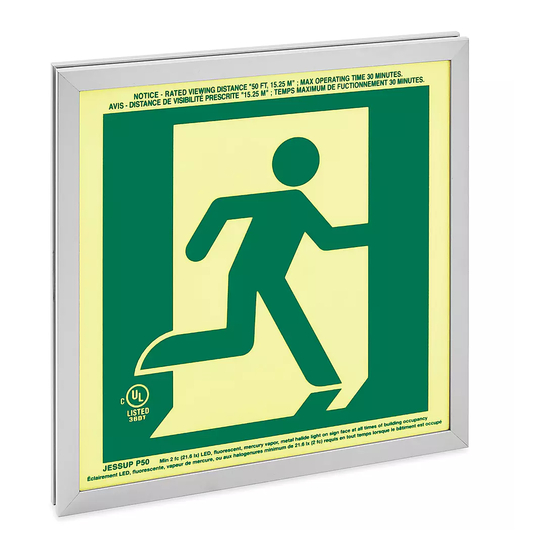
GLO BRITE
RUNNING
®
MAN SIGN – SINGLE SIDED
TOOLS NEEDED
Phillips Screwdriver
Sign x 1
• The sign should be charged with an external
illumination source for a minimum of 60 minutes to
obtain full operational conditions.
• The sign should be mounted in a manner that
ensures rigidity and mechanical sufficiency.
• External illumination source must be reliable and
supplied by a circuit, not controlled by automatic
timers or sensors, and must have controls that are
accessible only to authorized personnel.
• External illumination source is to be energized at all
times during building occupancy.
• Lighting levels on the sign face should be confirmed
after any change in external lighting types or levels.
Sign is designed to operate automatically. Charging
light source must illuminate face of sign in accordance
with at least 21.6 lux of LED, fluorescent, metal halide
or mercury vapor light at all times during building
occupancy to ensure that the sign will remain legible for
at least 30 minutes.
PAGE 1 OF 9
1-800-295-5510
uline.com
Drill
Mounting Bracket x 1
OPERATION
Level
PARTS
Screw x 1
Anchor x 4
(mounting hardware)
SAFETY
• It is recommended that periodic visibility tests be
performed in accordance with all applicable codes.
• Install this sign indoors only, where not exposed to
direct sunlight, liquid spray or temperatures outside
the range of 50°-104°F.
• Cleaning the sign face with a damp cloth is
recommended during monthly inspections.
• When a retrofit involves the replacement of existing
electric exit signs, the electric junction box must be
sealed with an approved blank cover plate before
installing.
Para Español, vea páginas 4-6.
Pour le français, consulter les pages 7-9.
Screw x 4
(mounting hardware)
1122 IH-9409
Publicité

Manuels Connexes pour Uline Glo Brite H-9409

Sommaire des Matières pour Uline Glo Brite H-9409
- Page 1 Para Español, vea páginas 4-6. Pour le français, consulter les pages 7-9. H-9409 1-800-295-5510 uline.com GLO BRITE RUNNING ® MAN SIGN – SINGLE SIDED TOOLS NEEDED Level Phillips Screwdriver Drill PARTS Sign x 1 Mounting Bracket x 1 Screw x 1...
- Page 2 INSTALLATION • When installing into drywall or concrete block, use the bracket in the desired location on the wall or expansion sets to ensure a firm grip. ceiling. All clearances should then be confirmed as acceptable prior to the mounting bracket being •...
- Page 3 5. Insert provided screw into mounting bracket center hole and secure. Fully tighten. (See Figure 8) 6. Put top channel back on with the two screws that were removed in Step 3. (See Figure 8) 1-800-295-5510 uline.com PAGE 3 OF 9 1122 IH-9409...
- Page 4 H-9409 800-295-5510 uline.mx GLO BRITE HOMBRE ® CORRIENDO – UN LADO HERRAMIENTAS NECESARIAS Desarmador de Cruz Taladro Nivel PARTES 1 Señalamiento 1 Soporte de Instalación 1 Tornillo 4 Anclajes 4 Tornillos (tornillería de instalación) (tornillería de instalación) SEGURIDAD • Se debe cargar el señalamiento por medio de •...
- Page 5 INSTALACIÓN • Al instalar en mampostería o bloque de concreto, ensamblado en el soporte de instalación y use los sets de expansión para asegurar un agarre sosteniendo el soporte en la ubicación deseada en firme. la pared o el techo. Todo el espacio libre se debe confirmar como aceptable antes de fijar el soporte •...
- Page 6 Apriete por completo. (Vea Diagrama 8) 6. Vuelva a colocar el canal superior con los dos tornillos que retiró en el Paso 3. (Vea Diagrama 8) 800-295-5510 uline.mx PAGE 6 OF 9 1122 IH-9409...
- Page 7 H-9409 1-800-295-5510 uline.ca GLO BRITE – ENSEIGNE DE SORTIE – HOMME QUI COURT, UNE FACE OUTILS REQUIS Tournevis cruciforme Perceuse Niveau à bulles PIÈCES Enseigne x 1 Support de fixation x 1 Vis x 1 Ancrage x 4 Vis x 4 (matériel d'installation)
- Page 8 INSTALLATION • Pour une installation sur une cloison sèche ou un dans le support de fixation et en maintenant le bloc en béton, utilisez un ensemble d'ancrage support à l'emplacement souhaité sur le mur ou d'extension pour assurer une prise ferme. le plafond.
- Page 9 5. Insérez la vis fournie dans le trou central du support de fixation et fixez-la. Serrez fermement. (Voir Figure 8) 6. Remettez le profilé supérieur en place avec les deux vis retirées à l'étape 3. (Voir Figure 8) 1-800-295-5510 uline.ca PAGE 9 OF 9 1122 IH-9409...