
Manuels Connexes pour DIEL MT 200 E

Sommaire des Matières pour DIEL MT 200 E
- Page 1 MT 200 E (ETHERNET) MANUALE DI INSTALLAZIONE ED USO INSTALLATION AND INSTRUCTIONS MANUAL MANUEL D’INSTRUCTION BEDIENUNGSANLEITUNG MANUAL DE INSTALACION Y USO...
-
Page 3: Table Des Matières
MT 200 E INDICE INFORMAZIONI DI SICUREZZA FUNZIONAMENTO DELLA CENTRALINA CARATTERISTICHE ELETTRICHE PRECAUZIONI NORME DI GARANZIA MONTAGGIO ALIMENTAZIONE E COLLEGAMENTI ELETTRICI PANNELLO FRONTALE SET AUTO/MAN/SCAN FUNZIONE T. MAX FUNZIONE TEST DISPLAY-RELE’ PROGRAMMAZIONE PROGRAMMAZIONE AVANZATA DIAGNOSTICA SONDE TERMOMETRICHE RESET ETHERNET VISIONE CENTRALINA (TAB 1) -
Page 4: Informazioni Di Sicurezza
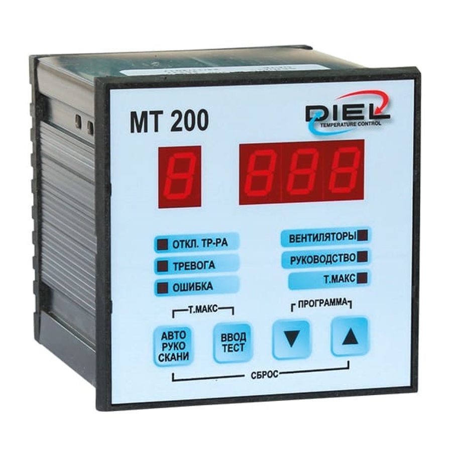
MT 200 E INFORMAZIONI DI SICUREZZA PRIMA DI INSTALLARE LA CENTRALINA CONSULTARE SCRUPOLOSAMENTE IL MANUALE DI INSTALLAZIONE ED I DATI TECNICI. TALE MANUALE È DESTINATO A PERSONALE TECNICO ADEGUATAMENTE FORMATO. FUNZIONAMENTO DELLA CENTRALINA La centralina MT200 E, fa parte della famiglia MT200, serve a monitorare le temperature del trasformatore / motore per mezzo di sonde PT100 a 3 fili su massimo 4 canali. - Page 5 Uscite • Quattro relè 250 VAC 10 A massimi (carico resistivo), 1 contatto pulito di scambio. • Porta comunicazione ETHERNET, protocollo MODBUS-TCP (MT 200 E) Caratteristiche • Contenitore in NORYL auto estinguente. • Grado di protezione pannello frontale in policarbonato: IP65 (IP66 a richiesta) •...
-
Page 6: Precauzioni
MT 200 E • Risoluzione 1° C. • Temperatura di lavoro centralina da -40 °C a +60 °C. • Umidità ambiente ammessa massima 90% non condensante. • Collegamenti elettrici su morsettiere estraibili polarizzate. • Possibilità di commutare manualmente i relè mediante il menù di test relè per simulare o controllare l’affidabilità... -
Page 7: Montaggio
MT 200 E MONTAGGIO Eseguire nel pannello un foro da 91X91 mm, fissare la centralina con i ganci in dotazione. ALIMENTAZIONE E COLLEGAMENTI ELETTRICI Morsetti 1-2-3: Sonda canale nr. 1, colori bianco-rosso-rosso. Morsetti 4-5-6: Sonda canale nr. 2, colori bianco-rosso-rosso. -
Page 8: Pannello Frontale
MT 200 E locale dove è situato il trasformatore. Morsetti 19-20-21: Relè ALARM, viene eccitato al superamento di un grado della soglia impostata. Morsetti 22-23-24: Relè PRE-AL, viene eccitato al superamento di un grado della soglia impostata. Morsetto Porta Ethernet connettore RJ45. -
Page 9: Tasti Di Navigazione
MT 200 E >> Paragrafo DIAGNOSTICA SONDE TERMOMETRICHE Segnala l’intervento dei ventilatori. Segnala che la visualizzazione della temperatura è in Auto modalità manuale, per vedere gli altri canali utilizzare i tasti Manual . Se spento il funzionamento è in modaità AUTO (default), il display segnala il canale più... -
Page 10: Reset Allarmi
MT 200 E della centralina. >> Paragrafo PROGRAMMAZIONE RESET ALLARMI: Consente il reset allarmi. >> Paragrafo RESET RESET DEFAULT: Consente il reset allarmi ed il ripristino delle impostazioni di fabbrica. >> Paragrafo RESET SET AUTO/MAN/SCAN Premere il pulsante per scegliere il funzionamento tra AUTOMATICO, MANUALE, SCANSIONE. -
Page 11: Funzione T. Max
MT 200 E MANUALE: Visualizza per un uno qualsiasi dei 4 canali. Premere per scorrere tra i canali. Il led MANUAL è acceso. SCANSIONE: Visualizza ciclicamente nel display le temperature di ogni rispettivo canale. Il led MANUAL lampeggia. FUNZIONE T. MAX Per accedere alla funziona T. -
Page 12: Programmazione
MT 200 E PROGRAMMAZIONE Premere contemporaneamente i tasti per qualche secondo per entrare nel menu PROGRAMMAZIONE, compare la scritta PRG, successivamente il parametro F nel primo display indicherà e la configurazione in uso (default 0). Scegliere la configurazione desiderata premendo i tasti UP/DOWN scegliendo tra: •... -
Page 13: Programmazione Avanzata
MT 200 E H: INTERVENTO VENTILATORI, default 100 (non richiesto per configurazione 0 e 2) C: PROTEZIONE CUSCINETTI VENT., default 0, C=0 non attivo, C=1 accensione vent. 1 volta al giorno 5 min., C=2 accensione vent. 1 volta a sett. 5 min. -
Page 14: Diagnostica Sonde Termometriche
MT 200 E Viene proposto il FAN1, di default abilitato, per disabilitare il controllo della ventilazione, impostare il valore del primo display a 0 con i tasti e premere confermare. L: SPEGNIMENTO VENTILATORI, default 90 (se FAN1 abilitato) H: INTERVENTO VENTILATORI, default... -
Page 15: Reset
MT 200 E RESET RESET ALLARMI: Premere contemporaneamente i tasti per resettare gli allarmi. RESET DEFAULT: Premere contemporaneamente i tasti per: Resettare gli allarmi Ripristinare le impostazioni di fabbrica (F=0, P=140, A=160, H=110, L=90, C=0) Indirizzo IP: 192.168.1.205 Subnet mask 255.255.255.0 Gateway: 192.168.1.1... - Page 16 - 16 -...
- Page 17 MT 200 E INDEX SAFETY INFORMATION CONTROL UNIT OPERATION ELECTRICAL CHARACTERISTICS PRECAUTIONS WARRANTY RULES ASSEMBLY POWER SUPPLY AND ELECTRICAL CONNECTIONS FRONT PANEL SET AUTO/MAN/SCAN T. MAX FUNCTION DISPLAY-RELAY TEST FUNCTION PROGRAMMING ADVANCED PROGRAMMING THERMOMETRIC PROBES DIAGNOSTICS RESET ETHERNET CONTROL UNIT VIEW (TAB 1)
-
Page 18: Safety Information
MT 200 E SAFETY INFORMATION BEFORE INSTALLING THE CONTROL UNIT, READ THE INSTALLATION MANUAL AND THE TECHNICAL SPECIFICATIONS CAREFULLY. THIS MANUAL IS INTENDED FOR TECHNICAL STAFF ADEQUATELY TRAINED. CONTROL UNIT OPERATION The MT200 E control unit, is part of the MT200 family, serves to monitor the transformer/motor temperatures by means of 3-wire PT100 probes on up to 4 channels.It is equipped with 4 relays, 1 for ventilation, 1 for signalling faults and... - Page 19 Outputs • Four 250 VAC 10 A maximum (resistive load) relays, 1 clean changeover contact. • ETHERNET communication port, MODBUS-TCP protocol (MT 200 E) Characteristics • Self-extinguishing NORYL container. • Front panel protection grade in polycarbonate: IP65 (IP66 on request) •...
-
Page 20: Precautions
MT 200 E • Maximum permissible ambient humidity 90% non-condensing. • Electrical connections on polarised removable terminal blocks. • Possibility to manually switch relays using the relay test menu to simulate or control contact reliability. • Technical manual in five languages (other languages on request). -
Page 21: Assembly
MT 200 E ASSEMBLY Make a 91X91 mm hole in the panel, fix the control unit with the supplied hooks. POWER SUPPLY AND ELECTRICAL CONNECTIONS Terminals 1-2-3: Channel probe no.1, white-red-red colour Terminals 4-5-6: Channel probe no.2, white-red-red colour Terminals 7-8-9: Channel probe no.3, white-red-red colour... -
Page 22: Front Panel
MT 200 E conditioning the room where the transformer is located Terminals 19-20-21: Relay ALARM is energised when a set threshold level is exceeded. Terminals 22-23-24: PRE-AL relay is energised when a set threshold level is exceeded. Terminal 25: Ethernet port RJ45... -
Page 23: Navigation Keys
MT 200 E It reports a probe fault. >> Paragraph THERMOMETRIC PROBES DIAGNOSTICS It signals the intervention of the fans. Auto Signals that the temperature display is in manual mode, to see the other channels use the keys .If switched... -
Page 24: Alarms Reset
MT 200 E PROGRAM: Enter the control unit programming function. >>Paragraph PROGRAMMING ALARMS RESET: It allows alarm reset. >>Pragraph RESET RESET DEFAULT: It allows alarms to be reset and factory settings restored. >> Paragraph RESET SET AUTO/MAN/SCAN Press the button to select the operation between AUTOMATIC, MANUAL, SCAN. -
Page 25: Max Function
MT 200 E control unit returns to the normal operating status. The MANUAL LED is off. MANUAL: It displays for any of the 4 channels. Press to scroll through the channels. The MANUAL LED is on. SCAN: It displays the temperatures of each respective channel cyclically. -
Page 26: Programming
MT 200 E test function at any time. PROGRAMMING Press simultaneously the keys for a few seconds to enter the PROGRAMMING menu, the message PRG appears, then parameter F in the first display will indicate and the configuration in use... -
Page 27: Advanced Programming
MT 200 E A: ALARM (CONTROL UNIT INTERVENTION), default 160 L: FANS SHUTDOWN, default 90 (not required for configuration 0 and 2) H: FANS IGNITION, default 100 (not required for configurations 0 and 2) C: PROTECTION OF FAN BEARINGS, default 1, C=0 not active, C=1 fan ignition... -
Page 28: Thermometric Probes Diagnostics
MT 200 E A: ALARM (Usually used for network release), default 160 FAN1 is proposed, as enabled default, to disable the ventilation control, set the value of the first display to 0 with the keys and press to confirm. L: FANS SHUTDOWN, default 90 (if FAN1... -
Page 29: Reset
MT 200 E with relative channel number and LED diode lighting. RESET RESET ALARMS: Simultaneously press the keys to reset the alarms. RESET DEFAULT: Simultaneously press the keys Reset the alarms Restore factory settings (P=140, A=160, H=110, L=90, C=1) IP address:192.168.1.205 Subnet mask 255.255.255.0... - Page 30 - 30 -...
- Page 31 MT 200 E INDEX INFORMATIONS DE SÉCURITÉ FONCTIONNEMENT DE LA CENTRALE CARACTÉRISTIQUES ÉLECTRIQUES PRÉCAUTIONS NORMES DE GARANTIE MONTAGE ALIMENTATION ET BRANCHEMENTS ÉLECTRIQUES PANNEAU AVANT SET AUTO/MAN/SCAN FONCTION T.MAX FONCTION TEST ÉCRAN-RELAIS PROGRAMMATION PROGRAMMATION AVANCÉE DIAGNOSTIC SONDES THERMOMÉTRIQUES RESET ETHERNET VUE DE L'UNITE DE CONTROLE (TAB 1)
-
Page 32: Informations De Sécurité
MT 200 E INFORMATIONS DE SÉCURITÉ AVANT D’INSTALLER LA CENTRALE, CONSULTER SCRUPULEUSEMENT LE MANUEL D’INSTALLATION ET LES DONNÉES TECHNIQUES. CE MANUEL EST DESTINÉ AU PERSONNEL TECHNIQUE DÛMENT FORMÉ. FONCTIONNEMENT DE LA CENTRALE La centrale T200 E, fait partie de la famille MT200, elle sert à contrôler les températures du transformateur / moteur au moyen de sondes PT100 à... - Page 33 Sorties • Quatre relais 250 VAC 10 A maximum (charge résistive), 1 contact propre d’échange. • Porte communication ETHERNET, protocole MODBUS-TCP (MT 200 E) Caractéristiques • Conteneur en NORYL auto extinguible. • Degré de protection panneau avant en polycarbonate: IP65 (IP66 sur demande) •...
-
Page 34: Précautions
MT 200 E • Température de travail centrale de -40 °C à +60 °C. • Humidité ambiante admise maximale 90% non condensante. • Branchements électriques sur borniers extractibles polarisés. • Possibilité de commuter manuellement les relais via le menu de test relais pour simuler ou pour contrôler la fiabilité... -
Page 35: Montage
MT 200 E MONTAGE Effectuer un trou de 91x91 mm dans le panneau puis fixer la centrale à l'aide des crochets en dotation. ALIMENTATION ET BRANCHEMENTS ÉLECTRIQUES Bornes 1-2-3: Sonde canal n. 1, couleurs blanc-rouge-rouge Bornes 4-5-6: Sonde canal n. 2, couleurs blanc-rouge-rouge Bornes 7-8-9: Sonde canal n. -
Page 36: Panneau Avant
MT 200 E ou bien pour le conditionnement du local où est situé le transformateur Bornes 19-20-21: Relais ALARM qui est excité au dépassement d’un degré par rapport au seuil configuré. Bornes 22-23-24: Relais PRE- AL qui est excité au dépassement d’un degré... -
Page 37: Touches De Navigation
MT 200 E >> Paragraphe DIAGNOSTIC SONDES THERMOMÉTRIQUES Signale l’intervention des ventilateurs. Signale que l’affichage de la température est en modalité Auto manuelle; pour voir les autres canaux, utiliser les touches Manual . Si éteint, le fonctionnement est en modalité... -
Page 38: Set Auto/Man/Scan
MT 200 E centrale. >> Paragraphe PROGRAMMATION RESET ALARMES: Permet la remise à zéro des alarmes. >> Paragraphe RESET RESET DEFAULT: Permet de remettre à zéro les alarmes et de rétablir les configurations d’usine. >> Paragraphe RESET SET AUTO/MAN/SCAN Appuyer... -
Page 39: Fonction T.max
MT 200 E fonctionnement. Le led MANUAL est éteint. MANUEL: Affiche un par un n’importe lequel des 4 canaux. Appuyer sur pour passer entre les canaux. Le led MANUAL est allumé. BALAYAGE: Affiche à l’écran les températures de chaque canal respectif de manière cyclique. -
Page 40: Programmation
MT 200 E premier relais PRE est proposé. Les touches permettent de commuter entre 0 et 1 pour exciter et désexciter le relais; une fois le test effectué, appuyer sur pour passer au relais successif; appuyer sur pour sortir à tout moment de la fonction de test. -
Page 41: Programmation Avancée
MT 200 E , à confirmer avec la touche P: PRÉ-ALARME, défaut 140 A: ALARME (INTERVENTION CENTRALE), défaut 160 L: EXTINCTION VENTILATEURS, défaut 90 (non requis pour configuration 0 et 2) H: INTERVENTION VENTILATEURS, défaut 100 (non requis pour configuration 0 et 2) C: PROTECTION ROULEMENTS VENTILATEURS, défaut 1, C=0 non actif,... - Page 42 MT 200 E Les valeurs suivantes sont ensuite proposées, modifiables à l'aide des touches , à confirmer avec la touche P: PRÉ-ALARME, défaut 140 A: ALARME (Utilisée normalement pour se déconnecter du réseau, défaut 160 Le FAN1 est proposé, de défaut activé; pour désactiver le contrôle de l’aération, configurer...
-
Page 43: Diagnostic Sondes Thermométriques
MT 200 E DIAGNOSTIC SONDES THERMOMÉTRIQUES SONDE INTERROMPUE: commutation du relais de FAULT, écran clignotant, affichage des lettres "ICF" avec numéro de canal correspondant et allumage led FAULT. SONDE EN COURT-CIRCUIT: commutation du relais de FAULT, écran clignotant, affichage des lettres "SCF"... - Page 44 - 44 -...
- Page 45 MT 200 E INDEX SICHERHEITSINFORMATIONEN BEDIENUNG DES STEUERGERÄTES ELEKTRISCHE EIGENSCHAFTEN VORSICHTSMASSNAHMEN GARANTIEBESTIMMUNGEN MONTAGE STROMVERSORGUNG UND ELEKTRISCHE ANSCHLÜSSE FRONTPLATTE SET AUTO/MAN/SCAN FUNKTION T.MAX DISPLAY-RELAIS-TESTFUNKTION PROGRAMMIERUNG ERWEITERTE PROGRAMMIERUNG DIAGNOSE DER TEMPERATURSONDEN RESET ETHERNET ANSICHT DER STEUEREINHEIT (TAB 1) MODBUS TCP/IP-REGISTER (TAB 2)
-
Page 46: Sicherheitsinformationen
MT 200 E SICHERHEITSINFORMATIONEN VOR DER INSTALLATION DES STEUERGERÄTS DIE INSTALLATIONSANLEITUNG UND DIE TECHNISCHEN DATEN LESEN. DIESES HANDBUCH IST FÜR TECHNISCHES PERSONAL BESTIMMT, DAS ENTSPRECHEND GESCHULT IST BEDIENUNG DES STEUERGERÄTES Das Steuergerät MT200 E aus der Familie MT200 dient zur Überwachung der Transformator- / Motortemperaturen durch 3-Leiter-PT100-Sonden auf bis zu 4 Kanälen. - Page 47 MT 200 E Ausgänge • Vier Relais 250 VAC 10 A maximal (ohmsche Last), 1 potentialfreier Wechselkontakt. • ETHERNET-Kommunikationsport, MODBUS-TCP-Protokoll (MT 200 E) Eigenschaften • Selbstlöschender NORYL-Behälter. • Schutzart der Frontplatte aus Polycarbonat: IP65 (IP66 auf Anfrage) • Schutzart der Rückseite auf der Klemmleistenseite: IP20 •...
-
Page 48: Vorsichtsmassnahmen
MT 200 E • Technisches Handbuch in fünf Sprachen (andere Sprachen auf Anfrage). • Konstruktion gemäß den Vorschriften • Eingangsfilter gegen Störungen gemäß den Vorschriften. • Tropisierung (optional). VORSICHTSMASSNAHMEN Führen Sie keine Durchschlagsfestigkeits- oder Teilentladungsprüfungen an elektrischen Maschinen mit eingesetztem Steuergerät durch. Vermeiden Sie nach Möglichkeit, das Steuergerät direkt an die Sekundärseite des zu... -
Page 49: Stromversorgung Und Elektrische Anschlüsse
MT 200 E STROMVERSORGUNG UND ELEKTRISCHE ANSCHLÜSSE Klemmen 1-2-3: Sonde Kanal Nr. 1, weiß-rot-rot Klemmen 4-5-6: Sonde Kanal Nr. 2, weiß-rot-rot Klemmen 7-8-9: Sonde Kanal Nr. 3, weiß-rot-rot Klemmen 10-11-12: Sonde Kanal Nr. 4, weiß-rot-rot Klemmen 13-14-15: Das FAULT- Relais ist normalerweise während des Betriebs des Steuergerätes... -
Page 50: Frontplatte
MT 200 E Klemmen 19-20-21: Das ALARM- Relais wird aktiviert, wenn ein festgelegter Schwellenwert überschritten wird. Klemmen 22-23-24: Das PRE-AL- Relais wird ausgelöst, wenn ein eingestellter Schwellenwert überschritten wird. Klemme 25: RJ45-Anschluss für Ethernet-Anschluss Klemmen AL1-GND-AL2 Steuergerät kann mit (24÷240) Volt AC/DC ±10% 50-60 Hz ohne Einhaltung... - Page 51 MT 200 E >> Abschnitt DIAGNOSE DER TEMPERATURSONDEN Zeigt an, dass die Lüfter eingegriffen haben. Zeigt an, dass sich die Temperaturanzeige im manuellen Auto Modus befindet, um die anderen Kanäle mit den Tasten anzuzeigen . Im ausgeschalteten Zustand befindet Manual sich der Betrieb im AUTO-Modus (Standardeinstellung), das Display zeigt den heißesten Kanal und die relative...
-
Page 52: Set Auto/Man/Scan
MT 200 E ALARME ZURÜCKSETZEN: Ermöglicht das Zurücksetzen der Alarme. >> Abschnitt RESET RESET DEFAULT: Ermöglicht das Zurücksetzen von Alarmen und das Wiederherstellen der Werkseinstellungen. >> Abschnitt RESET SET AUTO/MAN/SCAN Drücken Taste, zwischen AUTOMATISCH, MANUELL und ABTASTUNG zu wählen. AUTOMATISCH: Zeigt die höchste gefundene Temperatur und die entsprechende Kanalnummer an. -
Page 53: Funktion T.max
MT 200 E MANUELL: Ansicht für einen der 4 Kanäle. Drücken Sie um durch die Kanäle zu blättern. Die LED MANUELL ist eingeschaltet. ABTASTEN: Zeigt die Temperaturen des jeweiligen Kanals zyklisch im Display an. Die LED MANUELL blinkt. FUNKTION T.MAX Die Tasten müssen gleichzeitig gedrückt... -
Page 54: Programmierung
MT 200 E Tasten kann zwischen 0 und 1 geschaltet werden, um das Relais zu aktivieren und zu deaktivieren. Wenn der Test abgeschlossen ist, drücken Sie , um zum nächsten Relais zu wechseln, und drücken Sie , um die Testfunktion jederzeit zu beenden. -
Page 55: Erweiterte Programmierung
MT 200 E geändert werden, um mit der Taste bestätigt zu warden. P: VORALARM, Default 140 A: ALARM (EINGRIFF DES STEUERGERÄTES), Default 160 L: AUSSCHALTEN DER LÜFTER, Default 90 (nicht erforderlich für Konfiguration 0 und H: EINGRIFF DER LÜFTER, Default 100. - Page 56 MT 200 E Bestätigung. Die folgenden Werte werden dann vorgeschlagen und können mit den Tasten geändert werden, um mit der Taste bestätigt zu warden. P: VORALARM, Default 140 A: ALARM (wird normalerweise für die Netzwerkfreigabe verwendet), Default 160 FAN1 wird standardmäßig aktiviert, um die Lüftungssteuerung zu deaktivieren.
-
Page 57: Diagnose Der Temperatursonden
MT 200 E DIAGNOSE DER TEMPERATURSONDEN UNTERBROCHENE SONDE: FAULT-Relais- Umschaltung, blinkende Anzeige, Buchstaben "ICF" werden angezeigt mit relativer Kanalnummer und eingeschalteter FAULT-LED. KURZGESCHLOSSENE SONDE: FAULT-Relais- Umschaltung, blinkende Anzeige, Buchstaben "SCF" werden angezeigt relativer Kanalnummer und eingeschalteter LED-Diode. RESET ALARME ZURÜCKSETZEN: Drücken Sie gleichzeitig die Tasten , um die Alarme zurückzusetzen. - Page 58 MT 200 E ÍNDICE INFORMACIONES DE SEGURIDAD FUNCIONAMIENTO DE LA CENTRALITA CARACTERÍSTICAS ELÉCTRICAS PRECAUCIONES NORMAS DE GARANTÍA MONTAJE ALIMENTACIÓN Y CONEXIONES ELÉCTRICAS PANEL DELANTERO SET AUTO/MAN/SCAN FUNCIÓN T.MÁX FUNCIÓN PRUEBA VISUALIZADOR-RELÉ PROGRAMACIÓN PROGRAMACIÓN AVANZADA DIAGNÓSTICO DE SONDAS TERMOMÉTRICAS REINICIACIÓN ETHERNET...
-
Page 59: Informaciones De Seguridad
MT 200 E INFORMACIONES DE SEGURIDAD ANTES DE INSTALAR LA CENTRALITA CONSULTE ESCRUPLOSAMENTE EL MANUAL DE INSTALACIÓN Y LOS DATOS TÉCNICOS. DICHO MANUAL ESTÁ DESTINADO AL PERSONAL TÉCNICO ADECUADAMENTE FORMADO FUNCIONAMIENTO DE LA CENTRALITA La centralita MT200 E forma parte de la familia MT200, sirve para monitorizar las temperaturas del transformador / motor por medio de sondas PT100 de 3 alambres sobre un máximo de 4 canales. - Page 60 • Memorización permanente de los valores programados y de los datos alcanzados por cada canal (umbrales y máximos históricos). • Rigidez dieléctrica entre los contactos de los relés y línea de alimentación 2.5 KVAC de 60". - 60 -...
-
Page 61: Precauciones
• Filtro de ingreso contra los disturbios conforme con • Tropicalización opcional. PRECAUCIONES No efectúe pruebas de rigidez dieléctrica o de descargas parciales en las máquinas eléctricas con la centralita conectada, evite si es posible conectar directamente la centralita al secundario del transformador a proteger; puede suceder que sin protección, al cierre del interruptor a valle del transformador... -
Page 62: Montaje
MT 200 E MONTAJE Efectúe en el panel un agujero de 91X91 mm, fije la centralita con los ganchos en dotación. ALIMENTACIÓN Y CONEXIONES ELÉCTRICAS Bornes 1-2-3: Sonda canal n. 1, colores blanco-rojo-rojo Bornes 4-5-6: Sonda canal n. 2, colores blanco-rojo-rojo Bornes 7-8-9: Sonda canal n. -
Page 63: Panel Delantero
MT 200 E transformador para acondicionamiento del local donde está situado el transformador. Bornes 19-20-21: Relé ALARM, se excita cuando se supera de un grado el umbral planteado. Bornes 22-23-24: Relé PRE-AL, se excita cuando se supera de un grado el umbral planteado. - Page 64 MT 200 E Indica una avería en las sondas. >> Párrafo DIAGNÓSTICA DE LAS SONDAS TERMOMÉTRICAS Indica la intervención de los ventiladores. Indica que la visualización de la temperatura está en modo Auto manual, para ver los otros canales utilice las teclas Manual .
-
Page 65: Set Auto/Man/Scan
MT 200 E PROGRAM: Se entra en la función de programación de la centralita. >> Párrafo PROGRAMACIÓN REINICIO ALARMAS: Permite el reinicio de las alarmas. >> Párrafo REINICIO REINICIO POR DEFECTO: Permite el reinicio de la alarmas y el restablecimiento de los planteamientos de fábrica. -
Page 66: Función T.máx
MT 200 E funcionamiento normal. El led MANUAL está apagado. MANUAL: Visualiza cualquiera de los 4 canales. Pulse para desfilar por los canales. El led MANUAL está encendido. BARRIDO: Visualiza cíclicamente visualizador las temperaturas de cada respectivo canal. El led MANUAL está intermitente. -
Page 67: Programación
MT 200 E primer relé PRE. Con las teclas posible conmutar entre 0 y 1 para excitar y desexcitar el relé, con la prueba efectuada pulse para pasar al siguiente relé, pulse para salir en cualquier momento de la función de prueba. -
Page 68: Programación Avanzada
MT 200 E A: ALARMA (INTERVENCIÓN DE LA CENTRALITA), valor por defecto 160 L: APAGADO DE LOS VENTILADORES, valor por defecto 90 (no requerido para configuración 0 y 2) H: INTERVENCIÓN DE LOS VENTILADORES, valor por defecto 100 (no REQUERIDO PARA CONFIGURACIÓN 0 Y 2) C: PROTECCIÓN DE LOS COJINETES... -
Page 69: Diagnóstico De Sondas Termométricas
MT 200 E P: PREALARMA, valor por defecto 140 A: ALARMA, usada por lo general para el desenganche de la red, valor por defecto 160. Se propone el FAN1, de valor por defecto habilitado, para deshabilitar el control de la ventilación plantee en 0 el valor del primer... -
Page 70: Reiniciación
MT 200 E encendido del led FAULT. SONDA EN CORTOCIRCUITO: conmutación del relé FAULT, visualizador intermitente, visualización de las letras "SCF" con respectivo número de canal y encendido del diodo led. REINICIACIÓN REINICIACIÓN ALARMAS: Pulse simultáneamente las teclas para reiniciar las alarmas REINICIACIÓN POR DEFECTO: Pulse simultáneamente... - Page 71 MT 200 E TAB 1 VISIONE CENTRALINA (TAB 1) CONTROL UNIT VIEW (TAB 1) VUE DE L'UNITE DE CONTROLE (TAB 1) ANSICHT DER STEUEREINHEIT (TAB 1) VISTA DE LA CENTRALITA (TAB 1) - 71 -...
- Page 72 MT 200 E TAB 2 TYPE DATA RANGE READ ONLY Temperature channel 1 -1000 / +20000 READ ONLY Temperature channel 2 -1000 / +20000 READ ONLY Temperature channel 3 -1000 / +20000 READ ONLY Temperature channel 4 -1000 / +20000 READ ONLY Historical max temp.
- Page 73 MT 200 E TAB 2 • Register 9 Status fault channel CH1 to CH4: bit 0 to bit 3 Fault not active Fault active • Register 10 Status relay channel Fan (bit 3) Fault (bit 2) Pre-alarm (bit 1) Alarm (bit 0)
- Page 74 MT 200 E TAB 3 SERVER WEB (TAB 3) WEB SERVER (TAB 3) SERVEUR WEB (TAB 3) WEBSERVER (TAB 3) SERVIDOR WEB (T - 74 -...
- Page 75 - 75 -...
- Page 76 Diel S.r.l. Via A. Pizzocaro, 9 - 36075 Montecchio Maggiore (VI) ITALY Tel +39 0444 440977 - Fax +39 0444 448728 info@diel-ed.it - www.diel-ed.it...