
Manuels Connexes pour Balluff BTL6-U101-M Série


Sommaire des Matières pour Balluff BTL6-U101-M Série
- Page 1 BTL6-U101-M _ _ _ _ -A/B/Y/Z-S4 Betriebsanleitung deutsch english User’s guide français Notice d’utilisation italiano Manuale d’uso español Manual de instrucciones...
- Page 2 www.balluff.com...
- Page 3 BTL6-U101-M _ _ _ _ -A/B/Y/Z-S4 Betriebsanleitung deutsch...
- Page 4 www.balluff.com...
-
Page 5: Table Des Matières
6.6.1 Device Access Locks 6.6.2 Profile Characteristic 6.6.3 PD Input Descriptor 6.6.4 Application Specific Tag 6.6.5 Nullpunkt-Offset 6.6.6 Event Configuration 6.6.7 Temperature 6.6.8 IO Link Variant config 6.6.9 Output Charakteristic 6.6.10 Magnet Mode 6.6.11 PD In Mapping Diagnosedaten www.balluff.com deutsch... - Page 6 BTL6-U101-M _ _ _ _ -A/B/Y/Z-S4 Magnetostriktives Positionsmesssystem – Bauform Stab Technische Daten Genauigkeit Umgebungsbedingungen Spannungsversorgung (extern) IO-Link-Schnittstelle Maße, Gewichte Zubehör Positionsgeber Befestigungsmutter Steckverbinder Typenschlüssel Anhang 10.1 Umrechnung Längeneinheiten 10.2 Typenschild deutsch...
-
Page 7: Benutzerhinweise
Die Positionsgeber sind in unterschiedlichen IODD IO-Device-Description Bauformen lieferbar und deshalb gesondert zu bestellen. Process data (Prozessdaten) Process data variable (Prozessdatenvariable) Zulassungen und Kennzeichnungen UL-Zulassung File No. E227256 US-Patent 5 923 164 Das US-Patent wurde in Verbindung mit diesem Produkt erteilt. www.balluff.com deutsch... -
Page 8: Sicherheit
Einsatz im Industriebereich vorgese- Die verwendeten Warnhinweise enthalten verschiedene hen. Die einwandfreie Funktion gemäß den Angaben in Signalwörter und sind nach folgendem Schema aufgebaut: den technischen Daten wird nur mit original Balluff Zubehör SIGNALWORT zugesichert, die Verwendung anderer Komponenten bewirkt Haftungsausschluss. -
Page 9: Aufbau Und Funktion
4572 mm lieferbar. Anzahl Positionsgeber Dämpfungszone: Messtechnisch nicht nutzbarer Bereich Der Betrieb ist mit einem oder zwei Positionsgebern am Stabende, der überfahren werden darf. möglich, wobei die Anzahl fest eingestellt oder flexibel gehandhabt werden kann (siehe Magnet Mode auf Seite 18). www.balluff.com deutsch... -
Page 10: Einbau Und Anschluss
BTL6-U101-M _ _ _ _ -A/B/Y/Z-S4 Magnetostriktives Positionsmesssystem – Bauform Stab Einbau und Anschluss Einbauvarianten Einbau vorbereiten Einbauvariante: Für die Aufnahme des BTL und des Nichtmagnetisierbares Material Positionsgebers empfehlen wir nichtmagnetisierbares Material. nichtmagnetisierbares Material Waagerechte Montage: Bei waagerechter Montage mit Nennlängen >... -
Page 11: Btl Einbauen
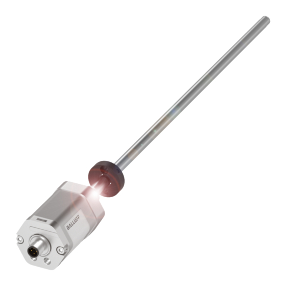
Möglich sind z. B. Torlon, Teflon oder Bronze. Gleitelement Positionsgeber Distanzring Bild 4-7: Fixierung Positionsgeber Ein Beispiel für den Einbau des BTL mit einem Stützrohr ist in Bild 4-8 auf Seite 10 dargestellt. Bild 4-5: Beispiel 1, BTL wird mit Gleitelement eingebaut www.balluff.com deutsch... -
Page 12: Elektrischer Anschluss
BTL6-U101-M _ _ _ _ -A/B/Y/Z-S4 Magnetostriktives Positionsmesssystem – Bauform Stab Einbau und Anschluss (Fortsetzung) Kabelverlegung Positionsgeber (z. B. BTL-P-1028-15R) Definierte Erdung! BTL und Schaltschrank müssen auf dem gleichen Erdungspotenzial liegen. Magnetfelder Das Positionsmesssystem ist ein magnetostriktives Sys- tem. Auf ausreichenden Abstand des BTL und des Aufnahme- zylinders zu starken externen Magnetfeldern achten. -
Page 13: Inbetriebnahme
Reparatur durch den Hersteller die korrekten Werte prüfen. Hinweise zum Betrieb – Funktion des BTL und aller damit verbundenen Kom- ponenten regelmäßig überprüfen. – Bei Funktionsstörungen das BTL außer Betrieb neh- men. – Anlage gegen unbefugte Benutzung sichern. www.balluff.com deutsch... -
Page 14: Io-Link-Schnittstelle
BTL6-U101-M _ _ _ _ -A/B/Y/Z-S4 Magnetostriktives Positionsmesssystem – Bauform Stab IO-Link-Schnittstelle Grundwissen IO-Link Parameter-Management In der Protokollversion 1.1 ist ein Parametermanager Allgemein definiert, der das Speichern von Device-Parametern auf IO-Link integriert konventionelle und intelligente Sensoren dem IO-Link-Master ermöglicht. Bei Austausch eines und Aktoren in Automatisierungssysteme und ist als IO-Link-Devices können die Parameterdaten des vorherin- Kommunikationsstandard unterhalb der klassischen Feld-... -
Page 15: Device-Spezifikation
Zykluszeit (Min Cycle Time) unterstützt, kann die Übertragungszeit wie folgt ermittelt werden: – Übertragungszeit BTL an 1.0 Master = Anzahl PD × minCycleTime (8 ms bei Standardvariante) – Übertragungszeit BTL an 1.1 Master = minCycleTime (1 ms bei Standardvariante) www.balluff.com deutsch... - Page 16 BTL6-U101-M _ _ _ _ -A/B/Y/Z-S4 Magnetostriktives Positionsmesssystem – Bauform Stab IO-Link Schnittstelle (Fortsetzung) Im Fehlerfall, d. h. wenn keine gültigen Daten ausgegeben Prozessdaten (PD) werden können, wird die jeweilige Prozessdatenvariable Die Varianten des BTL6-U10_-… geben über die IO-Link- durch den Fehlerwert 0x7FFFFFFC ersetzt. Die Daten Schnittstelle zyklisch ein oder mehrere Prozessdatenvaria- werden mithilfe des PD Invalid Bit nur dann als ungültig blen (PDV) mit einstellbarem Inhalt aus.
- Page 17 Read/Write Ja 0×00C9 (201 0, 1, 2 Magnet Mode (siehe Kap. 6.6.10) 2 Byte Read/Write Ja 0×00CA (202 0, 1…n PD In Mapping (siehe Kap. 6.6.11) n Bytes Read/Write Ja n entspricht Anzahl der Prozessdatenvariablen beim jeweiligen Typ. Tab. 6-5: Parameterdaten IO-Link-Schnittstelle www.balluff.com deutsch...
-
Page 18: Device Access Locks
BTL6-U101-M _ _ _ _ -A/B/Y/Z-S4 Magnetostriktives Positionsmesssystem – Bauform Stab IO-Link Schnittstelle (Fortsetzung) 6.6.1 Device Access Locks 6.6.4 Application Specific Tag Mit diesem Standardparameter ist es möglich, bestimmte Der Application Specific Tag bietet die Möglichkeit dem Funktionen des IO-Link-Devices zu aktivieren oder zu IO-Link-Device einen beliebigen, maximal 32 Byte großen deaktivieren. -
Page 19: Temperature
IO-Link-Variante wird der Compatibility Fehlermeldungen im übergeordneten System Mode zwischen den Einzelnen Varianten unterstützt (siehe müssen akzeptiert werden. Grundwissen IO-Link auf Seite 12). Der Parameter wird über die Funktion Factory Reset (siehe Kapitel 6.5) nicht auf Werkseinstel- lungen zurück gesetzt. www.balluff.com deutsch... -
Page 20: Output Charakteristic
BTL6-U101-M _ _ _ _ -A/B/Y/Z-S4 Magnetostriktives Positionsmesssystem – Bauform Stab IO-Link Schnittstelle (Fortsetzung) 6.6.9 Output Charakteristic Zugriff auf den Parameter Der Zugriff auf den Parameter ist wie folgt möglich: Dieser Parameter bestimmt die Ausgabefunktion des BTL – Subindex 0: Byte 1 = Diagnosezeit mit steigender oder fallender Kennlinie. -
Page 21: Diagnosedaten
0x8CA0 Warnung Magnet Number Change - temporary error state Die Anzahl der Positionsgeber im FMM Mode wurde geändert. Für die Dauer der eingestellten Diagnosezeit wird ein Fehler ausgegeben und die Prozess- daten als ungültig gekennzeichnet. Tab. 6-12: Diagnosedaten www.balluff.com deutsch... -
Page 22: Technische Daten
Für : Gebrauch in geschlossenen Räumen und bis zu einer Höhe von nach EN 60068-2-27 2000 m über Meeresspiegel. Vibration 12 g, 10…2000 Hz Einzelbestimmung nach Balluff Werknorm, Resonanzfrequenzen ausge- nach EN 60068-2-6 nommen Schutzart nach IEC 60529 IP67 Für : Das BTL muss extern über einen energiebegrenzten Stromkreis (in verschraubtem Zustand) gemäß... -
Page 23: Zubehör
Betriebstemperatur: – 40 °C…+ 60 °C BTL-P-1013-4S BTL-P-1028-15R (Sonderzubehör für Applikationen mit Stützrohranwendung): Gewicht: ca. 68 g Gehäuse: Aluminium 120° BTL-P-1012-4R Ø 4.3 Bild 8-2: Sonderzubehör BTL-P-1028-15R Befestigungsmutter BTL-P-1014-2R – Befestigungsmutter M18×1.5: BTL-A-FK01-E-M18×1.5 – Befestigungsmutter 3/4“-16UNF: BTL-A-FK01-E-3/4“-16UNF Bild 8-1: Einbaumaße Positionsgeber www.balluff.com deutsch... -
Page 24: Zubehör
BTL6-U101-M _ _ _ _ -A/B/Y/Z-S4 Magnetostriktives Positionsmesssystem – Bauform Stab Zubehör (Fortsetzung) Steckverbinder BTL (I) IO-Link-Master (II) L+ (18 30 V) … nicht belegt – L– (GND) Tab. 8-1: Pinbelegung IO-Link-Master Buchse gerade – Stecker gerade 44.0 48.5 M12x1 M12x1 Bild 8-3: Steckerverbinder gerade - gerade Bestellcode... -
Page 25: Typenschlüssel
A = metrisches Befestigungsgewinde M18x1.5, für Flachdichtung, Stabdurchmesser 10,2 mm B = metrisches Befestigungsgewinde M18x1.5, O-Ring, Stabdurchmesser 10,2 mm Y = Zollgewinde 3/4"-16UNF, für Flachdichtung, Stabdurchmesser 10,2 mm Z = Zollgewinde 3/4"-16UNF, O-Ring, Stabdurchmesser 10,2 mm Elektrischer Anschluss: S4 = 4-polig, M12-Stecker www.balluff.com deutsch... -
Page 26: Anhang
BTL6-U101-M _ _ _ _ -A/B/Y/Z-S4 Magnetostriktives Positionsmesssystem – Bauform Stab Anhang 10.1 Umrechnung Längeneinheiten 1 mm = 0,03937008 inch 1 inch = 25,4 mm inch inch 0,03937008 25,4 0,07874016 50,8 0,11811024 76,2 0,15748031 101,6 0,19685039 0,23622047 152,4 0,27559055 177,8 0,31496063 203,2 0,35433071 228,6 0,393700787 Tab. 10-1: Umrechnungstabelle mm-inch Tab. - Page 27 BTL6-U101-M _ _ _ _ -A/B/Y/Z-S4 User’s Guide english...
- Page 28 www.balluff.com...
- Page 29 6.6.1 Device Access Locks 6.6.2 Profile Characteristic 6.6.3 PD Input Descriptor 6.6.4 Application Specific Tag 6.6.5 Null point offset 6.6.6 Event Configuration 6.6.7 Temperature 6.6.8 IO Link Variant config 6.6.9 Output Characteristic 6.6.10 Magnet Mode 6.6.11 PD In Mapping Diagnostic data www.balluff.com english...
- Page 30 BTL6-U101-M _ _ _ _ -A/B/Y/Z-S4 Magnetostrictive Linear Position Sensor – Rod Style Technical data Accuracy Ambient conditions Supply voltage (external) IO-Link interface Dimensions, weights Accessories Magnets Mounting nut Connector Type code Appendix 10.1 Converting units of length 10.2 Part label english...
-
Page 31: Notes To The User
FMM Flexible Magnet Mode and must be ordered separately. IODD IO device description Process data Approvals and markings Process data variable UL approval File no. E227256 US Patent 5 923 164 The US patent was awarded in connection with this product. www.balluff.com english... -
Page 32: Safety
SIGNAL WORD using original Balluff accessories. Use of any other components will void the warranty. Hazard type and source Opening the BTL or non-approved use are not permitted... -
Page 33: Construction And Function
Damping zone: Area at the end of the rod that cannot be Operation is possible with one or two magnets, where the used for measurements, but which may be passed over. number can be fixed or flexible (see Magnet Mode on page 18). www.balluff.com english... -
Page 34: Installation And Connection
BTL6-U101-M _ _ _ _ -A/B/Y/Z-S4 Magnetostrictive Linear Position Sensor – Rod Style Installation and connection Installation guidelines Preparing for installation Installation note: We recommend using non- Non-magnetizable material magnetizable material to mount the BTL and magnet. Non-magnetizable material Horizontal assembly: For horizontal assembly with nominal lengths > 500 mm, support the rod and tighten it at the end if necessary. -
Page 35: Installing The Btl
Slide element Magnet Spacer ring Fig. 4-7: Fixing of magnet An example of how to install the BTL with a supporting rod is shown in Fig. 4-8 on page 10. Fig. 4-5: Example 1, BTL installed with slide element www.balluff.com english... -
Page 36: Electrical Connection
BTL6-U101-M _ _ _ _ -A/B/Y/Z-S4 Magnetostrictive Linear Position Sensor – Rod Style Installation and connection (continued) Cable routing Magnet (e.g. BTL-P-1028-15R) Defined ground! The BTL and the control cabinet must be at the same ground potential. Magnetic fields The position measuring system is a magnetostrictive system. -
Page 37: Startup
BTL or after repair by the manufacturer. Operating notes – Check the function of the BTL and all associated components on a regular basis. – Take the BTL out of operation whenever there is a malfunction. – Secure the system against unauthorized use. www.balluff.com english... -
Page 38: Io-Link Interface
BTL6-U101-M _ _ _ _ -A/B/Y/Z-S4 Magnetostrictive Linear Position Sensor – Rod Style IO-Link interface Basic knowledge about IO-Link Parameter management A parameter manager that enables device parameters to General be saved on the IO-Link master is defined in protocol IO-Link integrates conventional and intelligent sensors and version 1.1. -
Page 39: Device Specification
BTL, the transfer time can be determined as follows: – Transfer time, BTL to 1.0 Master = PD volume × minCycleTime (8 ms for standard variant) – Transfer time, BTL to 1.1 Master = minCycleTime (1 ms for standard variant) www.balluff.com english... -
Page 40: Process Data (Pd)
BTL6-U101-M _ _ _ _ -A/B/Y/Z-S4 Magnetostrictive Linear Position Sensor – Rod Style IO-Link interface (continued) In the event of an error, i.e. when no valid data can be Process data (PD) output, the respective process data variable is replaced The variants of the BTL6-U10_-…... - Page 41 2 bytes Read/Write Yes 0×00CA (202 0, 1 to n PD In Mapping (see sec. 6.6.11) n bytes Read/Write Yes n corresponds to the number of process data variables for the respective type. Tab. 6-5: Parameter data of IO-Link interface www.balluff.com english...
-
Page 42: Device Access Locks
BTL6-U101-M _ _ _ _ -A/B/Y/Z-S4 Magnetostrictive Linear Position Sensor – Rod Style IO-Link interface (continued) 6.6.1 Device Access Locks 6.6.4 Application Specific Tag With this standard parameter, it is possible to activate or The Application Specific Tag makes it possible to assign deactivate certain functions of the IO-Link device. -
Page 43: Temperature
Compatibility Mode is supported between the individual system must be accepted. variants (see Basic knowledge about IO-Link on The parameter is not reset to factory settings page 12). via the Factory Reset function (see section 6.5). www.balluff.com english... -
Page 44: Output Characteristic
BTL6-U101-M _ _ _ _ -A/B/Y/Z-S4 Magnetostrictive Linear Position Sensor – Rod Style IO-Link interface (continued) 6.6.9 Output Characteristic Access to the parameter Access to the parameter is possible as follows: This parameter determines the output function of the BTL –... -
Page 45: Diagnostic Data
Magnet Number Change - temporary error state The number of magnets was changed in FMM mode. For the duration of the set diagnostic time, an error is output and the process data is marked as invalid. Tab. 6-12: Diagnostic data www.balluff.com english... -
Page 46: Technical Data
: Use in enclosed spaces and up to a height of 2000 m above sea Shock rating 100 g/6 ms level. Continuous shock 50 g/2 ms Individual specifications as per Balluff factory standard, resonant per EN 60068-2-27 frequencies excluded Vibration 12 g, 10…2000 Hz : The BTL must be externally connected via a limited-energy per EN 60068-2-6 circuit as defined in UL 61010-1, a low-power source as defined in... -
Page 47: Accessories
BTL-P-1028-15R (special accessories for applications with a supporting rod): Weight: Approx. 68 g Housing: Aluminum 120° BTL-P-1012-4R Ø 4.3 Fig. 8-2: BTL-P-1028-15R special accessories BTL-P-1014-2R Mounting nut – M18×1.5 mounting nut: BTL-A-FK01-E-M18×1.5 – 3/4”-16UNF mounting nut: BTL-A-FK01-E-3/4”-16UNF Fig. 8-1: Magnet installation dimensions www.balluff.com english... -
Page 48: Connector
BTL6-U101-M _ _ _ _ -A/B/Y/Z-S4 Magnetostrictive Linear Position Sensor – Rod Style Accessories (continued) Connector BTL (I) IO-Link Master (II) L+ (18 30 V) … Not used – L– (GND) Tab. 8-1: IO-Link Master pin assignment Straight socket – straight plug 44.0 48.5 M12x1... -
Page 49: Type Code
A = Metric mounting thread M18x1.5, for flat seal, rod diameter 10.2 mm B = Metric mounting thread M18x1.5, O-ring, rod diameter 10.2 mm Y = 3/4”-16UNF thread, for flat seal, rod diameter 10.2 mm Z = 3/4"-16UNF thread, O-ring, rod diameter 10.2 mm Electrical connection: S4 = 4-pin, M12 plug www.balluff.com english... -
Page 50: Appendix
BTL6-U101-M _ _ _ _ -A/B/Y/Z-S4 Magnetostrictive Linear Position Sensor – Rod Style Appendix 10.1 Converting units of length 1 mm = 0.03937008 inches 1 inch = 25.4 mm inch inch 0.03937008 25.4 0.07874016 50.8 0.11811024 76.2 0.15748031 101.6 0.19685039 0.23622047 152.4 0.27559055 177.8 0.31496063 203.2 0.35433071 228.6 0.393700787 Tab. - Page 51 BTL6-U101-M _ _ _ _ -A/B/Y/Z-S4 Notice d’utilisation français...
- Page 52 www.balluff.com...
- Page 53 6.6.2 Profile Characteristic 6.6.3 PD Input Descriptor 6.6.4 Application Specific Tag 6.6.5 Offset point zéro 6.6.6 Event Configuration 6.6.7 Temperature 6.6.8 IO Link Variant config 6.6.9 Output Characteristic 6.6.10 Magnet Mode 6.6.11 PD In Mapping Données de diagnostic www.balluff.com français...
-
Page 54: Système De Mesure De Position Magnétostrictif - Modèle À Tige
BTL6-U101-M _ _ _ _ -A/B/Y/Z-S4 Système de mesure de position magnétostrictif – modèle à tige Caractéristiques techniques Précision Conditions ambiantes Alimentation électrique (externe) Interface IO-Link Dimensions, poids Accessoires Capteur de position Ecrous de fixation Connecteurs Code de type Annexe 10.1 Conversion unités de longueur 10.2 Plaque signalétique français... -
Page 55: Guide D'utilisation
FMM Flexible Magnet Mode Homologation UL IODD IO Device Description Dossier N° Process data (Donnees de processus) E227256 Process data variable (Variable de donnees de processus) Brevet US 5 923 164 Le brevet américain a été attribué en relation avec ce produit. www.balluff.com français... -
Page 56: Sécurité
Son bon fonctionnement, conformément aux MOT-CLE indications figurant dans les caractéristiques techniques, n'est garanti qu'avec les accessoires d'origine Balluff ; Type et source de danger l'utilisation d'autres composants entraîne la nullité de la garantie. -
Page 57: Structure Et Fonction
Le fonctionnement est possible avec un ou deux capteurs de mesure, située à l’extrémité de la tige, où le capteur de position. Il est à noter que ce nombre peut être réglé de peut toutefois pénétrer. manière fixe ou flexible (voir Magnet Mode, page 18). www.balluff.com français... -
Page 58: Montage Et Raccordement
BTL6-U101-M _ _ _ _ -A/B/Y/Z-S4 Système de mesure de position magnétostrictif – modèle à tige Montage et raccordement Variantes de montage Préparation du montage Variante de montage : pour la fixation du BTL et du Matériau non magnétisable capteur de position, nous recommandons l'utilisation de matériaux non magnétisable. -
Page 59: Montage Du Btl
Bague d’écartement Capteur de position Fig. 4-7 : Fixation du capteur de position Un exemple de montage du BTL avec support est représenté sur la Fig. 4-8, page 10. Fig. 4-5 : Exemple 1, BTL monté avec élément coulissant www.balluff.com français... -
Page 60: Raccordement Électrique
BTL6-U101-M _ _ _ _ -A/B/Y/Z-S4 Système de mesure de position magnétostrictif – modèle à tige Montage et raccordement (suite) Pose des câbles Capteur de position (p. ex. BTL-P-1028-15R) Mise à la terre définie ! Le BTL et l’armoire électrique doivent être reliés au même potentiel de mise à... -
Page 61: Mise En Service Du Système
BTL ou réparation par le fabricant. Conseils d’utilisation – Contrôler régulièrement le fonctionnement du BTL et de tous les composants associés. – En cas de dysfonctionnement, mettre le BTL hors service. – Protéger l’installation de toute utilisation non autorisée. www.balluff.com français... -
Page 62: Interface Io-Link
BTL6-U101-M _ _ _ _ -A/B/Y/Z-S4 Système de mesure de position magnétostrictif – modèle à tige Interface IO-Link Connaissances de base concernant IO-Link Gestion des paramètres Dans la version de protocole 1.1, un gestionnaire de Généralités paramètres permettant l’enregistrement des paramètres de IO-Link intègre des capteurs et actionneurs conventionnels l’appareil sur le maître IO-Link est défini. -
Page 63: Spécification De L'appareil
être déterminée comme suit : – Durée de transmission BTL sur maître 1.0 = nombre PD × Min Cycle Time (8 ms pour la version standard) – Durée de transmission BTL sur maître 1.1 = Min Cycle Time (1 ms pour la version standard) www.balluff.com français... -
Page 64: Données De Processus (Pd)
BTL6-U101-M _ _ _ _ -A/B/Y/Z-S4 Système de mesure de position magnétostrictif – modèle à tige Interface IO-Link (suite) En cas d’erreur, à savoir si aucune donnée valable ne peut Données de processus (PD) être émise, la variable de données de processus Les versions du BTL6-U10_-…... - Page 65 (voir chap. 6.6.10) 2 Bytes Read / Write Oui 0×00CA (202 0, 1…n PD In Mapping (voir chap. 6.6.11) n Bytes Read / Write Oui n correspond au nombre de variables de données de processus pour le type respectif. Tab. 6-5 : Données de paramètre pour interface IO-Link www.balluff.com français...
-
Page 66: Device Access Locks
BTL6-U101-M _ _ _ _ -A/B/Y/Z-S4 Système de mesure de position magnétostrictif – modèle à tige Interface IO-Link (suite) 6.6.1 Device Access Locks 6.6.4 Application Specific Tag Ce paramètre standard permet d’activer ou de désactiver Le paramètre Application Specific Tag offre la possibilité certaines fonctions de l’appareil IO-Link. -
Page 67: Io Link Variant Config
Compatibility Mode est reconnu parmi les différentes doivent être acceptés. variantes (voir Connaissances de base concernant IO-Link, Ce paramètre n’est pas réinitialisé via la fonction page 12). Factory Reset (voir chapitre 6.5) aux réglages d’usine. www.balluff.com français... -
Page 68: Output Characteristic
BTL6-U101-M _ _ _ _ -A/B/Y/Z-S4 Système de mesure de position magnétostrictif – modèle à tige Interface IO-Link (suite) 6.6.9 Output Characteristic Accès au paramètre L’accès au paramètre est possible comme suit : Ce paramètre détermine la fonction d’émission du BTL –... -
Page 69: Données De Diagnostic
Le nombre de capteurs de position a été modifié dans le mode FMM. Pour la durée du temps de diagnostic réglé, une erreur est émise et les données de processus sont marquées comme étant non valables. Tab. 6-12 : Données de diagnostic www.balluff.com français... -
Page 70: Caractéristiques Techniques
: utilisation à l’intérieur et jusqu’à une altitude max. de 2000 m Vibration 12 g, 10…2000 Hz au-dessus du niveau de la mer. selon EN 60068-2-6 Détermination individuelle selon la norme d’usine Balluff, exception faite Protection selon CEI 60529 IP67 des fréquences de résonance (à l’état vissé) Pour : le BTL doit être raccordé... -
Page 71: Accessoires
Boîtier : Aluminium 120° BTL-P-1012-4R Ø 4.3 Fig. 8-2 : Accessoire spécial BTL-P-1028-15R Ecrous de fixation BTL-P-1014-2R – Ecrou de fixation M18×1.5 : BTL-A-FK01-E-M18×1.5 – Ecrou de fixation 3/4"-16UNF : BTL-A-FK01-E-3/4"-16UNF Fig. 8-1 : Cotes de montage des capteurs de position www.balluff.com français... -
Page 72: Connecteurs
BTL6-U101-M _ _ _ _ -A/B/Y/Z-S4 Système de mesure de position magnétostrictif – modèle à tige Accessoires (suite) Connecteurs BTL (I) Maître IO-Link (II) L+ (18 30 V) … Non utilisé – L– (GND) Tab. 8-1 : Affectation des broches du maître IO-Link Douille droite –... -
Page 73: Code De Type
B = filetage de fixation métrique M18x1.5, joint torique, diamètre de tige 10,2 mm Y = filetage au pouce 3/4"-16UNF, pour joint plat, diamètre de tige 10,2 mm Z = filetage au pouce 3/4"-16UNF, joint torique, diamètre de tige 10,2 mm Raccordement électrique : S4 = 4 pôles, connecteur M12 www.balluff.com français... -
Page 74: Annexe
BTL6-U101-M _ _ _ _ -A/B/Y/Z-S4 Système de mesure de position magnétostrictif – modèle à tige Annexe 10.1 Conversion unités de longueur 1 mm = 0,03937008 pouce 1 pouce = 25,4 mm pouce pouce 0,03937008 25,4 0,07874016 50,8 0,11811024 76,2 0,15748031 101,6 0,19685039 0,23622047 152,4 0,27559055 177,8 0,31496063 203,2 0,35433071 228,6... - Page 75 BTL6-U101-M _ _ _ _ -A/B/Y/Z-S4 Manuale d’uso italiano...
- Page 76 www.balluff.com...
- Page 77 6.6.2 Profile Characteristic 6.6.3 PD Input Descriptor 6.6.4 Application Specific Tag 6.6.5 Offset punto zero 6.6.6 Event Configuration 6.6.7 Temperatura 6.6.8 IO Link Variant config 6.6.9 Output Characteristic 6.6.10 Magnet Mode 6.6.11 PD In Mapping Dati di diagnosi www.balluff.com italiano...
- Page 78 BTL6-U101-M _ _ _ _ -A/B/Y/Z-S4 Sensore di posizionamento lineare magnetostrittivo – versione a barra Dati tecnici Precisione Condizioni ambientali Tensione di alimentazione (esterna) Interfaccia IO-Link Dimensioni, pesi Accessori Datore di posizione Dado di fissaggio Connettori Legenda codici di identificazione Appendice 10.1 Conversione delle unità...
-
Page 79: Avvertenze Per L'utente
FMM Flexible Magnet Mode Autorizzazione UL IODD IO-Device-Description File No. Process data (Dati di processo) E227256 Process data variable (Variabile dati di processo) Brevetto statunitense 5 923 164 Il brevetto statunitense è stato rilasciato in relazione a questo prodotto. www.balluff.com italiano... -
Page 80: Uso Conforme
è garantito PAROLA DI SEGNALAZIONE soltanto con accessori originali Balluff, l’uso di altri componenti comporta l’esclusione della responsabilità. Natura e fonte del pericolo L’apertura o l’uso improprio del BTL non sono consentiti e Conseguenze in caso di mancato rispetto dell’avvertenza... -
Page 81: Struttura E Funzione
Zona di smorzamento: campo alla fine della barra non Il funzionamento è possibile con uno o due datori di utilizzabile a fini metrologici e che può essere oltrepassato. posizione; il numero può essere impostato in modo fisso o flessibile (vedere Magnet Mode a pagina 18). www.balluff.com italiano... -
Page 82: Montaggio E Collegamento
BTL6-U101-M _ _ _ _ -A/B/Y/Z-S4 Sensore di posizionamento lineare magnetostrittivo – versione a barra Montaggio e collegamento Varianti di montaggio Preparazione del montaggio Variante di montaggio: per l’installazione del BTL e del Materiale non magnetizzabile datore di posizione si consiglia l’impiego di materiale non magnetizzabile. -
Page 83: Montaggio Btl
Fig. 4-7: Fissaggio del datore di posizione Un esempio per il montaggio del BTL con un tubo di supporto è rappresentato nella Fig. 4-8 a pagina 10. Fig. 4-5: Esempio 1, il BTL viene montato con un elemento scorrevole www.balluff.com italiano... -
Page 84: Collegamento Elettrico
BTL6-U101-M _ _ _ _ -A/B/Y/Z-S4 Sensore di posizionamento lineare magnetostrittivo – versione a barra Montaggio e collegamento (continua) Posa dei cavi Datore di posizione (p. es. BTL-P-1028-15R) Messa a terra definita! Il BTL e l’armadio elettrico devono trovarsi sullo stesso potenziale di terra. Campi magnetici Il sensore di posizionamento lineare è... -
Page 85: Messa In Funzione Del Sistema
Avvertenze per il funzionamento – Controllare periodicamente il funzionamento del BTL e di tutti i componenti ad esso collegati. – In caso di anomalie di funzionamento disattivare il BTL. – Proteggere l’impianto da un uso non autorizzato. www.balluff.com italiano... -
Page 86: Interfacia Io-Link
BTL6-U101-M _ _ _ _ -A/B/Y/Z-S4 Sensore di posizionamento lineare magnetostrittivo – versione a barra Interfacia IO-Link Nozioni di base IO-Link Gestione dei parametri Nella versione protocollo 1.1 è definita una gestione Aspetti generali parametri che consente la memorizzazione di parametri IO-Link integra sensori e attuatori convenzionali e Device sul IO-Link Master. -
Page 87: Specifica Device
– Tempo di trasmissione BTL su master 1.0 = numero PD × minCycleTime (8 ms per variante standard) – Tempo di trasmissione BTL su master 1.1 = minCycleTime (1 ms per variante standard) www.balluff.com italiano... -
Page 88: Dati Identificazione
BTL6-U101-M _ _ _ _ -A/B/Y/Z-S4 Sensore di posizionamento lineare magnetostrittivo – versione a barra Interfaccia IO-Link (continua) In caso di errore, ovvero se non possono essere emessi Dati di processo (PD) dati validi, la relativa variabile dati di processo viene Le varianti di BTL6-U10_-…... -
Page 89: Dati Parametrici
Magnet Mode (Vedere Cap. 6.6.10) 2 byte Read/Write Sì 0×00CA (202 0, 1…n PD In Mapping (Vedere Cap. 6.6.11) n byte Read/Write Sì n corrisponde al numero di variabili dati di processo per il tipo relativo. Tab. 6-5: Dati parametrici interfaccia IO-Link www.balluff.com italiano... -
Page 90: Device Access Locks
BTL6-U101-M _ _ _ _ -A/B/Y/Z-S4 Sensore di posizionamento lineare magnetostrittivo – versione a barra Interfaccia IO-Link (continua) 6.6.1 Device Access Locks 6.6.4 Application Specific Tag Con questo parametro standard è possibile attivare o Application Specific Tag offre la possibilità di assegnare al disattivare determinate funzioni dell’IO-Link Device. -
Page 91: Io Link Variant Config
Compatibility Mode tra le singole varianti (vedere Nozioni di nel sistema sovraordinato. base IO-Link a pagina 12). Il parametro non viene ripristinato alle impostazioni di fabbrica tramite la funzione Factory Reset (vedere Cap. 6.5). www.balluff.com italiano... -
Page 92: Output Characteristic
BTL6-U101-M _ _ _ _ -A/B/Y/Z-S4 Sensore di posizionamento lineare magnetostrittivo – versione a barra Interfaccia IO-Link (continua) 6.6.9 Output Characteristic Accesso ai parametri L’accesso ai parametri è possibile come di seguito Questo parametro definisce la funzione di emissione del illustrato: BTL con linea caratteristica ascendente o discendente. -
Page 93: Dati Di Diagnosi
Il numero di datori di posizione in FMM Mode è stato modificato. Per la durata del tempo di diagnosi impostato viene emesso un errore e i dati di processo vengono contrassegnati come non validi. Tab. 6-12: Dati di diagnosi www.balluff.com italiano... -
Page 94: Dati Tecnici
: Uso in spazi chiusi e fino a un’altezza di 2000 m sul livello del secondo EN 60068-2-6 mare. Grado di protezione IP67 Rilevazione singola secondo la norma interna Balluff, frequenze di IEC 60529 risonanza escluse (connettore avvitato) : Il BTL deve essere collegato esternamente mediante un circuito elettrico ad energia limitata in base alla norma UL 61010-1 oppure... -
Page 95: Datore Di Posizione
Peso: ca. 68 g Supporto: alluminio 120° BTL-P-1012-4R Ø 4.3 Fig. 8-2: Accessori speciali BTL-P-1028-15R BTL-P-1014-2R Dado di fissaggio – Dado di fissaggio M18×1.5: BTL-A-FK01-E-M18×1.5 – Dado di fissaggio 3/4”-16UNF: BTL-A-FK01-E-3/4”-16UNF Fig. 8-1: Dimensioni montaggio datore di posizione www.balluff.com italiano... -
Page 96: Connettori
BTL6-U101-M _ _ _ _ -A/B/Y/Z-S4 Sensore di posizionamento lineare magnetostrittivo – versione a barra Accessori (continua) Connettori BTL (I) IO-Link Master (II) L+ (18 30 V) … Non utilizzato – L– (GND) Tab. 8-1: Occupazione pin IO-Link Master Presa diritta – connettore diritto 44.0 48.5 M12x1... -
Page 97: Legenda Codici Di Identificazione
B = filettatura di fissaggio metrica M18x1.5, O-ring, diametro barra 10,2 mm Y = filettatura in pollici 3/4”-16UNF, per guarnizione piatta, diametro barra 10,2 mm Z = filettatura in pollici 3/4”-16UNF, O-ring, diametro barra 10,2 mm Collegamento elettrico: S4 = connettore M12, a 4 poli www.balluff.com italiano... -
Page 98: Appendice
BTL6-U101-M _ _ _ _ -A/B/Y/Z-S4 Sensore di posizionamento lineare magnetostrittivo – versione a barra Appendice 10.1 Conversione delle unità di lunghezza 1 mm = 0,03937008 pollici 1 pollice = 25,4 mm pollici pollici 0,03937008 25,4 0,07874016 50,8 0,11811024 76,2 0,15748031 101,6 0,19685039 0,23622047 152,4 0,27559055 177,8 0,31496063 203,2 0,35433071 228,6... - Page 99 BTL6-U101-M _ _ _ _ -A/B/Y/Z-S4 Manual de instrucciones español...
- Page 100 www.balluff.com...
- Page 101 6.6.2 Profile Characteristic 6.6.3 PD Input Descriptor 6.6.4 Application Specific Tag 6.6.5 Offset de punto cero 6.6.6 Event Configuration 6.6.7 Temperature 6.6.8 IO Link Variant config 6.6.9 Output Characteristic 6.6.10 Magnet Mode 6.6.11 PD In Mapping Datos de diagnóstico www.balluff.com español...
- Page 102 BTL6-U101-M _ _ _ _ -A/B/Y/Z-S4 Sistema magnetostrictivo de medición de posición – Forma constructiva de varilla Datos técnicos Precisión Condiciones ambientales Alimentación de tensión (externa) Interfaz IO-Link Medidas, pesos Accesorios Sensor de posición Tuerca de fijación Conectores Código de modelo Anexo 10.1 Conversión de unidades de longitud 10.2 Placa de características...
-
Page 103: Indicaciones Para El Usuario
Homologaciones e identificaciones IODD IO Device Description Process data (Datos de proceso) Homologación UL File No. Process data variable (Variable de datos de E227256 proceso) Patente estadounidense 5 923 164 La patente estadounidense se ha concedido en relación con este producto. www.balluff.com español... -
Page 104: Uso Debido
óptimo según las indicaciones que figuran de señalización y se estructuran según el siguiente en los datos técnicos solo se garantiza con accesorios esquema: originales de Balluff; el uso de otros componentes provoca PALABRA DE SEÑALIZACIÓN la exoneración de responsabilidad. Tipo y fuente de peligro No se permite la apertura del BTL o un uso indebido. -
Page 105: Estructura Y Funcionamiento
Zona de amortiguación: zona no aprovechable desde el configurarse con flexibilidad (véase Magnet Mode en la punto de vista técnico de medición situada en el extremo página 18). de la varilla y que se puede sobrepasar. www.balluff.com español... -
Page 106: Montaje Y Conexión
BTL6-U101-M _ _ _ _ -A/B/Y/Z-S4 Sistema magnetostrictivo de medición de posición – Forma constructiva de varilla Montaje y conexión Variantes de montaje Preparación del montaje Variante de montaje: para alojar el BTL y el sensor de Material no imantable posición, recomendamos un material no imantable. -
Page 107: Montar El Btl
Fig. 4-7: Fijación del sensor de posición En la Fig. 4-8 de la página 10 se representa un ejemplo de montaje del BTL con un tubo de apoyo. Fig. 4-5: Ejemplo 1, el BTL se monta con un elemento de deslizamiento www.balluff.com español... -
Page 108: Conexión Eléctrica
BTL6-U101-M _ _ _ _ -A/B/Y/Z-S4 Sistema magnetostrictivo de medición de posición – Forma constructiva de varilla Montaje y conexión (continuación) Tendido de cables Sensor de posición (p. ej. BTL-P-1028-15R) Puesta a tierra definida El BTL y el armario eléctrico deben estar a idéntico potencial de puesta a tierra. -
Page 109: Puesta En Servicio
Indicaciones sobre el servicio – Compruebe periódicamente el funcionamiento del BTL y todos los componentes relacionados. – Si se producen fallos de funcionamiento, ponga fuera de servicio el BTL. – Asegure la instalación contra cualquier uso no autorizado. www.balluff.com español... -
Page 110: Interfaz Io-Link
BTL6-U101-M _ _ _ _ -A/B/Y/Z-S4 Sistema magnetostrictivo de medición de posición – Forma constructiva de varilla Interfaz IO-Link Aspectos básicos sobre IO-Link Gestión de parámetros En la versión de protocolo 1.1 está definido un gestor de Generalidades parámetros que permite memorizar los parámetros del El sistema IO-Link integra sensores y actuadores dispositivo en el maestro IO-Link. -
Page 111: Especificación De Dispositivo
– Tiempo de transferencia del BTL al maestro 1.0 = número de PD × minCycleTime (8 ms en la variante estándar) – Tiempo de transferencia del BTL al maestro 1.1 = minCycleTime (1 ms en la variante estándar) www.balluff.com español... -
Page 112: Datos De Identificación
BTL6-U101-M _ _ _ _ -A/B/Y/Z-S4 Sistema magnetostrictivo de medición de posición – Forma constructiva de varilla Interfaz IO-Link (continuación) En caso de error, es decir, cuando ya no pueden emitirse Datos de proceso (PD) datos válidos, el valor de error 0x7FFFFFFC sustituye a la Las variantes del BTL6-U10_-…... -
Page 113: System Command
(véase cap. 6.6.10) 2 bytes Read/Write Sí 0×00CA (202 0, 1…n PD In Mapping (véase cap. 6.6.11) n bytes Read/Write Sí n corresponde al número de variables de datos de proceso del tipo correspondiente. Tab. 6-5: Datos de parámetros de la interfaz IO-Link www.balluff.com español... - Page 114 BTL6-U101-M _ _ _ _ -A/B/Y/Z-S4 Sistema magnetostrictivo de medición de posición – Forma constructiva de varilla Interfaz IO-Link (continuación) 6.6.1 Device Access Locks 6.6.4 Application Specific Tag Con este parámetro estándar es posible activar o El parámetro Application Specific Tag permite asignar al desactivar determinadas funciones del dispositivo IO-Link.
- Page 115 (véase Aspectos básicos sobre correspondientes. IO-Link en la página 12). Con la función Factory Reset (véase capítulo 6.5), el parámetro no se repone a los ajustes de fábrica. www.balluff.com español...
- Page 116 BTL6-U101-M _ _ _ _ -A/B/Y/Z-S4 Sistema magnetostrictivo de medición de posición – Forma constructiva de varilla Interfaz IO-Link (continuación) 6.6.9 Output Characteristic Acceso al parámetro Es posible acceder al parámetro del siguiente modo: Este parámetro determina la función de salida del BTL con –...
-
Page 117: Datos De Diagnóstico
El número de sensores de posición en el FMM Mode se ha modificado. Durante el tiempo de diagnóstico ajustado se emite un error y los datos de proceso se identifican como no válidos. Tab. 6-12: Datos de diagnóstico www.balluff.com español... -
Page 118: Datos Técnicos
: uso en espacios cerrados y hasta una altura de 2000 m sobre Grado de protección según IP67 el nivel del mar. IEC 60529 (atornillado) Disposición individual según la norma de fábrica de Balluff, excluyendo frecuencias de resonancias. Para : el BTL se debe conectar externamente mediante un circuito Alimentación de tensión (externa) eléctrico con limitación de energía de conformidad con UL 61010-1, una... -
Page 119: Sensor De Posición
Aprox. 68 g Carcasa: Aluminio 120° BTL-P-1012-4R Ø 4.3 Fig. 8-2: Accesorios especiales BTL-P-1028-15R BTL-P-1014-2R Tuerca de fijación – Tuerca de fijación M18×1.5: BTL-A-FK01-E-M18×1.5 – Tuerca de fijación 3/4"-16UNF: BTL-A-FK01-E-3/4"-16UNF Fig. 8-1: Medidas de montaje de los sensores de posición www.balluff.com español... -
Page 120: Conectores
BTL6-U101-M _ _ _ _ -A/B/Y/Z-S4 Sistema magnetostrictivo de medición de posición – Forma constructiva de varilla Accesorios (continuación) Conectores BTL (I) Maestro IO-Link (II) L+ (18…30 V) no utilizado – L– (GND) Tab. 8-1: Asignación de pines del maestro IO-Link Casquillo recto –... -
Page 121: Código De Modelo
B = rosca de fijación métrica M18x1.5, junta tórica, diámetro de varilla 10,2 mm Y = rosca inglesa 3/4"-16UNF, para junta plana, diámetro de varilla 10,2 mm Z = rosca inglesa 3/4"-16UNF, junta tórica, diámetro de varilla 10,2 mm Conexión eléctrica: S4 = 4 polos, conector M12 www.balluff.com español... -
Page 122: Anexo
BTL6-U101-M _ _ _ _ -A/B/Y/Z-S4 Sistema magnetostrictivo de medición de posición – Forma constructiva de varilla Anexo 10.1 Conversión de unidades de longitud 1 mm = 0,03937008 pulgadas 1 pulgada = 25,4 mm pulgadas pulgadas 0,03937008 25,4 0,07874016 50,8 0,11811024 76,2 0,15748031 101,6 0,19685039 0,23622047 152,4 0,27559055 177,8 0,31496063 203,2... - Page 124 US Service Center CN Service Center Germany Germany China Balluff GmbH Balluff GmbH Balluff Inc. Balluff (Shanghai) trading Co., Ltd. Schurwaldstrasse 9 Schurwaldstrasse 9 8125 Holton Drive Room 1006, Pujian Rd. 145. 73765 Neuhausen a.d.F. 73765 Neuhausen a.d.F. Florence, KY 41042 Shanghai, 200127, P.R.