Télécharger Imprimer la page

Publicité

Les langues disponibles

Les langues disponibles

Liens rapides

Preface
Z97M-G43
H97M-G43
Motherboard
G52-79241X3

Publicité

loading

Sommaire des Matières pour MSI Z97M-G43

  • Page 1 Preface Z97M-G43 H97M-G43 Motherboard G52-79241X3...
  • Page 2 Copyright Notice The material in this document is the intellectual property of MICRO-STAR INTERNATIONAL. We take every care in the preparation of this document, but no guarantee is given as to the correctness of its contents. Our products are under continual improvement and we reserve the right to make changes without notice.
  • Page 3 If a problem arises with your system and no solution can be obtained from the user’s manual, please contact your place of purchase or local distributor. Alternatively, please try the following help resources for further guidance. Visit the MSI website for technical guide, BIOS updates, driver updates, and other information: http://www.msi.com/service/download/ Contact our technical staff at: http://register.msi.com/...
  • Page 4 Safety Instructions ■ Always read the safety instructions carefully. ■ Keep this User’s Manual for future reference. ■ Keep this equipment away from humidity. ■ Lay this equipment on a reliable flat surface before setting it up. ■ The openings on the enclosure are for air convection hence protects the equipment from overheating.
  • Page 5 FCC-B Radio Frequency Interference Statement This equipment has been tested and found to comply with the limits for a Class B digital device, pursuant to Part 15 of the FCC Rules. These limits are designed to provide reasonable protection against harmful interference in a residential installation. This equipment generates, uses and can radiate radio frequency energy and, if not installed and used in accordance with the instructions, may cause harmful interference to radio communications.
  • Page 6 Radiation Exposure Statement This equipment complies with FCC radiation exposure limits set forth for an uncontrolled environment. This equipment and its antenna should be installed and operated with minimum distance 20 cm between the radiator and your body. This equipment and its antenna must not be co-located or operating in conjunction with any other antenna or transmitter.
  • Page 7 Replace only with the same or equivalent type recommended by the manufacturer. Chemical Substances Information In compliance with chemical substances regulations, such as the EU REACH Regulation (Regulation EC No. 1907/2006 of the European Parliament and the Council), MSI provides the information of chemical substances in products at: http://www.msi.com/html/popup/csr/evmtprtt_pcm.html Preface...
  • Page 8 MSI will comply with the product take back requirements at the end of life of MSI-branded products that are sold into the EU. You can return these products to local collection points.
  • Page 9 MSI će poštovati zahtev o preuzimanju ovakvih proizvoda kojima je istekao vek trajanja, koji imaju MSI oznaku i koji su prodati u EU. Ove proizvode možete vratiti na lokalnim mestima za prikupljanje.
  • Page 10 MSI si adeguerà a tale Direttiva ritirando tutti i prodotti marchiati MSI che sono stati venduti all’interno dell’Unione Europea alla fine del loro ciclo di vita.
  • Page 11 CONTENTS ▍ English ...................... En-1 Motherboard Specifications ................En-2 Connectors Quick Guide ..................En-5 Back Panel Quick Guide ..................En-7 CPU (Central Processing Unit) ................En-9 Memory ......................En-13 Mounting Screw Holes ..................En-14 Power Supply ....................En-15 Expansion Slots ....................En-16 Video/ Graphics Cards ..................En-17 Internal Connectors ..................En-18 Jumpers ......................En-25 LED Status Indicators ..................En-26 Drivers and Utilities ..................En-27...
  • Page 12 Connecteurs internes ..................Fr-18 Cavaliers ......................Fr-25 Indicateurs d'état LED ..................Fr-26 Pilotes et Utilitaires ....................Fr-27 Configuration BIOS ...................Fr-28 Русский ....................Ru-1 Характеристики материнской платы .............. Ru-2 Краткое руководство по разъемам ..............Ru-5 Краткое руководство по работе с задней панелью ........Ru-7 ЦП (центральный процессор) ................. Ru-9 Память...
  • Page 13 English Thank you for choosing the Z97M-G43/ H97M-G43 Series (MS-7924 v1.X) Micro-ATX motherboard. The Z97M-G43/ H97M-G43 Series motherboards are based on Intel Z97/ H97 chipset for optimal system efficiency. Designed ® to fit the advanced Intel LGA1150 processor, the Z97M-G43/ H97M-G43 ®...
  • Page 14 - 6x USB 3.0 ports (4 ports on the back panel, 2 ports available through the internal USB connectors) - 8x USB 2.0 ports (2 ports on the back panel, 6 ports available through the internal USB connectors*) * Internal JUSB1 connector supports MSI Super Charger. Audio ■ Realtek ALC892 Codec ®...
  • Page 15 ■ CPU/System temperature detection ■ CPU/System fan speed detection Monitor ■ CPU/System fan speed control BIOS ■ 64 Mb flash (for Z97M-G43) ■ 128 Mb flash (for H97M-G43) Features ■ UEFI AMI BIOS ■ ACPI 5.0, PnP 1.0a, SM BIOS 2.7, DMI 2.0 ■...
  • Page 16 Software ■ Drivers ■ MSI - Command Center - Live Update 6 - Smart Utilities - Super Charger - Fast Boot - Network Genie - ECO Center ■ 7-ZIP ■ Intel Extreme Tuning Utility ■ Norton Internet Security Solution ■ Small Business Advantage (for H97M-G43) Form ■...
  • Page 17 Connectors Quick Guide DIMM3 CPU Socket DIMM2 DIMM4 JBAT1 DIMM1 CPUFAN JPWR2 SYSFAN2 Back Panel JPWR1 JUSB4 PCI_E1 M2_1 SATA5_6 PCI_E2 SATA3_4 PCI_E3 JTPM1 SATA1_2 PCI_E4 JCI1 JFP1 JFP2 JAUD1 JUSB2 JUSB1 JUSB3 JCOM1 SYSFAN1 JLPT1 En-5...
  • Page 18 Connectors Reference Guide Port Name Port Type Page Back Panel En-7 LGA1150 CPU Socket En-9 CPUFAN,SYSFAN1~2 Fan Power Connectors En-19 DIMM1~4 Memory Slots En-13 JAUD1 Front Panel Audio Connector En-23 JBAT1 Clear CMOS Jumper En-25 JCI1 Chassis Intrusion Connector En-22 JCOM1 Serial Port Connector En-24...
  • Page 19 Back Panel Quick Guide Optical PS/2 Keyboard/ S/PDIF-Out Mouse Combo VGA port LAN Port Port Line-In RS-Out HDMI Line-Out CS-Out SS-Out USB 2.0 Port DisplayPort USB 3.0 Port DVI-D port ▶ PS/2 Keyboard/Mouse Combo Port A combination of PS/2 mouse/keyboard DIN connector for a PS/2 mouse/keyboard.
  • Page 20 ® ▶ HDMI Port The High-Definition Multimedia Interface (HDMI) is an all-digital audio-video interface that is capable of transmitting uncompressed streams. HDMI supports all types of TV formats, including standard, enhanced, or high-definition video, plus multi-channel digital audio on a single cable. Important •...
  • Page 21 This motherboard is designed to support overclocking. Before attempting to overclock, please make sure that all other system components can tolerate overclocking. Any attempt to operate beyond product specifications is not recommend. MSI does not guarantee the damages or risks caused by inadequate operation beyond product specifications.
  • Page 22 CPU & Heatsink Installation When installing a CPU, always remember to install a CPU heatsink. A CPU heatsink is necessary to prevent overheating and maintain system stability. Follow the steps below to ensure correct CPU and heatsink installation. Wrong installation can damage both the CPU and the motherboard.
  • Page 23 3. Align the notches with the socket alignment keys. Lower the CPU straight down, without tilting or sliding the CPU in the socket. Inspect the CPU to check if it is properly seated in the socket. 4. Close and slide the load plate under the retention knob. Close and engage the load lever.
  • Page 24 7. Locate the CPU fan connector on the motherboard. 8. Place the heatsink on the motherboard with the fan’s cable facing towards the fan connector and the fasteners matching the holes on the motherboard. CPU fan connector 9. Push down the heatsink until the four fasteners get wedged into the holes on the motherboard.
  • Page 25 Memory These DIMM slots are used for installing memory modules. DIMM1 DIMM2 DIMM3 DIMM4 Video Demonstration Watch the video to learn how to install memories at the address below. http://youtu.be/76yLtJaKlCQ Dual-Channel mode Population Rule In Dual-Channel mode, the memory modules can transmit and receive data with two data bus channels simultaneously.
  • Page 26 Mounting Screw Holes When installing the motherboard, first install the necessary mounting stands required for an motherboard on the mounting plate in your computer case. If there is an I/O back plate that came with the computer case, please replace it with the I/O backplate that came with the motherboard package.
  • Page 27 Power Supply Video Demonstration Watch the video to learn how to install power supply connectors. http://youtu.be/gkDYyR_83I4 JPWR1~2: ATX Power Connectors These connectors allow you to connect an ATX power supply. To connect the ATX power supply, align the power supply cable with the connector and firmly press the cable into the connector.
  • Page 28 Expansion Slots This motherboard contains numerous slots for expansion cards, such as discrete graphics or audio cards. PCI_E1~4: PCIe Expansion Slots The PCIe slot supports the PCIe interface expansion card. PCIe 3.0 x16 Slot PCIe 2.0 x4 Slot PCIe 2.0 x1 Slot Important •...
  • Page 29 Adding on one or more discrete video cards will significantly boost the system’s graphics performance. For best compatibility, MSI graphics cards are recommended. Video Demonstration Watch the video to learn how to install a graphics card on PCIe x16 slot with butterfly lock.
  • Page 30 Internal Connectors SATA1~6: SATA Connectors This connector is a high-speed SATA interface port. Each connector can connect to one SATA device. SATA devices include disk drives (HDD), solid state drives (SSD), and optical drives (CD/ DVD/ Blu-Ray). Video Demonstration Watch the video to learn how to Install SATA HDD. http://youtu.be/RZsMpqxythc SATA6 SATA5...
  • Page 31 CPUFAN,SYSFAN1~2: Fan Power Connectors The fan power connectors support system cooling fans with +12V. If the motherboard has a System Hardware Monitor chipset on-board, you must use a specially designed fan with a speed sensor to take advantage of the CPU fan control. Remember to connect all system fans.
  • Page 32 JFP1, JFP2: System Panel Connectors These connectors connect to the front panel switches and LEDs. The JFP1 connector is compliant with the Intel Front Panel I/O Connectivity Design Guide. When ® installing the front panel connectors, please use the optional M-Connector to simplify installation.
  • Page 33 • Please only connect one device per USB port to ensure stable charging. • Super-Charger Technology is only available on select MSI motherboard models. Please refer to the MSI website to check if your motherboard has Super-Charger technology. • For iPad, JUSB1 (red mark) can still charge iPad in S3, S4, S5 state.
  • Page 34 JUSB4: USB 3.0 Expansion Connector The USB 3.0 port is backwards compatible with USB 2.0 devices. It supports data transfer rates up to 5Gbits/s (SuperSpeed). Important • Note that the VCC and GND pins must be connected correctly to avoid possible damage.
  • Page 35 JAUD1: Front Panel Audio Connector This connector allows you to connect the front audio panel located on your computer case. This connector is compliant with the Intel Front Panel I/O Connectivity Design ® Guide. M2_1: M.2 Port The M.2 port supports either M.2 SATA 6Gb/s module or M.2 PCIe module. Important •...
  • Page 36 JTPM1: TPM Module Connector This connector connects to a TPM (Trusted Platform Module). Please refer to the TPM security platform manual for more details and usages. JLPT1: Parallel Port Connector This connector is used to connect an optional parallel port bracket. The parallel port is a standard printer port that supports Enhanced Parallel Port (EPP) and Extended Capabilities Parallel Port (ECP) mode.
  • Page 37 Jumpers JBAT1: Clear CMOS Jumper There is CMOS RAM onboard that is external powered from a battery located on the motherboard to save system configuration data. With the CMOS RAM, the system can automatically boot into the operating system (OS) every time it is turned on. If you want to clear the system configuration, set the jumpers to clear the CMOS RAM.
  • Page 38 LED Status Indicators MSI LED LED Status Table The following table describes the status of LED indicators. LED Status Description Debug En-26...
  • Page 39 After you install the operating system you will need to install drivers to maximize the performance of the new computer you just built. MSI motherboard comes with a Driver Disc. Drivers allow the computer to utilize your motherboard more efficiently and take advantage of any special features we provide.
  • Page 40 "MSI Fast Boot" utility screen. Important • Please be sure to install the “MSI Fast Boot” utility before using it to enter the BIOS setup. • The items under each BIOS category described in this chapter are under continuous update for better system performance. Therefore, the description may be slightly different from the latest BIOS and should be held for reference only.
  • Page 41 Overview After entering BIOS, the following screen is displayed. Temperature monitor My Favorites Language System information Boot device priority bar Virtual OC Genie Button BIOS menu BIOS menu selection selection Menu display ▶ BIOS menu selection The following options are available: ■...
  • Page 42 Enables or disables the OC Genie function by clicking on this button. When enabled, this button will be light. Enabling OC Genie function can automatically overclock with MSI optimized overclocking profile. Important We recommend that you do not to make any modification in OC menu mode and do not to load defaults after enabling the OC Genie function.
  • Page 43 Operation You can control BIOS settings with the mouse and the keyboard. The following table lists and describes the hot keys and the mouse operations. Hot key Mouse Description <↑↓→← > Select Item Move the cursor <Enter> Select Icon/ Field Click/ Double-click the left button <Esc>...
  • Page 44 OC Menu This menu is for advanced users who want to overclock the mainboard. Important • Overclocking your PC manually is only recommended for advanced users. • Overclocking is not guaranteed, and if done improperly, can void your warranty or severely damage your hardware.
  • Page 45 ▶ Intel Turbo Boost [Enabled]* Enables or disables the Intel Turbo Boost. This item appears when the installed CPU ® supports this function. [Enabled] Enables this function to boost CPU performance automatically above rated specifications when system request the highest performance state.
  • Page 46 ▶ DRAM Timing Mode [Auto] Selects the memory timing mode. [Auto] DRAM timings will be determined based on SPD (Serial Presence Detect) of installed memory modules. [Link] Allows user to configure the DRAM timing manually for all memory channel. [UnLink] Allows user to configure the DRAM timing manually for respective memory channel.
  • Page 47 ▶ CPU Core/Ring/GT Voltage Mode [Auto]* Selects the control mode for CPU Core/ Ring/ GT voltages. [Auto] This setting will be configured automatically by BIOS. [Adaptive Mode] Sets the adaptive voltage automatically for optimizing the system performance. [Override Mode] Allows you to set the voltage manually. [Offset Mode] Allows you to set the offset voltage and select the voltage offset mode.
  • Page 48 ▶ Hyper-Threading Technology [Enabled] The processor uses Hyper-Threading technology to increase transaction rates and reduces end-user response times. Intel Hyper-Threading technology treats the multi cores inside the processor as multi logical processors that can execute instructions simultaneously. In this way, the system performance is highly improved.
  • Page 49 ▶ Intel Adaptive Thermal Monitor [Enabled] Enables or disables the Intel adaptive thermal monitor function to protect the CPU from overheating. [Enabled] Throttles down the CPU core clock speed when the CPU is over the adaptive temperature. [Disabled] Disables this function. ▶...
  • Page 50 ▶ Long Duration Power Limit (W) [Auto] Sets the long duration TDP power limit for CPU in Turbo Boost mode. ▶ Long Duration Maintained (s) [Auto] Sets the maintaining time for "Long duration power Limit(W)". ▶ Short Duration Power Limit (W) [Auto] Sets the short duration TDP power limit for CPU in Turbo Boost mode.
  • Page 51 Deutsch Danke, dass Sie das Z97M-G43/ H97M-G43 (MS-7924 v1.X) Micro-ATX Motherboard gewählt haben. Diese Z97M-G43/ H97M-G43 Motherboard basiert auf dem Intel Z97/ H97 Chipsatz und ermöglicht so ein optimales ® und effizientes System. Entworfen, um den hochentwickelten Intel ® LGA1150 Prozessor zu unterstützen, stellt die Z97M-G43/ H97M-G43 Motherboard die ideale Lösung zum Aufbau eines professionellen...
  • Page 52 Z97/ H97 Express Chipsatz ® Speicher ■ 4x DDR3 Speicherplätze unterstützen bis zu 32GB ■ Z97M-G43 unterstützt DDR3 3200(OC)/3100(OC)/ 3000(OC)/ 2800(OC)/ 2666(OC)/ 2600(OC)/ 2400(OC)/ 2200(OC)/ 2133(OC)/ 2000(OC)/ 1866(OC)/ 1600/ 1333/ 1066 MHz ■ H97M-G43 unterstützt DDR3 1600/ 1333/ 1066 MHz ■...
  • Page 53 Anschlussleiste, 2 Anschlüsse stehen durch die internen USB Anschlüsse zur Verfügung) - 8x USB 2.0 Anschlüsse (2 Anschlüsse an der rückseitigen Anschlussleiste, 6 Anschlüsse stehen durch die internen USB Anschlüsse zur Verfügung*) * Interner JUSB1 Anschluss unterstützt MSI Super Charger. Audio ■ Realtek ALC892 Codec ®...
  • Page 54 ■ GO2BIOS ■ Total Lüftersteuerung ■ Super Charger ■ SMART-Funktion ■ Kommandozentrale ■ ECO Center Software ■ Treiber ■ MSI - Kommandozentrale - Live Update 6 - SMART-Funktion - Super Charger - Fast Boot - Network Genie - ECO Center ■...
  • Page 55 Anschlussübersicht DIMM3 CPU Sockel DIMM2 DIMM4 JBAT1 DIMM1 CPUFAN JPWR2 SYSFAN2 Rück- tafel JPWR1 JUSB4 PCI_E1 M2_1 SATA5_6 PCI_E2 SATA3_4 PCI_E3 JTPM1 SATA1_2 PCI_E4 JCI1 JFP1 JFP2 JAUD1 JUSB2 JUSB1 JUSB3 JCOM1 SYSFAN1 JLPT1 De-5...
  • Page 56 Übersicht der Motherboard-Anschlüsse Port-Name Port-Typ Seite Rücktafel De-7 LGA1150 CPU Sockel De-9 CPUFAN,SYSFAN1~2 Stromanschlüsse für Lüfter De-19 DIMM1~4 Speichersteckplätze De-13 JAUD1 Audioanschluss des Frontpanels De-23 JBAT1 Steckbrücke zur CMOS-Löschung De-25 JCI1 Gehäusekontaktanschluss De-22 JCOM1 Serieller Anschluss De-24 JFP1, JFP2 Systemtafelanschlüsse De-20 JLPT1 Parallele Schnittstelle...
  • Page 57 Rücktafel-Übersicht Optischer S/PDIF- PS/2 Tastatur/ Ausgang Maus Combo VGA Anschluss Anschluss Anschluss Line-In RS-Out HDMI Line-Out CS-Out SS-Out USB 2.0 DisplayPort USB 3.0 Anschluss DVI-D Anschluss Anschluss ▶ PS/2 Tastatur/Maus Combo Anschluss Die Kombination von PS/2 Maus/Tastatur Stecker DIN ist für eine PS/2 Maus/ ®...
  • Page 58 ▶ DisplayPort Der DisplayPort ist eine neue digitale StandardSchnittstelle. Dieser Anschluss wird zur Verbindung des Monitor mit DisplayPort-Eingang verwendet. ® ▶ HDMI Anschluss Das High-Definition Multimedia Interface (kurz HDMI) ist eine Schnittstelle für die volldigitale Übertragung von dekomprimierten Audio- und Video-Daten. Dieser HDMI unterstützt alle Formate für Fernsehen, einschließlich Standard- und Enhanced- oder HD-Video sowie das Audioformate der Unterhaltungselektronik.
  • Page 59 CPU (Prozessor) Erklärung zur LGA 1150 CPU Die Obserseite der LGA 1150 CPU hat zwei Justierungen und ein gelbes Dreieck um die korrekte Ausrichtung der CPU auf dem Motherboard zu gewährleisten. Das gelbe Dreieck des Prozessors definiert die Position des ersten Pins. Kerbe Kerbe Das goldene Dreieck des Prozessors...
  • Page 60 CPU & Kühlkörper Einbau Wenn Sie die CPU einbauen, denken sie bitte daran einen CPU-Kühler zu installieren. Ein CPU-Kühlkörper ist notwendig, um eine Überhitzung zu vermeiden und die Systemstabilität beizubehalten. Befolgen Sie die nachstehenden Schritte, um die richtige CPU und CPU-Kühlkörper Installation zu gewährleisten. Ein fehlerhafter Einbau führt zu Schäden an der CPU und dem Motherboard.
  • Page 61 3. Positionieren Sie die Kerben mit die Justiermarkierungen des Sockels. Setzen Sie die CPU nach unten, ohne Kippen oder Schieben der CPU im Sockel. Begutachten Sie, ob die CPU richtig im Sockel sitzt. 4. Schließen Sie und schieben Sie die Abdeckplatte unter dem Rückhalteknopf. Verschließen Sie den Verschlusshebel.
  • Page 62 7. Machen Sie den CPU-Lüfteranschluss auf dem Motherboard ausfinding. 8. Setzen Sie den Kühlkörper auf die CPU und beachten Sie die Übereinstimmung der Lüfterverankerungen mit den dafür vorgsehenen Löchern auf der Motherboard -Platine. CPU-Lüfteranschluss 9. Drücken Sie nach der korrekten Positionierung des Kühlkörpers die Arretierungsstifte mit leichtem Druck nach unten bis sie einrasten.
  • Page 63 Speicher Die DIMM-Steckplätze nehmen Arbeitsspeichermodule auf. DIMM1 DIMM2 DIMM3 DIMM4 Video-Demonstration Anhand dieses Video an untenstehender Adresse erfahren Sie, wie Sie die Speichermodule installieren. http://youtu.be/76yLtJaKlCQ Populationsregeln für Dual-Kanal-Speicher Im Dual-Kanal-Modus können Arbeitsspeichermodule Daten über zwei Datenbusleitungen gleichzeitig senden und empfangen. Durch Aktivierung des Dual- Kanal-Modus wird die Leistung Ihres Systems verbessert.
  • Page 64 Schraubenlöcher für die Montage Verwenden Sie die dem Motherboard beiliegende I/O-Platte und setzen Sie sie mit leichtem Druck von innen in die Aussparung des Computergehäuses ein. Zur Installation des Motherboards in Ihrem PC-Gehäuse befestigen Sie zunächst die dem Gehäuse beiliegenden Abstandhalter im Gehäuse. Legen Sie das Motherboard mit den Schraubenöffnungen über den Abstandhaltern und schrauben Sie das Motherboard mit den dem Gehäuse beiliegenden Schrauben fest.
  • Page 65 Stromversorgung Video-Demonstration Anhand dieses Video an untenstehender Adresse erfahren Sie, wie Sie die Stromversorgungsstecker installieren. http://youtu.be/gkDYyR_83I4 JPWR1~2: ATX Stromanschlüsse Mit diesem Anschluss verbinden Sie den ATX Stromanschlusse. Achten Sie bei dem Verbinden des ATX Stromanschlusses darauf, dass der Anschluss des Netzteils richtig auf den Anschluss an der Hauptplatine ausgerichtet ist.
  • Page 66 Erweiterungssteckplätze Dieses Motherboard enthält zahlreiche Schnittstellen für Erweiterungskarten, wie diskrete Grafik-oder Soundkarten. PCI_E1~4: PCIe Erweiterungssteckplätze Der PCIe Steckplatz unterstützt PCIe-Erweiterungskarten. PCIe 3.0 x16-Steckplatz PCIe 2.0 x4-Steckplatz PCIe 2.0 x1-Steckplatz Wichtig • Die zwei PCIe x1 Steckplätze können nicht gleichzeitig genutzt werden. Wenn Sie eine Erweiterungskarte in einem der beiden PCIe 2.0 x1 Steckplätze installieren, steht der andere Steckplatz nicht mehr zur Verfügung.
  • Page 67 Video/ Grafikkarten Fall im Prozessor integriert, nutzt dieses Motherboard den im Prozessor befindlichen Grafikprozessor. Zusätzliche Grafikkarten können aber über die auf dem Motherboard verfügbaren Erweiterungssteckplätze eingesetzt werden um die Systemleistung zu erhöhen. Video-Demonstration Anhand dieses Video an untenstehender Adresse erfahren Sie, wie Sie eine Grafikkarte im PCIe x16 Steckplatz mit Butterfly-Verschlüssen installieren.
  • Page 68 Interne Anschlüsse SATA1~6: SATA Anschlüsse Dieser Anschluss basiert auf der Hochgeschwindigkeitsschnittstelle Serial ATA (SATA). Pro Anschluss kann ein Serial ATA Gerät angeschlossen werden. Zu Serial ATA Geräten gehören Festplatten (HDD), SSD Festplatten (SSD) und optische Laufwerke (CD-/DVD-/Blu-Ray-Laufwerke). Video-Demonstration Anhand dieses Video an untenstehender Adresse erfahren Sie, wie Sie eine SATA-Featplatte installieren.
  • Page 69 CPUFAN,SYSFAN1~2: Stromanschlüsse für Lüfter Die Anschlüsse unterstützen aktive Systemlüfter mit +12V. Ist Ihr Motherboard mit einem Chipsatz zur Überwachung der Systemhardware versehen, dann brauchen Sie einen speziellen Lüfter mit Geschwindigkeitsregelung, um die Vorteile der Steuerung des CPU Lüfters zu nutzen. Vergessen Sie nicht, alle Systemlüftern anzuschließen. Einige Systemlüfter können nicht direkt an dem Motherboard angeschlossen werden und müssen stattdessen mit dem Netzteil direkt verbunden werden.
  • Page 70 JFP1, JFP2: Systemtafelanschlüsse Diese Anschlüsse sind für das Frontpanel angelegt. Sie dienen zum Anschluss der Schalter und LEDs des Frontpanels. JFP1 erfüllt die Anforderungen des “Intel Front ® Panel I/O Connectivity Design Guide”. Bei der Installation des Frontpanel-Anschlüsse, nutzen Sie bitte die optionalen M-Connectors um die Installation zu vereinfachen. Schließen Sie alle Kabel aus dem PC-Gehäuse zunächst an die M-Connectors an und stecken Sie die M-Connectors auf das Motherboard.
  • Page 71 Ladevorgang. • Die Super-Charger Technologie ist nur für ausgewählte MSI Motherboard-Modelle verfügbar. Prüfen Sie bitte anhand der MSI Webseite ob Ihr Motherboard die SuperCharger Technologie unterstützt. • Das iPad kann auch im S3-, S4- und S5-Status über den JUSB1 (rote Markierung) geladen werden.
  • Page 72 JUSB4: USB 3.0 Erweiterungsanschluss Der USB 3.0 Anschluss ist abwärtskompatibel mit USB 2.0-Geräten. Unterstützt Datentransferraten bis zu 5 Gbit/s (SuperSpeed). Wichtig • Bitte beachten Sie, dass Sie die mit VCC (Stromführende Leitung) und GND (Erdleitung) bezeichneten Pins korrekt verbinden müssen, ansonsten kann es zu Schäden kommen.
  • Page 73 JAUD1: Audioanschluss des Frontpanels Dieser Anschluss ermöglicht den Anschluss von Audio Ein- und Ausgängen eines Frontpanels. Der Anschluss entspricht den Richtlinien des “ Intel Front Panel I/O ® Connectivity Design Guide”. M2_1: M.2-Port Der M.2-Port unterstützt entweder ein M.2 SATA 6Gb/s-Modul oder ein M.2 PCIe- Modul.
  • Page 74 JTPM1: TPM Anschluss Dieser Anschluss wird für das TPM Modul (Trusted Platform Module) ver-wendet. Weitere Informationen über den Einsatz des optionalen TPM Modules entnehmen Sie bitte dem TPM Plattform Handbuch. JLPT1: Parallele Schnittstelle Die Parallele Schnittstelle ist eine Standard Druckerschnittstelle, die ebenso als Enhanced Parallel Port (EPP) und als Extended Capabilities Parallel Port (ECP) betrieben werden kann.
  • Page 75 Steckbrücke JBAT1: Steckbrücke zur CMOS-Löschung Der Onboard CMOS Speicher (RAM) wird durch eine externe Spannungsversorgung durch eine Batterie auf dem Motherboard versorgt, um die Daten der Systemkonfiguration zu speichern. Er ermöglicht es dem Betriebssystem, mit jedem Einschalten automatisch hochzufahren. Wenn Sie die Systemkonfiguration löschen wollen, müssen Sie die Steckbrücke für kurze Zeit umsetzen.
  • Page 76 LED Statusanzeige MSI LED Die Tabelle der LED Statusanzeigen Die folgende Tabelle beschreibt die Bedeutung der LED-Anzeigen. LED Status Beschreibung Debug De-26...
  • Page 77 Treiber und Dienstprogramme Nach der Installation des Betriebssystems müssen Sie Treiber installieren, um die Leistung des neuen Computers zu maximieren. Dem MSI Mainbaord liegt eine Treiber-CD bei. Die enthaltenen Treiber ermöglichen es Ihnen, das Motherboard effizienter zu nutzen und von den besonderen Eigenschaften des MSI Motherboards zu profitieren.
  • Page 78 BIOS Setup CLICK BIOS wurde von MSI entwickelt, es bietet eine intuitiv bedienbare grafische Benutzeroberfläche in der BIOS-Parameter einfach per Maus und Tastatur konfiguriert werden können. Mit CLICK BIOS können Benutzer alle wichtigen BIOS-Einstellungen ändern, die CPU-Temperatur überwachen, die Boot-Reihenfolge festlegen und die Systeminformationen anzeigen, wie CPU-Name, DRAM Kapazität, OS-Version und...
  • Page 79 Überbilck Nach dem Aufrufen des BIOS, sehen Sie die folgende Anzeige. Temperaturüberwachung Favoriten Sprache System- Information Bootgeräte- Prioritäts- Virtual OC leiste Genie Taste BIOS-Menü- BIOS-Menü- Auswahl Auswahl Menüanzeige ▶ BIOS-Menü-Auswahl Die folgenden Optionen stehen zur Verfügung: ■ SETTINGS - Mit diesem Menü können Sie die Parameter für Chipsatz, Boot- Geräte angeben.
  • Page 80 Aktivieren oder deaktivieren Sie die OC Genie Funktion durch einen Klick auf diese Taste. Wenn aktiviert, leuchtet diese Taste auf. Aktivieren Sie die OC Genie-Funktion mit einem von MSI optimierten Übertaktungsprofil automatisch zu übertakten. Wichtig Es wird empfohlen, keine Änderung im OC-Menü zu machen und die Werkseinstellungen nach dem Aktivieren der OC Genie-Funktion nicht zu laden.
  • Page 81 Betrieb Sie können die BIOS-Einstellungen mit der Maus oder der Tastatur steuern. Die folgende Tabelle zeigt und beschreibt die Hotkeys und Mausaktionen. Hotkey Maus Beschreibung <↑↓→← > Auswahl eines Eintrages Bewegen Sie den Cursor <Enter> Auswahl eines Symbols/ Feldes Klicken/ doppelt- klicken Sie mit der linken Maustaste <Esc>...
  • Page 82 OC-Menü In diesem Menü können Benutzer das BIOS anpassen und übertakten. Bitte führen Sie nur Änderungen durch, wenn Sie sich über das Ergebniss im Klaren sind. Sie sollten Erfahrung beim Übertakten haben, da Sie sonst das Motherboard oder Komponenten des Systems beschädigen können. Wichtig •...
  • Page 83 ▶ EIST [Enabled]* Aktivieren oder deaktivieren Sie die Enhanced Intel SpeedStep Technologie. Diese ® Option steht zur Verfügung, wenn “Adjust CPU Ratio” auf [Auto] eingestellt. [Enabled] Aktiviert EIST, um die CPU-Spannung und Taktfrequenz dynamisch anzupassen. Es kann zu verringern durchschnittliche Stromverbrauch und die durchschnittliche Wärmeproduktion.
  • Page 84 ▶ Adjusted DRAM Frequency Zeigt die Speicherfrequenz an. Nur Anzeige – keine Änderung möglich. ▶ Extreme Memory Profile (X.M.P) [Disabled] Extreme Memory Profiles (XMP) sind von Intel eingeführte Zertifizierungen für DDR3- Speichermodule aus dem PC-Bereich und können Sie kompatiblen DDR3-Speicher übertakten.
  • Page 85 < Spannungseinstellung > ▶ SVID Communication [Auto]* Aktivieren oder deaktivieren Sie die SVID (Serial Voltage Identification)-Unterstützung. [Auto] Diese Einstellungen werden vom BIOS automatisch konfiguriert. [Enabled] PWM-Phase wird dynamisch je nach CPU SVID (Serial Voltage Identification) geändert. [Disabled] Deaktiviert die SVID (Serial Voltage Identification)-Unterstützung. ▶...
  • Page 86 ▶ MEMORY-Z Drücken Sie die Eingabetaste <Enter>, um das Untermenü aufzurufen. Dieses Untermenü zeigt alle Einstellungen und Timings des installierten Speichers. Zu diesen Informationen gelangen Sie auch, indem Sie die Taste [F5] drücken. ▶ DIMMXX Memory SPD Drücken Sie die Eingabetaste <Enter>, um das Untermenü aufzurufen. Das Untermenü...
  • Page 87 ▶ Hardware Prefetcher [Enabled] Aktivieren oder deaktivieren Sie das Hardware Prefetcher (MLC Streamer prefetcher). [Enabled] Der CPU Hardware Prefetcher kann frühzeitig Daten und Anweisungen aus dem Speicher in den L2-Cache aden um die Cache-Latency Zeiten zu reduzieren. [Disabled] Deaktiviert den Hardware Prefetcher. ▶...
  • Page 88 ▶ LakeTiny Feature [Disabled] Aktivieren oder deaktivieren Sie die Intel See Tiny-Technologie mit IRST für SSD. Diese Option wird angezeigt, wenn eine installierte CPU diese Funktion unterstützt und “Intel C-State” aktiviert ist. [Enabled] Verbessert die der dynamischen IO-Last angepasste Leistung für die Beschleunigung der SSD Geschwindigkeit.
  • Page 89 Français Merci d’avoir choisi une carte mère Micro-ATX de la série Z97M-G43/ H97M-G43 (MS-7924 v1.X). La série Z97M-G43/ H97M-G43 est basée sur le chipset Intel Z97/ H97 pour une efficacité optimale. Conçue pour fonctionner ® avec les processeurs Intel LGA1150, les cartes mère de la série Z97M-G43/ ®...
  • Page 90 - 6x ports USB 3.0 (4 ports sur le panneau arrière, 2 ports disponibles via les connecteurs USB internes) - 8x ports USB 2.0 (2 ports sur le panneau arrière, 6 ports disponibles via les connecteurs USB internes*) * Le connecteur JUSB1 interne supporte MSI Super Charger. Fr-2...
  • Page 91 ■ Détection de la vitesse du ventilateur du CPU/ du système matériel ■ Le contrôle de la vitesse du ventilateur du CPU/ du système Fonctions ■ 64 Mb flash (pour Z97M-G43) ■ 128 Mb flash (pour H97M-G43) BIOS ■ UEFI AMI BIOS ■...
  • Page 92 Logiciel ■ Pilotes ■ MSI - Command Center - Live Update 6 - Smart Utilities - Super Charger - Fast Boot - Network Genie - ECO Center ■ 7-ZIP ■ Intel Extreme Tuning Utility ■ Norton Internet Security Solution ■ Small Business Advantage (pour H97M-G43) Dimension ■...
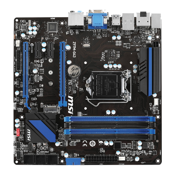
  • Page 93 Guide Rapide Des Connecteurs DIMM3 CPU Socket DIMM2 DIMM4 JBAT1 DIMM1 CPUFAN JPWR2 SYSFAN2 Panneau arrière JPWR1 JUSB4 PCI_E1 M2_1 SATA5_6 PCI_E2 SATA3_4 PCI_E3 JTPM1 SATA1_2 PCI_E4 JCI1 JFP1 JFP2 JAUD1 JUSB2 JUSB1 JUSB3 JCOM1 SYSFAN1 JLPT1 Fr-5...
  • Page 94 Guide référence des connecteurs Noms de ports Types des ports Page Panneau arrière Fr-7 LGA1150 CPU Socket Fr-9 CPUFAN,SYSFAN1~2 Connecteurs d'alimentation du ventilateur Fr-19 DIMM1~4 Emplacements de mémoire Fr-13 JAUD1 Connecteur audio avant Fr-23 JBAT1 Cavalier d’effacement CMOS Fr-25 JCI1 Connecteur intrusion châssis Fr-22 JCOM1...
  • Page 95 Guide rapide du panneau arrière S/PDIF-Out Port PS/2 optique Combo clavier/ Port VGA Port LAN souris Ligne-In RS-Out HDMI Ligne-Out CS-Out SS-Out Port USB 2.0 DisplayPort Port USB 3.0 Port DVI-D ▶ Port PS/2 combo clavier/ souris Combinaison d'un connecteur souris / clavier DIN PS/2 pour une souris ou un clavier PS/2 ®...
  • Page 96 ▶ Port DisplayPort Le port DisplayPort est une interface d'affichage numérique standard. Ce connecteur sert à relier un moniteur avec les entrées DisplayPort. ® ▶ Port HDMI Le High-Definition Multimedia Interface est une interface audio/vidéo tout-numérique, qui est capable de transmettre des flux décompressés. HDMI supporte toutes les formes de TV, y compris le standard, l’amélioré, ou les vidéos hautes définitions, plus l’audio numérique multicanal sur un simple câble.
  • Page 97 Processeur : CPU Introduction du CPU LGA 1150 A la surface du CPU LGA 1150 vous noterez deux encoches et un triangle jaune servant à aligner le CPU dans la bonne position sur la carte mère. Le triangle jaune corresponde à la Pin 1. Encoche Encoche Le triangle jaune corresponde à...
  • Page 98 Installation du CPU et son ventilateur Quand vous installez un CPU, assurez-vous toujours que le CPU soit équipé d’un ventilateur, qui est nécessaire pour éviter la surchauffe et maintenir la stabilité. Suivez les instruction suivantes pour installer le CPU et son ventilateur correctement. Une installation incorrecte peut endommager votre CPU et la carte mère.
  • Page 99 3. Alignez les encoches et les clés d’alignement du socket. Abaissez le CPU en ligne droite, évitez de faire basculer ou glisser le CPU dans l’emplacement. Vérifiez qu'il est bien installé dans la bonne direction. 4. Fermez et glissez le plaque de charge sous le bouton de rétention. Fermez et engagez le levier de charge.
  • Page 100 7. Localisez le connecteur du ventilateur CPU sur la carte mère. 8. Placez le ventilateur sur la carte mère avec son câble face au connecteur du ventilateur. Les éléments de fixation doivent correspondre aux trous sur la carte. Connecteur de ventilateur CPU 9.
  • Page 101 Mémoire Ces emplacements DIMM sont destinés à installer les modules de mémoire. DIMM1 DIMM2 DIMM3 DIMM4 Démonstration de vidéo Voir le vidéo sur l'installation des mémoires sur le site ci-dessous. http://youtu.be/76yLtJaKlCQ Règle de population en mode double canal En mode de double canal, les modules de mémoire peuvent transmettre et recevoir simultanément deux lignes de données.
  • Page 102 Trous Taraudés de Montage Avant d’installer votre carte mère, il faut d’abord installer les socles de montage néce saires sur le plateau de montage du boîtier de l’ordinateur. Si le boîtier de l’ordinateur est accompagné par un panneau Entrée/ Sortie arrière, veuillez le remplacer et utiliser celui qui est fournit dans la boîte de la carte.
  • Page 103 Connecteurs d’alimentation Démonstration de vidéo Voir le vidéo sur l’installation des connecteurs d’alimentation sur le site ci-dessous. http://youtu.be/gkDYyR_83I4 JPWR1~2 : Connecteur d'alimentation ATX Ce connecteur vous permet de relier une alimentation ATX. Pour cela, alignez le câble d’alimentation avec le connecteur et appuyez fermement le câble dans le connecteur. Si ceci est bien fait, la pince sur le câble d’alimentation doit être accrochée sur le connecteur d’alimentation de la carte mère.
  • Page 104 Emplacements d’extension Cette carte mère contient de nombreux ports pour les cartes d’extension, tels que les cartes graphiques ou les cartes audio. PCI_E1~4 : Emplacement d’extension PCIe L'emplacement PCIe supporte l'interface de carte d'extension PCIe. Emplacement PCIe 3.0 x16 Emplacement PCIe 2.0 x4 Emplacement PCIe 2.0 x1 Important •...
  • Page 105 Une ou plusieurs cartes vidéo ajoutées peuvent améliorer fortement la performance graphique du système. Pour une compatibilité parfaite, nous vous recommandons d’utiliser des cartes graphiques MSI. Démonstration de vidéo Voir le vidéo sur l’installation d’une carte graphique dans l’emplacement PCIe x16 avec verrou papillon sur le site ci-dessous.
  • Page 106 Connecteurs internes SATA1~6 : Connecteurs SATA Ce connecteur est un port d’interface SATA haut débit. Chaque connecteur peut être relié à un appareil SATA. Les appareils SATA sont des disques durs (HDD), disque état solide (SSD), et lecteurs optiques (CD/ DVD/ Blu-Ray). Démonstration de vidéo Voir le vidéo sur l’installation d’un SATA HDD.
  • Page 107 CPUFAN,SYSFAN1~2 : Connecteur d’alimentation du ventilateur Les connecteurs d’alimentation du ventilateur supportent les ventilateurs de type +12V. Si la carte mère est équipée d’un moniteur du matériel système intégré, vous devrez utiliser un ventilateur spécial pourvu d’un capteur de vitesse afin de contrôler le ventilateur de l’unité...
  • Page 108 JFP1, JFP2 : Connecteur panneau système Ces connecteurs se connectent aux interrupteurs et LEDs du panneau avant. Le JFP1 est conforme au guide de conception de la connectivité Entrée/sortie du panneau avant Intel . Lors de l’installation des connecteurs du panneau avant, veuillez utiliser ®...
  • Page 109 • La SuperCharger Technology n’est pas disponible sur tous les modèles de carte mère. Veuillez vous référer au site MSI pour vérifier si votre carte mère est équipé de la SuperCharger Technology. • Pour l’iPad, JUSB1 (marqué rouge) peut aussi charger l’iPad en état S3, S4, S5.
  • Page 110 JUSB4 : Connecteurs d’extension USB 3.0 Le port USB 3.0 est rétro-compatible avec les périphériques USB 2.0. Il supporte un taux de transfert jusqu’à 5 Gbit/s (Super-Vitesse). Important • Notez que les pins de VCC et GND doivent être branchées correctement afin d’éviter tout dommage possible.
  • Page 111 JAUD1 : Connecteur audio panneau avant Ce connecteur vous permet de connecter un audio sur le panneau avant.Il est conforme au guide de conception de la connectivité Entrée/sortie du panneau avant Intel ® M2_1 : Port M.2 Le port M.2 supporte soit le module M.2 SATA 6Gb/s ou celui M.2 PCIe. Important •...
  • Page 112 JTPM1 : Connecteur de Module TPM Ce connecteur est relié à un module TPM (Trusted Platform Module) en option. Veuillez vous référer au manuel du module TPM pour plus d’information détaillée. JLPT1 : Connecteur de port Parallèle Ce connecteur sert à connecter un support de port parallèle optionnel. Le port parallèle est un port d’imprimante standard qui supporte les modes Enhanced Parallel Port (EPP) et Extended Capabilities Parallel Port (ECP).
  • Page 113 Cavaliers JBAT1 : Cavalier d’effacement CMOS Il y a un CMOS RAM intégré, qui est alimenté par une batterie externe située sur la carte mère, destiné à conserver les données de configuration du système. Avec le CMOS RAM, le système peut lancer automatiquement le système d’exploitation chaque fois qu’il est allumé.
  • Page 114 Indicateurs d'état LED MSI LED Tableau d'état LED Le tableau suivant décrit l'état d'indicateurs LED. Etat LED Description Allumé Debug Fr-26...
  • Page 115 Veuillez suivre les étapes suivantes pour installer les pilotes et les utilitaires pour votre ordinateur neuf. 1. Insérez le disque de pilote MSI dans le lecteur optique. L'écran de réglages apparaît automatiquement si l'autorun est activé dans le système d'exploitation.
  • Page 116 Configuration BIOS CLICK BIOS est développé par MSI qui fournit une interface graphique utilisateur pour régler les paramètres du BIOS a l'aide de la souris et du clavier. Avec CLICK BIOS, vous pouvez modifier les réglages BIOS, surveiller la température du CPU, choisir la priorité...
  • Page 117 Vue d'ensemble Entrer dans le BIOS, l'écran suivant apparaît. Indicateur température Favori Langue Information du système Barre priorité de périphérique Bouton virtuel démarrage OC Genie Sélection du Sélection du menu BIOS menu BIOS Ecran de menu ▶ Sélection du menu BIOS Les options suivantes sont disponibles : ■...
  • Page 118 Activer ou désactiver la fonction OC Genie en cliquant sur ce bouton. Lorsqu’il est activé, le bouton s’allume. Activer la fonction OC Genie peut automatiquement overclocker avec le profil d’overclocking optimisé MSI. Important Il est conseillé de ne faire aucune modification au menu OC ni de charger les valeurs par défaut après l'activation de la fonction OC Genie.
  • Page 119 Opération Vous pouvez contrôler le réglage BIOS avec la souris et le clavier. La liste ci-dessous décrit les opérations des touches raccourcis et de la souris. Touches Souris Description <↑↓→← > Choisir un article Choisir un champ <Enter> Choisir une icône/ un domaine Cliquer/ Double-cliquer le bouton gauche <Esc>...
  • Page 120 OC Menu Ce menu est destiné aux utilisateur avancés souhaitant overclocker la carte mère. Important • L’Overclocking manuel du PC n’est recommandé que pour les utilisateurs avancés. • L’Overclocking n’est pas garanti, et une mauvaise manipulation peut invalider votre garantie et endommager sévèrement votre matériel. •...
  • Page 121 ▶ Intel Turbo Boost [Enabled]* Active ou désactive Intel Turbo Boost. Ce menu, pour le mode Simple, apparaît ® lorsque le CPU installé prend cette fonction en charge. [Enabled] Active la fonction d'augmenter automatiquement les performances du CPU, supérieures à la spécification nominale lorsque le système exige un état de performance de plus élevée.
  • Page 122 ▶ DRAM Timing Mode [Auto] Choisit le mode de latences mémoire. [Auto] DRAM timings sera déterminé selon le SPD (Serial Presence Detect) des modules de mémoire installés. [Link] Ceci vous permet de configurer les latences DRAM manuellement pour tous les canaux de mémoire. [UnLink] Ceci vous permet de configurer les latences DRAM manuellement pour chaque canal de mémoire.
  • Page 123 ▶ CPU Core/Ring/GT Voltage Mode [Auto]* Choisit le mode de contrôle pour les tensions du cœur CPU/ Ring/ GT. [Auto] Ce réglage est configuré automatiquement par le BIOS. [Adaptive Mode] Définit la tension adaptative automatiquement pour l’optimisation de la performance du système. [Override Mode] Vous permet de régler la tension manuellement.
  • Page 124 ▶ Hyper-Threading Technology [Enabled] Le processeur utilise la technologie Hyper-Threading pour augmenter le taux de transaction et réduire le temps de réponse utilisateur. La technologie traite les multi cœurs dans le processeur comme des multi processeurs logiques qui exécutent les instructions simultanément. Dans ce cas-là, la performance du système est considérablement augmentée.
  • Page 125 ▶ CPU AES Instructions [Enabled] Active ou désactive le support CPU AES (Advanced Encryption Standard-New Instructions). Ce menu apparaît si le CPU prend cette fonction en charge. [Enabled] Active le support Intel AES. [Disabled] Désactive le support Intel AES. ▶ Intel Adaptive Thermal Monitor [Enabled] Active ou désactive la fonction de régulation adaptative de la température du moniteur Intel pour protéger le CPU contre la surchauffe.
  • Page 126 ▶ Intel Turbo Boost [Enabled] Active ou désactive Intel Turbo Boost. Ce menu, pour le mode Simple, apparaît ® lorsque le CPU installé prend cette fonction en charge. [Enabled] Active la fonction d'augmenter automatiquement les performances du CPU, supérieures à la spécification nominale lorsque le système exige un état de performance de plus élevée.
  • Page 127 Русский Благодарим вас за выбор системной платы серии Z97M-G43/ H97M- G43 (MS-7924 v1.X) Micro-ATX. Материнские платы серии Z97M- G43/ H97M-G43 на бвзе чипсета Intel Z97/ H97 и обеспечивают ® оптимальную производительность системы. Платы серии Z97M-G43/ H97M-G43, обеспечивают высокую производительность и являются...
  • Page 128 - 6x портов USB 3.0 (4 порта на задней панели, 2 порта доступны через внутренние USB разъемы) - 8x портов USB 2.0 (2 порта на задней панели, 6 портов доступны через внутренние USB разъемы*) * Внутренний JUSB1 разъем поддерживает MSI Super Charger. Ru-2...
  • Page 129 ■ Детектирование температуры CPU/Системы ■ Детектирование скорости вентилятора CPU/Системы Mонитор ■ Контроль скорости вентилятора CPU/Системы Функции BIOS ■ 64 Мб флэш (для Z97M-G43) ■ 128 Мб флэш (для H97M-G43) ■ Мультиязычный интерфейс БИОС ■ ACPI 5.0, PnP 1.0a, SM BIOS 2.7, DMI 2.0 ■...
  • Page 130 ■ Small Business Advantage (для H97M-G43) Форм-фактор ■ Micro-ATX ■ 9.6 дюймов x 9.6 дюймов (24.4 см x 24.4 см) Последние сведения о поддержке процессора можно получить по адресу http://www.msi.com/cpu-support/ Дополнительные сведения о совместимых компонентах можно получить по адресу http://www.msi.com/test-report/ Ru-4...
  • Page 131 Краткое руководство по разъемам DIMM3 CPU Socket DIMM2 DIMM4 JBAT1 DIMM1 CPUFAN JPWR2 SYSFAN2 Задняя панель JPWR1 JUSB4 PCI_E1 M2_1 SATA5_6 PCI_E2 SATA3_4 PCI_E3 JTPM1 SATA1_2 PCI_E4 JCI1 JFP1 JFP2 JAUD1 JUSB2 JUSB1 JUSB3 JCOM1 SYSFAN1 JLPT1 Ru-5...
  • Page 132 Справочное руководство по разъемам Наименование порта Тип порта Страница Разъемы на задней панели Ru-7 Разъем LGA1150 CPU Ru-9 CPUFAN,SYSFAN1~2 Разъемы питания вентиляторов Ru-19 DIMM1~4 Слоты для модулей памяти Ru-13 JAUD1 Аудиоразъем на передней панели Ru-23 JBAT1 Джампер очистки данных CMOS Ru-25 JCI1 Разъем...
  • Page 133 Краткое руководство по работе с задней панелью комбинированный Оптический порт PS/2 Выход S/PDIF Порт VGA клавиатуры/мыши Порт LAN RS-Выход Линейный вход HDMI Линейный CS-Выход выход Микрофон SS-Выход Порт USB 2.0 DisplayPort Порт USB 3.0 Порт DVI-D ▶ Комбинированные порты PS/2 клавиатуры/мыши Комбинированный...
  • Page 134 ▶ DisplayPort DisplayPort — это цифровой интерфейс для подключения монитора. Данный разъем используется для подключения монитора с разъемом DisplayPort. ® ▶ Порт HDMI Мультимедийный интерфейс высокой четкости (HDMI) представляет собой полностью цифровой аудио- видеоинтерфейс, позволяющий передавать несжатые потоки данных. Интерфейс HDMI обеспечивает передачу ТВ-сигнала по...
  • Page 135 выполнением разгона системы убедитесь в том, что все компоненты системы смогут выдержать разгон. Производитель не рекомендует использовать параметры, выходящие за пределы технических характеристик устройств. Гарантия MSI не распространяется на повреждения и другие возможные последствия ненадлежащей эксплуатации и несоблюдения технических характеристик изделия.
  • Page 136 Установка ЦП и радиатора При установке процессоора обязательно установите радиатор ЦП.Радиатор ЦП предупреждает перегревание и обеспечивает стабильность работы системы. Ниже представлены инструкции по правильной установке процессора и радиатора ЦП. Неправильная установка приводит к выходу из строя процессора и материнской платы. Видео...
  • Page 137 3. Совместите выемки на процессоре с ключами совмещения на сокете. Опустите процессор вниз без наклона. Движение процессора в сокете недопустимо. Проверьте надежность установки процессора в сокете. 4. Закройте и сдвиньте прижимную пластину под ручку удержания. Закройте и зацепите рычаг фиксации. Выемки...
  • Page 138 7. Найдите разъем для подключения вентилятора ЦП на материнской плате. 8. Установите кулер на материнскую плату, направив его кабель в сторону разъема для подключения вентилятора. Разъем подключения вентилятора 9. Нажмите на радиатор сверху так, чтобы закрепить четыре защелки в отверстиях на материнской плате. Нажмите на защелки для закрепления вентилятора.
  • Page 139 Память Разъемы DIMM предназначены для установки модулей памяти. DIMM1 DIMM2 DIMM3 DIMM4 Видео Демонстрация Смотрите видео, чтобы узнать как установить память по указанному адресу. http://youtu.be/76yLtJaKlCQ Правила заполнения гнезд при использовании двухканального режима Dual-Channel В двухканальном режиме модули памяти могут одновременно передавать и получать...
  • Page 140 Отверстия под установочные винты Для установки материнской платы на монтажной плате системного блока сначала установите необходимые установочные стойки. Если в комплект поставки системного блока входит задняя панель ввода-вывода, замените ее задней панелью ввода-вывода, которая поставляется с материнской платой. Задняя панель ввода-вывода без труда устанавливается в системном блоке...
  • Page 141 Электропитание Видео Демонстрация Смотрите видео,чтобы узнать как установить разъем питания. http://youtu.be/gkDYyR_83I4 JPWR1~2: Разъемы питания ATX Эти разъемы предназначены для подключения разъема питания ATX. Для подключения ATX разъема питания совместите кабель питания с разъемом и прочно закрепите его. При правильном выполнении подключения защелка на кабеле...
  • Page 142 Слоты расширения Данная материнская плата содержит множество разъемов для установки плат расширения, в частности, дискретных видеокарт или звуковых карт. PCI_E1~4: Слоты Расширения PCIe Слот PCIe поддерживает платы расширения с интерфейсом PCIe. PCIe 3.0 x16 слот PCIe 2.0 x4 слот PCIe 2.0 x1 слот Внимание...
  • Page 143 в CPU, но Вы так же можете значительно повысит графическую производительность системы, путем добавление одной или нескольких дискретных видеокарт в слоты расширения. Для лучшей совместимости рекомендуется использовать графические карты MSI. Видео Демонстрация Смотрите видео,чтобы узнать как установить видеокарту на слоте...
  • Page 144 Внутренние разъемы SATA1~6: Разъемы SATA Данный разъем является высокоскоростным интерфейсом SATA. К любому разъему SATA можно подключить одно устройство SATA. К устройствам SATA относятся жесткие диски, твердотельные накопители и накопители на оптических дисках (компакт-диски/ DVD-диски/ Blu-Ray-диски). Видео Демонстрация Смотрите видео,чтобы узнать как установить SATA жесткие...
  • Page 145 CPUFAN,SYSFAN1~2: Разъемы питания вентиляторов Разъемы питания вентиляторов поддерживают вентиляторы с питанием +12 В. Если на системной плате установлена микросхема аппаратного мониторинга, необходимо использовать специальные вентиляторы с датчиками скорости для использования функции управления вентиляторами. Обязательно подключите все системные вентиляторы. Некоторые системные вентиляторы невозможно подключить...
  • Page 146 JFP1, JFP2: Разъемы панели системы Эти разъемы служат для подключения кнопок и светодиодных индикаторов, расположенных на передней панели. Разъем JFP1 соответствует стандартам Intel Front Panel I/O Connectivity Design. При установке разъемов передней ® панели для удобства используются переходники и кабели, входящие в комплект поставки.
  • Page 147 плееры, принтеры, модемы и т. д. Разъем JUSB1 (красный значок) поддерживает новую технологию SuperCharger от компании MSI, которая обеспечивает ускоренную зарядку сотового телефона или другого устройства, подключаемого к разъему USB. Для активации этой функции установите приложение MSI SuperCharger в свой компьютер. При...
  • Page 148 JUSB4: Разъем расширения USB 3.0 Порт USB 3.0 обратно совместим с устройствами USB 2.0. Он поддерживает скорость передачи данных до 5 Гбит/с(SuperSpeed). Внимание • Помните, что во избежание повреждений необходимо правильно подключать контакты VCC и GND. • Для использования устройства USB 3.0 подключитесь к разъему USB 3.0 с помощью...
  • Page 149 JAUD1: Аудиоразъем на передней панели Этот разъем служит для подключения аудиоразъема на передней панели системного блока. Этот разъем соответствует стандарту Intel Front Panel I/O ® Connectivity Design. M2_1: Порт M.2 Порт M.2 поддерживает как модули M.2 SATA 6Гб/с, так и модули M.2 PCIe. Внимание...
  • Page 150 JTPM1: Разъем модуля ТРМ Данный разъем подключается к модулю ТРМ (Trusted Platform Module). Дополнительные сведения см. в описании модуля безопасности ТРМ. JLPT1: Разъем параллельного порта Этот коннектор используется для подключения опциональной планки параллельного порта. Параллельный порт-это стандартный порт для принтера. Он...
  • Page 151 Джампер JBAT1: Джампер очистки данных CMOS На плате установлена CMOS память с питанием от батарейки для хранения данных о конфигурации системы. С помощью памяти CMOS операционная система (ОС) автоматически загружается каждый раз при включении. Для сброса конфигурации системы (очистки данных CMOS памяти), воспользуйтесь этой перемычкой.
  • Page 152 Световые индикаторы MSI LED Таблица состояния индикатора В следующей таблице описаны состояния светодиодных индикаторов. Состояние Индикатор Описание индикатора Вкл. Загрузка Ru-26...
  • Page 153 Установка драйверы и утилит Для установки драйверов и утилит на своем компьютере следуйте приведенным ниже указаниям. 1. Вставьте диск с драйверами MSI Driver Disc в привод для оптических дисков. Если в операционной системе включена функция автозапуска, автоматически отобразится утилита installer.
  • Page 154 на экране утилиты "MSI Fast Boot". Внимание • Не забудьте установить “MSI Fast Boot” до того как войти в настройки BIOS. • Для улучшения работы системы содержимое каждого из разделов BIOS, рассматриваемое в данной главе, постоянно совершенствуется. Поэтому для новых версий BIOS оно может несколько отличаться от данного описания, которое...
  • Page 155 Общие Сведения После входа в BIOS отображается следующий экран. Мониторинг температур Избранное Язык Системная Информация Приоритет загрузочных Кнопка устройств Virtual OC Genien Выбор Выбор меню BIOS меню BIOS Экран просмотра раздела ▶ Выбор меню BIOS Доступны следующие опции: ■ SETTINGS - В данном меню указывают параметры настройки для микропроцессора, загрузочного...
  • Page 156 ▶ Кнопка Virtual OC Genie Включает или выключает функции OC Genie, при нажатии кнопки. Данная кнопка мигает при включении. Включение функции OC Genie приводит к автоматическому разгону с оптимизированным профилем MSI. Внимание Мы рекомендуем не делать никаких изменений в меню OC и не загружать...
  • Page 157 Работа Вы можете управлять параметрами настройки BIOS с помощью мыши и клавиатуры. В нижеследующей таблице представлен перечень и описание «клавиш быстрого вызова» и функций мыши. Клавиша Mыши Описание быстрого вызова <↑↓→← > Выбор элемента Перемещение указателя <Enter> Выбор значка/ поля Щелчок/ Двойной...
  • Page 158 Меню OC Данное меню предназначено для опытных пользователей и предоставляет возможности для "разгона" системы. Внимание • Разгонять ПК вручную рекомендуется только опытным пользователям. • Производитель не гарантирует успешность разгона. Неправильное выполнение разгона может привести к аннулированию гарантии и серьезному повреждению оборудования. •...
  • Page 159 ▶ Intel Turbo Boost [Enabled]* Включение или выключение Intel Turbo Boost. Этот пункт появляется, когда ® установленный процессор поддерживает данную функцию. [Enabled] Включение этой функции приводит к автоматическому увеличению производительности процессора. [Disabled] Функция выключена. ▶ Legacy Tweaking [Disabled]* Включение или выключение для повышения производительности устаревших приложений...
  • Page 160 ▶ Extreme Memory Profile (X.M.P) [Disabled] X.M.P. (Extreme Memory Profile) является технологией разгона для модулей памяти. Этот пункт доступен при установке модулей памяти с поддержкой технологии XMP. [Disabled] Функция выключена. [Profile 1] Использует настройки разгона Профиль 1 для установленного модуля памяти XMP. [Profile 2] Использует...
  • Page 161 < Настройка напряжения > ▶ SVID Communication [Auto]* Включение или выключение поддержки SVID (Serial Voltage Identification). [Auto] Этот параметр будет настроен автоматически с помощью BIOS. [Enabled] Фаза PWM будет изменена в зависимости от SVID процессора (Serial Voltage Identification). [Disabled] Выключение поддержки SVID (Serial Voltage Identification). ▶...
  • Page 162 ▶ MEMORY-Z Нажмите <Enter> для входа в подменю. В подменю выделены все параметры и тайминги установленной памяти. Для просмотра этой информации в любое время нажмите на кнопку [F5]. ▶ DIMMXX Memory SPD Нажмите <Enter> для входа в подменю. Это подменю показывает информацию...
  • Page 163 ▶ Hardware Prefetcher [Enabled] Включение или выключение аппаратной предвыборки (MLC Streamer prefetcher). [Enabled] Позволяет автоматически реализовывать предвыборку данных и инструкций из памяти в кэш L2 для настройки производительности процессора. [Disabled] Выключение аппаратной предвыборки. ▶ Adjacent Cache Line Prefetch [Enabled] Включение или выключение предвыборки процессора (MLC Spatial prefetcher). [Enabled] Включение...
  • Page 164 ▶ LakeTiny Feature [Disabled] Включение или выключение технологии Intel Lake Tiny с iRST для SSD. Этот элемент появляется, когда установленный процессор поддерживает данную функцию и при включении “Intel C-State”. [Enabled] Повышение динамической нагрузки IO скорректированной производительности для ускорения скорости SSD. [Disabled] Функция...
  • Page 165 Installation/ Установка This chapter provides demonstration diagrams about how to install your computer. Some of the installations also provide video demonstrations. Please link to the URL to watch it with the web browser on your phone or tablet. You may have even link to the URL by scanning the QR code. Das vorliegende Kapitel bietet die Demo-Diagrammen, wie Sie Ihren Computer zu installieren.
  • Page 166 http://youtu.be/bf5La099urI...
  • Page 168 Memory/ Speicher/ Mémoire/ Памяти http://youtu.be/76yLtJaKlCQ...
  • Page 169 Motherboard/ Carte mère/ Материнские платы...
  • Page 171 Power Connector/ ATX-Stromanshcluss/ Connecteurs d'alimentation/ Pазъема питания http://youtu.be/gkDYyR_83I4 oder или...
  • Page 173 SATA HDD http://youtu.be/RZsMpqxythc oder или oder или...
  • Page 174 4.2 cm 6 cm 8 cm A-10...
  • Page 175 Front Panel Connector/ Frontpanel Anschluss/ Connecteur panneau avant/ Pазъемов передней панели JFP1 http://youtu.be/DPELIdVNZUI JAUD1 A-11...
  • Page 176 Peripheral Connector/ Peripheriestecker/ Connecteur périphérique/ Периферийных разъемов USB2.0 oder или USB3.0 A-12...
  • Page 177 Graphics Card/ Grafikkarte/ Carte graphique/ Bидеокарты http://youtu.be/mG0GZpr9w_A A-13...
  • Page 178 A-14...

Ce manuel est également adapté pour:

H97m-g43Ms-7924