Table des Matières

Publicité

Les langues disponibles

Les langues disponibles

Liens rapides

Preface
Z97 GAMING 7
Motherboard
G52-79161X3

Publicité

Table des Matières
loading

Sommaire des Matières pour MSI Z97 GAMING 7

  • Page 1 Preface Z97 GAMING 7 Motherboard G52-79161X3...
  • Page 2: Trademarks

    Copyright Notice The material in this document is the intellectual property of MICRO-STAR INTERNATIONAL. We take every care in the preparation of this document, but no guarantee is given as to the correctness of its contents. Our products are under continual improvement and we reserve the right to make changes without notice.
  • Page 3: Smartphone Application

    If a problem arises with your system and no solution can be obtained from the user’s manual, please contact your place of purchase or local distributor. Alternatively, please try the following help resources for further guidance. Visit the MSI website for technical guide, BIOS updates, driver updates, and other information: http://www.msi.com/service/download/ Contact our technical staff at: http://register.msi.com/...
  • Page 4: Safety Instructions

    Safety Instructions ■ Always read the safety instructions carefully. ■ Keep this User’s Manual for future reference. ■ Keep this equipment away from humidity. ■ Lay this equipment on a reliable flat surface before setting it up. ■ The openings on the enclosure are for air convection hence protects the equipment from overheating.
  • Page 5: Fcc-B Radio Frequency Interference Statement

    FCC-B Radio Frequency Interference Statement This equipment has been tested and found to comply with the limits for a Class B digital device, pursuant to Part 15 of the FCC Rules. These limits are designed to provide reasonable protection against harmful interference in a residential installation. This equipment generates, uses and can radiate radio frequency energy and, if not installed and used in accordance with the instructions, may cause harmful interference to radio communications.
  • Page 6: Radiation Exposure Statement

    Radiation Exposure Statement This equipment complies with FCC radiation exposure limits set forth for an uncontrolled environment. This equipment and its antenna should be installed and operated with minimum distance 20 cm between the radiator and your body. This equipment and its antenna must not be co-located or operating in conjunction with any other antenna or transmitter.
  • Page 7: Battery Information

    Replace only with the same or equivalent type recommended by the manufacturer. Chemical Substances Information In compliance with chemical substances regulations, such as the EU REACH Regulation (Regulation EC No. 1907/2006 of the European Parliament and the Council), MSI provides the information of chemical substances in products at: http://www.msi.com/html/popup/csr/evmtprtt_pcm.html Preface...
  • Page 8: Weee (Waste Electrical And Electronic Equipment) Statement

    MSI will comply with the product take back requirements at the end of life of MSI-branded products that are sold into the EU. You can return these products to local collection points.
  • Page 9 MSI će poštovati zahtev o preuzimanju ovakvih proizvoda kojima je istekao vek trajanja, koji imaju MSI oznaku i koji su prodati u EU. Ove proizvode možete vratiti na lokalnim mestima za prikupljanje.
  • Page 10 MSI si adeguerà a tale Direttiva ritirando tutti i prodotti marchiati MSI che sono stati venduti all’interno dell’Unione Europea alla fine del loro ciclo di vita.
  • Page 11: Table Des Matières

    CONTENTS ▍ English ...................... En-1 Motherboard Specifications ................En-2 Connectors Quick Guide ..................En-5 Back Panel Quick Guide ..................En-7 CPU (Central Processing Unit) ................En-9 Memory ......................En-13 Mounting Screw Holes ..................En-14 Power Supply ....................En-15 Expansion Slots ....................En-16 Video/ Graphics Cards ..................En-17 Internal Connectors ..................En-18 Voltage Checkpoints ..................En-26 Buttons ......................En-27 Jumper ......................En-29...
  • Page 12 Français ..................... Fr-1 Spécifications ......................Fr-2 Guide Rapide Des Connecteurs .................Fr-5 Guide rapide du panneau arrière ................Fr-7 Processeur : CPU ....................Fr-9 Mémoire ......................Fr-13 Trous Taraudés de Montage ................Fr-14 Connecteurs d’alimentation ................Fr-15 Emplacements d’extension ................Fr-16 Cartes Vidéo/ Graphics ..................Fr-17 Connecteurs internes ..................Fr-18 Point de vérification tension ................Fr-26 Boutons ......................Fr-27 Cavaliers ......................Fr-29...
  • Page 13 Installation/ Установка ................A-1 CPU ........................A-2 Memory/ Speicher/ Mémoire/ Памяти ..............A-4 Motherboard/ Carte mère/ Материнские платы ..........A-5 Power Connector/ ATX-Stromanshcluss/ Connecteurs d'alimentation/ Pазъема питания ........................A-7 SATA HDD ......................A-9 M.2 ........................A-10 Front Panel Connector/ Frontpanel Anschluss/ Connecteur panneau avant/ Pазъемов передней панели ................A-11 Peripheral Connector/ Peripheriestecker/ Connecteur périphérique/ Периферийных...
  • Page 15: English

    English Thank you for choosing the Z97 GAMING 7 Series (MS-7916 v1.X) ATX motherboard. The Z97 GAMING 7 Series motherboards are based on Intel ® Z97 chipset for optimal system efficiency. Designed to fit the advanced Intel ® LGA1150 processor, the Z97 GAMING 7 Series motherboards deliver a high...
  • Page 16: Motherboard Specifications

    ■ ASMedia ASM1074 Chipset 4x USB 3.0 ports on the back panel ■ ASMedia ASM1042 Chipset 2x USB 3.0 ports on the back panel * Internal JUSB1 connector supports MSI Super Charger. Audio ■ Realtek ALC1150 Codec ® 7.1-Channel High Definition Audio...
  • Page 17 ■ 1x Killer E2205 Gigabit LAN controller* * The Killer Network Manager is only available for Windows 7 and Windows 8/ 8.1 currently. The supported drivers for other operating systems would be available on the website if provided by vendor. Back Panel ■...
  • Page 18 ■ Killer Network Manager Form ■ ATX Form Factor ■ 12 in. x 9.6 in. (30.5 cm x 24.4 cm) Factor For the latest information about CPU, please visit http://www.msi.com/cpu-support/ For more information on compatible components, please visit http://www.msi.com/test-report/ En-4...
  • Page 19: Connectors Quick Guide

    Connectors Quick Guide DIMM3 DIMM2 DIMM4 SYSFAN1 DIMM1 CPUFAN1 JPWR2 CPU Socket CPUFAN2 SYSFAN3 Back Panel JPWR1 PCI_E1 JCI1 SLOW_1 PCI_E2 JUSB3 PCI_E3 SATA1_2 JBAT1 PCI_E4 SATA3_4 PCI_E5 SATA5_6 PCI_E6 SATA7_8 M2_1 PCI_E7 BIOS_SW1 JFP1 SYSFAN2 JAUD1 JCOM1 JTPM1 JFP2 JUSB2 AUDPWR1 JUSB1...
  • Page 20 Connectors Reference Guide Port Name Port Type Page Back Panel I/O Ports En-7 AUD_SW1 Audio Power Switch En-31 AUDPWR1 Direct Audio Power Connector En-23 BIOS_SW1 Multi-BIOS Switch En-30 LGA1150 CPU Socket En-9 CPUFAN1~2,SYSFAN1~3 Fan Power Connectors En-19 DIMM1~4 DDR3 Memory slots En-13 V-Check Connectors En-26...
  • Page 21: Back Panel Quick Guide

    Back Panel Quick Guide Optical PS/2 Keyboard/ S/PDIF-Out USB 3.0 Port Mouse Combo LAN Port Port* Line-In RS-Out USB 3.0 Port HDMI Line-Out CS-Out HDMI SS-Out USB 2.0 Port* Clear CMOS DisplayPort USB 3.0 Port Button * Gaming Device Port. ▶...
  • Page 22 ▶ Optical S/PDIF-Out This S/PDIF (Sony & Philips Digital Interconnect Format) connector is provided for digital audio transmission to external speakers through an optical fiber cable. ® ▶ HDMI Port The High-Definition Multimedia Interface (HDMI) is an all-digital audio-video interface that is capable of transmitting uncompressed streams.
  • Page 23: Cpu (Central Processing Unit)

    This motherboard is designed to support overclocking. Before attempting to overclock, please make sure that all other system components can tolerate overclocking. Any attempt to operate beyond product specifications is not recommend. MSI does not guarantee the damages or risks caused by inadequate operation beyond product specifications.
  • Page 24: Cpu & Heatsink Installation

    CPU & Heatsink Installation When installing a CPU, always remember to install a CPU heatsink. A CPU heatsink is necessary to prevent overheating and maintain system stability. Follow the steps below to ensure correct CPU and heatsink installation. Wrong installation can damage both the CPU and the motherboard.
  • Page 25 3. Align the notches with the socket alignment keys. Lower the CPU straight down, without tilting or sliding the CPU in the socket. Inspect the CPU to check if it is properly seated in the socket. 4. Close and slide the load plate under the retention knob. Close and engage the load lever.
  • Page 26 7. Locate the CPU fan connector on the motherboard. 8. Place the heatsink on the motherboard with the fan’s cable facing towards the fan connector and the fasteners matching the holes on the motherboard. CPU fan connector 9. Push down the heatsink until the four fasteners get wedged into the holes on the motherboard.
  • Page 27: Memory

    Memory These DIMM slots are used for installing memory modules. DIMM1 DIMM2 DIMM3 DIMM4 Video Demonstration Watch the video to learn how to install memories. http://youtu.be/76yLtJaKlCQ Dual-Channel mode Population Rule In Dual-Channel mode, the memory modules can transmit and receive data with two data bus channels simultaneously.
  • Page 28: Mounting Screw Holes

    Mounting Screw Holes When installing the motherboard, first install the necessary mounting stands required for an motherboard on the mounting plate in your computer case. If there is an I/O back plate that came with the computer case, please replace it with the I/O backplate that came with the motherboard package.
  • Page 29: Power Supply

    Power Supply Video Demonstration Watch the video to learn how to install power supply connectors. http://youtu.be/gkDYyR_83I4 JPWR1~2: ATX Power Connectors These connectors allow you to connect an ATX power supply. To connect the ATX power supply, align the power supply cable with the connector and firmly press the cable into the connector.
  • Page 30: Pci_E1~7: Pcie Expansion Slots

    Expansion Slots This motherboard contains numerous slots for expansion cards, such as discrete graphics or audio cards. PCI_E1~7: PCIe Expansion Slots The PCIe slot supports the PCIe interface expansion card. PCIe 3.0 x16 Slot PCIe 2.0 x1 Slot Important When adding or removing expansion cards, always turn off the power supply and unplug the power supply power cable from the power outlet.
  • Page 31: Video/ Graphics Cards

    Adding on one or more discrete video cards will significantly boost the system’s graphics performance. For best compatibility, MSI graphics cards are recommended. Video Demonstration Watch the video to learn how to install a graphics card on PCIe x16 slot with butterfly lock.
  • Page 32: Internal Connectors

    Internal Connectors SATA1~8: SATA Connectors This connector is a high-speed SATA interface port. Each connector can connect to one SATA device. SATA devices include disk drives (HDD), solid state drives (SSD), and optical drives (CD/ DVD/ Blu-Ray). Video Demonstration Watch the video to learn how to Install SATA HDD. http://youtu.be/RZsMpqxythc SATA2 SATA1...
  • Page 33 CPUFAN1~2,SYSFAN1~3: Fan Power Connectors The fan power connectors support system cooling fans with +12V. If the motherboard has a System Hardware Monitor chipset on-board, you must use a specially designed fan with a speed sensor to take advantage of the CPU fan control. Remember to connect all system fans.
  • Page 34 JFP1, JFP2: System Panel Connectors These connectors connect to the front panel switches and LEDs. The JFP1 connector is compliant with the Intel Front Panel I/O Connectivity Design Guide. When ® installing the front panel connectors, please use the optional M-Connector to simplify installation.
  • Page 35 Please only connect one device per USB port to ensure stable charging. Super-Charger Technology is only available on select MSI motherboard models. • Please refer to the MSI website to check if your motherboard has Super-Charger technology. • For iPad, JUSB1 (red mark) can still charge iPad in S3, S4, S5 state.
  • Page 36: Jci1: Chassis Intrusion Connector

    JUSB3: USB 3.0 Expansion Connector The USB 3.0 port is backwards compatible with USB 2.0 devices. It supports data transfer rates up to 5Gbits/s (SuperSpeed). Important • Note that the VCC and GND pins must be connected correctly to avoid possible damage.
  • Page 37 JAUD1: Front Panel Audio Connector This connector allows you to connect the front audio panel located on your computer case. This connector is compliant with the Intel Front Panel I/O Connectivity Design ® Guide. AUDPWR1: Direct Audio Power Connector This connector is used to provide direct power to back panel audio ports. The direct audio power can provide the better audio quality.
  • Page 38: Jtpm1: Tpm Module Connector

    M2_1: M.2 Port The M.2 port supports either M.2 SATA 6Gb/s module or M.2 PCIe module. Important The SATA5 and SATA6 ports will be unavailable when installing a module in the • M.2 port. • Intel RST only supports PCIe M.2 SSD with UEFI ROM, does not support Legacy ROM.
  • Page 39: Jcom1: Serial Port Connector

    JCOM1: Serial Port Connector This connector is a 16550A high speed communication port that sends/receives 16 bytes FIFOs. You can attach a serial device. En-25...
  • Page 40: Voltage Checkpoints

    Voltage Checkpoints These voltage checkpoints are used to measure the current system voltages. A multimeter (not included) will be required to check voltages. FV1: V-Check Connectors To check the voltage, please use the optional voltage checkpoint cables included in the motherboard package. Attach the positive lead of the multimeter to the voltage checkpoint cable and the negative lead to the ground connector.
  • Page 41: Buttons

    BIOS section of the manual for instructions on how to turn off OC Genie from the BIOS. • The usage of OC Genie is at the user’s own risk. Overclocking is never guaranteed by MSI. • To ensure successfully OC Genie usage, MSI components are recommended. En-27...
  • Page 42 POWER1: Power Button This button is used to turn-on and turn-off the system. Press the button once to turn-on or turn-off the system. RESET1: Reset Button This reset button is used to reset the system. Press the button to reset the system. En-28...
  • Page 43: Jumper

    Jumper JBAT1: Clear CMOS Jumper There is CMOS RAM onboard that is external powered from a battery located on the motherboard to save system configuration data. With the CMOS RAM, the system can automatically boot into the operating system (OS) every time it is turned on. If you want to clear the system configuration, set the jumpers to clear the CMOS RAM.
  • Page 44: Bios_Sw1: Multi-Bios Switch

    Preparation: 1. Prepare a bootable USB flash drive. 2. Download the latest BIOS file from the MSI official website at www.msi.com, and then decompress the file. 3. Copy the AFUDE238.exe and the BIOS file to the bootable USB flash drive BIOS recovery steps: 1.
  • Page 45: Slow_1: Slow Mode Booting Switch

    SLOW_1: Slow Mode Booting Switch This switch is used for LN2 cooling solution, that provides the extreme overclocking conditions, to boot at a stable processor frequency and to prevent the system from crashing. Normal Enabled (Default) Important Users will try extreme low temperature overclocking at their own risks. The overclocking results will vary according to the CPU version.
  • Page 46: Led Status Indicators

    LED Status Indicators Debug LED HDD LED BIOS B LED MSI LED BIOS A LED LED Status Table The following table describes the status of LED indicators. LED Status Description Debug Blinking HDD activity BIOS A LED Blue BIOS A in operation...
  • Page 47: Debug Code Led Table

    Debug Code LED Table Please refer to the table below to get more information about the Debug Code LED message. Post Status 02,07 Power on CPU Initialization 03,08 Power on North Bridge Initialization 04,09 Power on South Bridge Initialization Power on Cache Initialization 11~14,32~36,56~5A Early CPU Initialization 15~18,37~3A...
  • Page 48: Drivers And Utilities

    After you install the operating system you will need to install drivers to maximize the performance of the new computer you just built. MSI motherboard comes with a Driver Disc. Drivers allow the computer to utilize your motherboard more efficiently and take advantage of any special features we provide.
  • Page 49: Bios Setup

    "MSI Fast Boot" utility screen. Important • Please be sure to install the “MSI Fast Boot” utility before using it to enter the BIOS setup. • The items under each BIOS category described in this chapter are under continuous update for better system performance. Therefore, the description may be slightly different from the latest BIOS and should be held for reference only.
  • Page 50 Overview After entering BIOS, the following screen is displayed. Temperature monitor My Favorites Language System information Boot device priority bar Virtual OC Genie Button BIOS menu BIOS menu selection selection Menu display ▶ BIOS menu selection The following options are available: ■...
  • Page 51 Enables or disables the OC Genie function by clicking on this button. When enabled, this button will be light. Enabling OC Genie function can automatically overclock with MSI optimized overclocking profile. Important We recommend that you do not to make any modification in OC menu mode and do not to load defaults after enabling the OC Genie function.
  • Page 52 Operation You can control BIOS settings with the mouse and the keyboard. The following table lists and describes the hot keys and the mouse operations. Hot key Mouse Description <↑↓→← > Select Item Move the cursor <Enter> Select Icon/ Field Click/ Double-click the left button <Esc>...
  • Page 53 OC Menu This menu is for advanced users who want to overclock the mainboard. Important • Overclocking your PC manually is only recommended for advanced users. • Overclocking is not guaranteed, and if done improperly, can void your warranty or severely damage your hardware.
  • Page 54 Enables the OC Genie function by virtual button in BIOS or physical button on motherboard. Enabling OC Genie function can automatically overclock the system with MSI optimized overclocking profile. [By BIOS Options] OC Genie function is enabled by clicking the virtual OC Genie button at the top left corner of BIOS setup screen.
  • Page 55 < DRAM Setting > ▶ DRAM Frequency [Auto] Sets the DRAM frequency. Please note the overclocking behavior is not guaranteed. ▶ Adjusted DRAM Frequency Shows the adjusted DRAM frequency. Read-only. ▶ Extreme Memory Profile (X.M.P) [Disabled] X.M.P. (Extreme Memory Profile) is the overclocking technology by memory module. This item will be available when you install the memory modules that support X.M.P.
  • Page 56 < Voltage Setting > ▶ DigitALL Power Press <Enter> to enter the sub-menu. Controls the digital powers related to CPU PWM. ▶ VR 12VIN OCP Expander [Auto] Expands the limitation of VR Over Current Protection with 12V input voltage. The higher expanding value indicates less protection.
  • Page 57 ▶ DRAM Phase Control [Auto] Controls PWM phase proportionally to the DRAM loading. If set to "Auto", BIOS will optimize the DRAM PWM phase automatically. [Auto] This setting will be configured automatically by BIOS. [Disabled] Disables the PWM power phase switching feature. ▶...
  • Page 58 ▶ CPU SA/ IO Analog/ IO Digital Voltage Offset Mode [Auto]* Selects the offset mode for CPU SA/ IO Analog/ IO Digital voltage. This item appears when "CPU SA/IOA/IOD Voltage Mode" sets to [Offset Mode]. [Auto] This setting will be configured automatically by BIOS. Allows you to offset the voltage by positive value mode.
  • Page 59 ▶ Hyper-Threading Technology [Enabled] The processor uses Hyper-Threading technology to increase transaction rates and reduces end-user response times. Intel Hyper-Threading technology treats the multi cores inside the processor as multi logical processors that can execute instructions simultaneously. In this way, the system performance is highly improved.
  • Page 60 ▶ CPU AES Instructions [Enabled] Enables or disables the CPU AES (Advanced Encryption Standard-New Instructions) support. This item appears when a CPU supports this function. [Enabled] Enables Intel AES support. [Disabled] Disables Intel AES support. ▶ Intel Adaptive Thermal Monitor [Enabled] Enables or disables the Intel adaptive thermal monitor function to protect the CPU from overheating.
  • Page 61 ▶ Intel Turbo Boost [Enabled] Enables or disables the Intel Turbo Boost. This item is for Simple mode and ® appears when the installed CPU supports this function. [Enabled] Enables this function to boost CPU performance automatically above rated specifications when system request the highest performance state.
  • Page 63: Deutsch

    Deutsch Danke, dass Sie das Z97 GAMING 7 (MS-7916 v1.X) ATX Motherboard gewählt haben. Diese Z97 GAMING 7 Motherboard basiert auf dem Intel ® Chipsatz und ermöglicht so ein optimales und effizientes System. Entworfen, um den hochentwickelten Intel LGA1150 Prozessor zu unterstützen, stellt ®...
  • Page 64: Spezifikationen

    Anschlussleiste, 4 Anschlüsse stehen durch die internen USB 2.0 Anschlüsse zur Verfügung*) ■ ASMedia ASM1074 Chipsatz 4x USB 3.0 Anschlüsse an der rückseitigen Anschlussleiste ■ ASMedia ASM1042 Chipsatz 2x USB 3.0 Anschlüsse an der rückseitigen Anschlussleiste * Interner JUSB1 Anschluss unterstützt MSI Super Charger. De-2...
  • Page 65 Audio ■ Realtek ALC1150 Codec ® 7,1-Kanal-HD-Audio Unterstützt S/PDIF-Ausgang ■ 1x Killer E2205 Gigabit LAN Controller * Der Killer Network Manager ist derzeit nur für Windows 7 und Windows 8/ 8.1 erhältlich. Die unterstützten Treiber für andere Betriebssysteme würden auf der Website zur Verfügung stehen, wenn vom Lieferanten zur Verfügung gestellt.
  • Page 66 ■ XSplit Gamecaster ■ Killer Network Manager Formfaktor ■ ATX Formfaktor ■ 12 Zoll x 9,6 Zoll (30,5 cm x 24,4 cm) Weitere CPU Informationen finden Sie unter http://www.msi.com/cpu-support/ Die neusten Informationen über kompatible Bauteile finden Sie unter http://www.msi.com/test-report/ De-4...
  • Page 67: Anschlussübersicht

    Anschlussübersicht DIMM3 DIMM2 DIMM4 SYSFAN1 DIMM1 CPUFAN1 JPWR2 CPU Sockel CPUFAN2 SYSFAN3 Rück- tafel JPWR1 PCI_E1 JCI1 SLOW_1 PCI_E2 JUSB3 PCI_E3 SATA1_2 JBAT1 PCI_E4 SATA3_4 PCI_E5 SATA5_6 PCI_E6 SATA7_8 M2_1 PCI_E7 BIOS_SW1 JFP1 SYSFAN2 JAUD1 JCOM1 JTPM1 JFP2 JUSB2 AUDPWR1 JUSB1 AUD_SW1 RESET1...
  • Page 68 Übersicht der Motherboard-Anschlüsse Port-Name Port-Typ Seite Rücktafel E/A-Anschlüsse De-7 AUD_SW1 Audio Power Schalter De-31 AUDPWR1 Direct Audio Power Anschluss De-23 BIOS_SW1 Multi-BIOS Schalter De-30 LGA1150 CPU Sockel De-9 CPUFAN1~2,SYSFAN1~3 Stromanschlüsse für Lüfter De-19 DIMM1~4 DDR3 Speichersteckplätze De-13 Spannungsmesspunkte De-26 JAUD1 Audioanschluss des Frontpanels De-23 JBAT1...
  • Page 69: Rücktafel-Übersicht

    Rücktafel-Übersicht Optischer USB 3.0 PS/2 Tastatur/ S/PDIF Ausgang Maus Combo Anschluss Anschluss* Anschluss RS-Out USB 3.0 Line-In Anschluss CS-Out HDMI Line-Out HDMI SS-Out USB 2.0 Clear CMOS DisplayPort USB 3.0 Anschluss* Taste Anschluss * Spiele-Gerät-Port. ▶ PS/2 Tastatur/Maus Combo Anschluss Die Standard PS/2 Maus/Tastatur Stecker DIN ist für eine PS/2 Maus/Tastatur.
  • Page 70 ▶ Optischer S/PDIF-Ausgang Dieser S/PDIF-Ausgang (Sony & Philips Digital Interconnect Format) dient als digitale Schnittstelle zur Audioausgabe zur den externen Lautsprechern durch ein optisches Faserkabel. ® ▶ HDMI Anschluss Das High-Definition Multimedia Interface (kurz HDMI) ist eine Schnittstelle für die volldigitale Übertragung von dekomprimierten Audio- und Video-Daten.
  • Page 71: Cpu (Prozessor)

    CPU (Prozessor) Erklärung zur LGA 1150 CPU Die Obserseite der LGA 1150 CPU hat zwei Justierungen und ein gelbes Dreieck um die korrekte Ausrichtung der CPU auf dem Motherboard zu gewährleisten. Das gelbe Dreieck des Prozessors definiert die Position des ersten Pins. Kerbe Kerbe Das goldene Dreieck des Prozessors...
  • Page 72: Cpu & Kühlkörper Einbau

    CPU & Kühlkörper Einbau Wenn Sie die CPU einbauen, denken sie bitte daran einen CPU-Kühler zu installieren. Ein CPU-Kühlkörper ist notwendig, um eine Überhitzung zu vermeiden und die Systemstabilität beizubehalten. Befolgen Sie die nachstehenden Schritte, um die richtige CPU und CPU-Kühlkörper Installation zu gewährleisten. Ein fehlerhafter Einbau führt zu Schäden an der CPU und dem Motherboard.
  • Page 73 3. Positionieren Sie die Kerben mit die Justiermarkierungen des Sockels. Setzen Sie die CPU nach unten, ohne Kippen oder Schieben der CPU im Sockel. Begutachten Sie, ob die CPU richtig im Sockel sitzt. 4. Schließen Sie und schieben Sie die Abdeckplatte unter dem Rückhalteknopf. Verschließen Sie den Verschlusshebel.
  • Page 74 7. Machen Sie den CPU-Lüfteranschluss auf dem Motherboard ausfinding. 8. Setzen Sie den Kühlkörper auf die CPU und beachten Sie die Übereinstimmung der Lüfterverankerungen mit den dafür vorgsehenen Löchern auf der Motherboard -Platine. CPU-Lüfteranschluss 9. Drücken Sie nach der korrekten Positionierung des Kühlkörpers die Arretierungsstifte mit leichtem Druck nach unten bis sie einrasten.
  • Page 75: Speicher

    Speicher Die DIMM-Steckplätze nehmen Arbeitsspeichermodule auf. DIMM1 DIMM2 DIMM3 DIMM4 Video-Demonstration Anhand dieses Video an untenstehender Adresse erfahren Sie, wie Sie die Speichermodule installieren. http://youtu.be/76yLtJaKlCQ Populationsregeln für Dual-Kanal-Speicher Im Dual-Kanal-Modus können Arbeitsspeichermodule Daten über zwei Datenbusleitungen gleichzeitig senden und empfangen. Durch Aktivierung des Dual- Kanal-Modus wird die Leistung Ihres Systems verbessert.
  • Page 76: Schraubenlöcher Für Die Montage

    Schraubenlöcher für die Montage Verwenden Sie die dem Motherboard beiliegende I/O-Platte und setzen Sie sie mit leichtem Druck von innen in die Aussparung des Computergehäuses ein. Zur Installation des Motherboards in Ihrem PC-Gehäuse befestigen Sie zunächst die dem Gehäuse beiliegenden Abstandhalter im Gehäuse. Legen Sie das Motherboard mit den Schraubenöffnungen über den Abstandhaltern und schrauben Sie das Motherboard mit den dem Gehäuse beiliegenden Schrauben fest.
  • Page 77: Stromversorgung

    Stromversorgung Video-Demonstration Anhand dieses Video an untenstehender Adresse erfahren Sie, wie Sie die Stromversorgungsstecker installieren. http://youtu.be/gkDYyR_83I4 JPWR1~2: ATX Stromanschlüsse Mit diesem Anschluss verbinden Sie den ATX Stromanschlusse. Achten Sie bei dem Verbinden des ATX Stromanschlusses darauf, dass der Anschluss des Netzteils richtig auf den Anschluss an der Hauptplatine ausgerichtet ist.
  • Page 78: Pci_E1~7: Pcie Erweiterungssteckplätze

    Erweiterungssteckplätze Dieses Motherboard enthält zahlreiche Schnittstellen für Erweiterungskarten, wie diskrete Grafik-oder Soundkarten. PCI_E1~7: PCIe Erweiterungssteckplätze Der PCIe Steckplatz unterstützt PCIe-Erweiterungskarten. PCIe 3.0 x16-Steckplatz PCIe 2.0 x1-Steckplatz Wichtig Achten Sie darauf, dass Sie den Strom abschalten und das Netzkabel aus der Steckdose herausziehen, bevor Sie eine Erweiterungskarte installieren oder entfernen.
  • Page 79: Video/ Grafikkarten

    Video/ Grafikkarten Fall im Prozessor integriert, nutzt dieses Motherboard den im Prozessor befindlichen Grafikprozessor. Zusätzliche Grafikkarten können aber über die auf dem Motherboard verfügbaren Erweiterungssteckplätze eingesetzt werden um die Systemleistung zu erhöhen. Video-Demonstration Anhand dieses Video an untenstehender Adresse erfahren Sie, wie Sie eine Grafikkarte im PCIe x16 Steckplatz mit Butterfly-Verschlüssen installieren.
  • Page 80: Interne Anschlüsse

    Interne Anschlüsse SATA1~8: SATA Anschluss Dieser Anschluss basiert auf der Hochgeschwindigkeitsschnittstelle Serial ATA (SATA). Pro Anschluss kann ein Serial ATA Gerät angeschlossen werden. Zu Serial ATA Geräten gehören Festplatten (HDD), SSD Festplatten (SSD) und optische Laufwerke (CD-/DVD-/Blu-Ray-Laufwerke). Video-Demonstration Anhand dieses Video an untenstehender Adresse erfahren Sie, wie Sie eine SATA-Featplatte installieren.
  • Page 81: Cpufan1~2,Sysfan1~3: Stromanschlüsse Für Lüfter

    CPUFAN1~2,SYSFAN1~3: Stromanschlüsse für Lüfter Die Anschlüsse unterstützen aktive Systemlüfter mit +12V. Ist Ihr Motherboard mit einem Chipsatz zur Überwachung der Systemhardware versehen, dann brauchen Sie einen speziellen Lüfter mit Geschwindigkeitsregelung, um die Vorteile der Steuerung des CPU Lüfters zu nutzen. Vergessen Sie nicht, alle Systemlüftern anzuschließen. Einige Systemlüfter können nicht direkt an dem Motherboard angeschlossen werden und müssen stattdessen mit dem Netzteil direkt verbunden werden.
  • Page 82 JFP1, JFP2: Systemtafelanschlüsse Diese Anschlüsse sind für das Frontpanel angelegt. Sie dienen zum Anschluss der Schalter und LEDs des Frontpanels. JFP1 erfüllt die Anforderungen des “Intel Front ® Panel I/O Connectivity Design Guide”. Bei der Installation des Frontpanel-Anschlüsse, nutzen Sie bitte die optionalen M-Connectors um die Installation zu vereinfachen. Schließen Sie alle Kabel aus dem PC-Gehäuse zunächst an die M-Connectors an und stecken Sie die M-Connectors auf das Motherboard.
  • Page 83 Ladevorgang. • Die Super-Charger Technologie ist nur für ausgewählte MSI Motherboard-Modelle verfügbar. Prüfen Sie bitte anhand der MSI Webseite ob Ihr Motherboard die SuperCharger Technologie unterstützt. • Das iPad kann auch im S3-, S4- und S5-Status über den JUSB1 (rote Markierung) geladen werden.
  • Page 84: Jci1: Gehäusekontaktanschluss

    JUSB3: USB 3.0 Erweiterungsanschluss Der USB 3.0 Anschluss ist abwärtskompatibel mit USB 2.0-Geräten. Unterstützt Datentransferraten bis zu 5 Gbit/s (SuperSpeed). Wichtig • Bitte beachten Sie, dass Sie die mit VCC (Stromführende Leitung) und GND (Erdleitung) bezeichneten Pins korrekt verbinden müssen, ansonsten kann es zu Schäden kommen.
  • Page 85: Jaud1: Audioanschluss Des Frontpanels

    JAUD1: Audioanschluss des Frontpanels Dieser Anschluss ermöglicht den Anschluss von Audio Ein- und Ausgängen eines Frontpanels. Der Anschluss entspricht den Richtlinien des “ Intel Front Panel I/O ® Connectivity Design Guide”. AUDPWR1: Direct Audio Power Anschluss Dieser Anschluss wird für die direkte Stromversorgung der rückseitigen Audio- Anschlüsse verwendet.
  • Page 86: Jtpm1: Tpm Anschluss

    M2_1: M.2-Port Der M.2-Port unterstützt entweder ein M.2 SATA 6Gb/s-Modul oder ein M.2 PCIe- Modul. Wichtig Die SATA5 und SATA6 Anschlüsse werden nicht zur Verfügung stehen, wenn Sie • ein Modul im M.2 Port installieren. • Intel RST unterstützt nur PCIe M.2 SSDs mit UEFI ROM, kein Unterstützung für Legacy ROM.
  • Page 87: Jcom1: Serieller Anschluss

    JCOM1: Serieller Anschluss Es handelt sich um eine 16550A Kommunikationsschnittstelle, die 16 Bytes FIFOs sendet/empfängt. Hier lässt sich eine serielle Maus oder andere serielle Geräte direkt anschließen. De-25...
  • Page 88: Spannungsmesspunkte

    Spannungsmesspunkte Die Spannungsmesspunkte werden verwendet, um die aktuelle Systemspannung zu messen. Ein Multimeter (nicht enthalten) wird für die Spannungsmessung benötigt. FV1: Spannungsmess-Anschluss Um die Spannung zu prüfen, verwenden Sie die Spannungsmesspunkte des Motherboards. Halten Sie die positive Leitung des Multimeters an den Spannungsanschluss und die negative Leitung an den Erdungspol.
  • Page 89: Tasten

    • Bitte installieren Sie DDR3 1333 oder schnelleren Hauptspeicher sowie hochwertige Kühler wenn Sie OC Genie einsetzen. MSI gibt keine Garantie auf den Übertaktungsbereich und auf eventuelle Schäden, • die durch eine Übertaktung entstehen können. OC Genie kann im BIOS deaktiviert werden. Der BIOS-Bereich dieses Handbuchs •...
  • Page 90 POWER1: Ein-/Ausschalter Dieser Ein-/ Ausschalter wird verwendet, um das System ein- und auszuschalten. Drücken Sie diese Taste, um das System ein- bzw. auszuschalten. RESET1: Reset-Taste Diese Reset-Taste wird verwendet, um das System zurückzusetzen. Drücken Sie die Taste, um das System zurückzusetzen. De-28...
  • Page 91: Steckbrücken

    Steckbrücken JBAT1: Steckbrücke zur CMOS-Löschung Der Onboard CMOS Speicher (RAM) wird durch eine externe Spannungsversorgung durch eine Batterie auf dem Motherboard versorgt, um die Daten der Systemkonfiguration zu speichern. Er ermöglicht es dem Betriebssystem, mit jedem Einschalten automatisch hochzufahren. Wenn Sie die Systemkonfiguration löschen wollen, müssen Sie die Steckbrücke für kurze Zeit umsetzen.
  • Page 92: Bios_Sw1: Multi-Bios Schalter

    Schritten wieder hergestellt werden Vorbereitung: 1. Bereiten Sie einen boot-fähigen USB-Stick vor. 2. Laden Sie das neueste BIOS von der offiziellen MSI website bei www.msi.com herunter und entpacken Sie die Datei. 3. Kopieren Sie AFUDE238.exe und die BIOS-Datei auf den USB-Stick.
  • Page 93: Slow_1: Slow Mode Booting Schalter

    SLOW_1: Slow Mode Booting Schalter Dieser Schalterr wird für die LN2 Lösung zur Kühlung verwendet. Er bietet die extremen Übertaktensbedingungen, um mit einer stabilen Prozessor- Frequenz zu starten und das System vom Umkippen abzuhalten. Normal Aktiviert (Standardwert) Wichtig Anwender können bei extremer Kühlung auf eigenes Risiko übertakten. Die Übertaktungsergebnisse werden abhängig von der CPU-Variante variieren.
  • Page 94: Led Statusanzeige

    LED Statusanzeige Debug LED HDD LED BIOS B LED MSI LED BIOS A LED Die Tabelle der LED Statusanzeigen Die folgende Tabelle beschreibt die Bedeutung der LED-Anzeigen. LED Status Beschreibung Debug Blinkt HDD-Aktivität BIOS A LED Blau BIOS A ist im Betrieb BIOS B LED Grün...
  • Page 95 Debug-Code-LED-Panel Weitere Informationen zu den Debug-LED-Meldungen entnehmen Sie bitte der nachstehenden Tabelle. Post Status 02,07 Start-CPU-Initialisierung 03,08 Start-Northbridge-Initialisierung 04,09 Start-Southbridge-Initialisierung Start-Cache-Initialisierung 11~14,32~36,56~5A Frühe CPU-Initialisierung 15~18,37~3A Frühe Northbridge-Initialisierung 19~1C,3B~3E Frühe Southbridge-Initialisierung 1D~2F,31,3F~4E,50~55 Frühe Speicherinitialisierung 63~67,D0 Späte CPU-Initialisierung 69~6F,D1 Späte Northbridge-Initialisierung 70~77,D2 Späte Southbridge-Initialisierung 92~96,B5,D4 PCI-Bus-Initialisierung...
  • Page 96: Treiber Und Dienstprogramme

    Treiber und Dienstprogramme Nach der Installation des Betriebssystems müssen Sie Treiber installieren, um die Leistung des neuen Computers zu maximieren. Dem MSI Mainbaord liegt eine Treiber-CD bei. Die enthaltenen Treiber ermöglichen es Ihnen, das Motherboard effizienter zu nutzen und von den besonderen Eigenschaften des MSI Motherboards zu profitieren.
  • Page 97: Bios Setup

    BIOS Setup CLICK BIOS wurde von MSI entwickelt, es bietet eine intuitiv bedienbare grafische Benutzeroberfläche in der BIOS-Parameter einfach per Maus und Tastatur konfiguriert werden können. Mit CLICK BIOS können Benutzer alle wichtigen BIOS-Einstellungen ändern, die CPU-Temperatur überwachen, die Boot-Reihenfolge festlegen und die Systeminformationen anzeigen, wie CPU-Name, DRAM Kapazität, OS-Version und...
  • Page 98 Überbilck Nach dem Aufrufen des BIOS, sehen Sie die folgende Anzeige. Temperaturüberwachung Favoriten Sprache System- Information Bootgeräte- Prioritäts- Virtual OC leiste Genie Taste BIOS-Menü- BIOS-Menü- Auswahl Auswahl Menüanzeige ▶ BIOS-Menü-Auswahl Die folgenden Optionen stehen zur Verfügung: ■ SETTINGS - Mit diesem Menü können Sie die Parameter für Chipsatz, Boot- Geräte angeben.
  • Page 99 Aktivieren oder deaktivieren Sie die OC Genie Funktion durch einen Klick auf diese Taste. Wenn aktiviert, leuchtet diese Taste auf. Aktivieren Sie die OC Genie-Funktion mit einem von MSI optimierten Übertaktungsprofil automatisch zu übertakten. Wichtig Es wird empfohlen, keine Änderung im OC-Menü zu machen und die Werkseinstellungen nach dem Aktivieren der OC Genie-Funktion nicht zu laden.
  • Page 100 Betrieb Sie können die BIOS-Einstellungen mit der Maus oder der Tastatur steuern. Die folgende Tabelle zeigt und beschreibt die Hotkeys und Mausaktionen. Hotkey Maus Beschreibung <↑↓→← > Auswahl eines Eintrages Bewegen Sie den Cursor <Enter> Auswahl eines Symbols/ Feldes Klicken/ doppelt- klicken Sie mit der linken Maustaste <Esc>...
  • Page 101 OC-Menü In diesem Menü können Benutzer das BIOS anpassen und übertakten. Bitte führen Sie nur Änderungen durch, wenn Sie sich über das Ergebniss im Klaren sind. Sie sollten Erfahrung beim Übertakten haben, da Sie sonst das Motherboard oder Komponenten des Systems beschädigen können. Wichtig •...
  • Page 102 Aktivieren Sie die OC Genie Funktion durch die virtuelle Taste im BIOS oder die physische Taste auf dem Motherboard. Das Aktivieren der OC Genie-Funktion kann das System mit dem von MSI optimierten Übertaktungsprofil automatisch übertakten. [By BIOS Options] Aktivieren Sie die OC Genie Funktion durch einen Klick auf die virtuelle Taste in der linken oberen Ecke des BIOS-Setup- Bildschirm.
  • Page 103 < CPU BCLK Einstellung > ▶ CPU Base Clock (MHz) [Default] Hier können Sie den CPU Grundtakt anpassen. Sie können die CPU übertakten, indem Sie diesen Wert verändern. Bitte beachten Sie, dass die Übertaktung (und das Ergebnis) und die Stabilität nicht gewährleistet sind. Diese Option wird angezeigt, wenn der installierte Prozessor diese Funktion unterstützt.
  • Page 104 ▶ Advanced DRAM Configuration Drücken Sie die Eingabetaste <Enter>, um das Untermenü aufzurufen. Dieses Untermenü wird nach der Einstellung [Link] oder [Unlink] in “DRAM Timing Mode” aktiviert werden. Der Anwender kann die Speicher-Timing für jeden Kanal des Speichers einstellen. Das System könnte nach dem Ändern Speicher-Timings instabil werden oder nicht mehr booten.
  • Page 105 ▶ CPU Vdroop Offset Control [Auto] Legen Sie einen Prozentsatz der Offset-Spannung für die CPU VDroop fest. Wenn die Einstellung auf [Auto] gesetzt ist, wird das BIOS diese Einstellung automatisch konfigurieren. ▶ CPU Over Voltage Protection [Auto] Legen Sie die Spannungsgrenze für den CPU-Überspannungsschutz fest. Wenn die Einstellung auf [Auto] gesetzt ist, wird das BIOS diese Einstellungen automatisch konfigurieren.
  • Page 106 ▶ VCCIN Voltage [Auto] Legen Sie die CPU Eingangsspannung fest. Die CPU Eingangsspannung ist die CPU Stromquelle, die durch Komponenten der CPU gemeinsam genutzt wird. ▶ CPU Core/Ring/GT Voltage Mode [Auto]* Wählen Sie die Betriebsmodi für die CPU Core/ Ring/ GT-Spannungen aus. [Auto] Diese Einstellungen werden vom BIOS automatisch konfiguriert.
  • Page 107 ▶ CPU SA/ IO Analog/ IO Digital Voltage Offset [Auto]* Stellen Sie die Offset-Werte für diese CPU SA/ IO Analog/ IO Digital-Spannungen ein. Wenn die Einstellung auf [Auto] gesetzt ist, wird das BIOS die Spannungen automatisch eingestellt oder Sie können es manuell einstellen. Diese Option wird angezeigt, wenn "CPU SA/IOA/IOD Voltage Mode"...
  • Page 108 ▶ Hyper-Threading Technology [Enabled] Der Prozessor verwendet die Technologie des Hyper-Threadings, um die Transaktionsraten zu erhöhen und die Antwortzeiten des Benutzers zu verringern. Die Intel Hyper-Threading Technologie behandelt die Prozessorkerne innerhalb des Prozessors als Multi logische Prozessoren, die Anweisungen simultan durchführen können. Dadurch tritt eine wesentliche Verbesserung der Systemleistung ein.
  • Page 109 ▶ Adjacent Cache Line Prefetch [Enabled] Aktiviert oder deaktiviert den CPU Hardware Prefetcher (MLC Spatial prefetcher). [Enabled] Ermöglicht Adjacent Cache Line Prefetch zur Verringerung der Cache Latenzzeit und zur Leistungssteigerung von Applikationen. [Disabled] Aktiviert nur die angeforderten Cache-Zeilen. ▶ CPU AES Instructions [Enabled] Aktiviert oder deaktiviert die CPU AES (Advanced Encryption Standard-New Instructions) Unterstützung.
  • Page 110 ▶ EIST [Enabled] Aktivieren oder deaktivieren Sie die Enhanced Intel SpeedStep Technologie. ® Diese Option wird angezeigt, wenn "Simple/ Advanced Mode" auf [Simple] eingestellt. [Enabled] Aktiviert EIST, um die CPU-Spannung und Taktfrequenz dynamisch anzupassen. Es kann zu verringern durchschnittliche Stromverbrauch und die durchschnittliche Wärmeproduktion. [Disabled] Deaktiviert EIST.
  • Page 111: Français

    Français Merci d’avoir choisi une carte mère ATX de la série Z97 GAMING 7 (MS- 7916 v1.X). La série Z97 GAMING 7 est basée sur le chipset Intel Z97 pour ® une efficacité optimale. Conçue pour fonctionner avec les processeurs Intel ®...
  • Page 112: Spécifications

    USB 2.0 internes*) ■ Chipset ASMedia ASM1074 4x ports USB 3.0 sur le panneau arrière ■ Chipset ASMedia ASM1042 2x ports USB 3.0 sur le panneau arrière * Le connecteur JUSB1 interne supporte MSI Super Charger. Fr-2...
  • Page 113 Audio ■ Realtek ALC1150 Codec ® 7.1-canal audio haute-définition Support S/PDIF output ■ 1x Killer E2205 Gigabit LAN contrôleur* * Le Killer Network Manager n’est actuellement diponible que pour Windows 7 et Windows 8/ 8.1. Les pilotes pris en charge pour d’autres systèmes d’exploitation seront disponible sur le site officiel s’ils sont fournis par le vendeur.
  • Page 114 XSplit Gamecaster ■ Killer Network Manager Dimension ■ Dimensions ATX ■ 12 in. x 9.6 in. (30.5 cm x 24.4 cm) Pour plus d’information sur le CPU, veuillez visiter http://www.msi.com/cpu-support/ Pour plus d’information sur les composants compatibles, veuillez visiter http://www.msi.com/test-report/ Fr-4...
  • Page 115: Guide Rapide Des Connecteurs

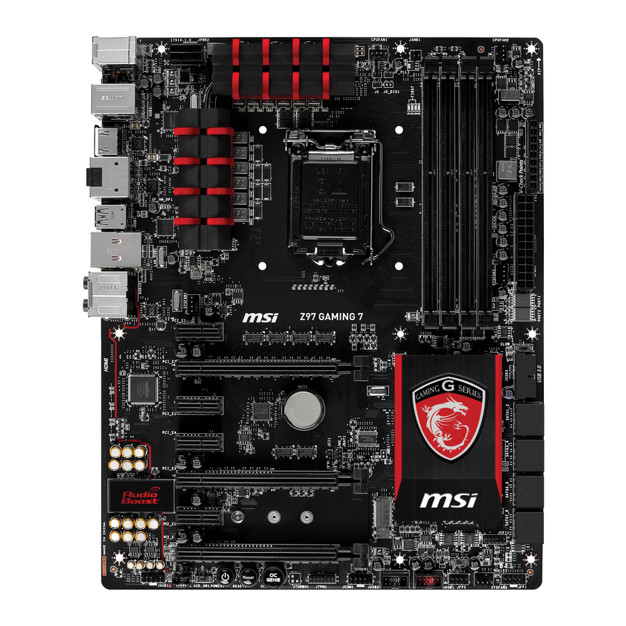
    Guide Rapide Des Connecteurs DIMM3 DIMM2 DIMM4 SYSFAN1 DIMM1 CPUFAN1 JPWR2 CPU Socket CPUFAN2 SYSFAN3 Panneau arrière JPWR1 PCI_E1 JCI1 SLOW_1 PCI_E2 JUSB3 PCI_E3 SATA1_2 JBAT1 PCI_E4 SATA3_4 PCI_E5 SATA5_6 PCI_E6 SATA7_8 M2_1 PCI_E7 BIOS_SW1 JFP1 SYSFAN2 JAUD1 JCOM1 JTPM1 JFP2 JUSB2 AUDPWR1...
  • Page 116: Guide Référence Des Connecteurs

    Guide référence des connecteurs Noms de ports Types des ports Page Panneau arrière Ports I/O Fr-7 AUD_SW1 Interrupteur Audio Power Fr-31 AUDPWR1 Connecteur Direct Audio Power Fr-23 BIOS_SW1 Interrupteur Multi-BIOS Fr-30 LGA1150 CPU Socket Fr-9 CPUFAN1~2,SYSFAN1~3 Connecteurs d'alimentation du ventilateur Fr-19 DIMM1~4 Emplacements de mémoire DDR3...
  • Page 117: Guide Rapide Du Panneau Arrière

    Guide rapide du panneau arrière S/PDIF-Out Port PS/2 optique Port USB 3.0 Combo clavier/ souris* Port LAN Ligne-In RS-Out Port USB 3.0 HDMI Ligne-Out CS-Out HDMI SS-Out Port USB 2.0* Bouton DisplayPort Port USB 3.0 d’effacement CMOS * Ports pour périphérique de jeux. ▶...
  • Page 118 ▶ S/PDIF-Out optique Ce connecteur S/PDIF (Sony et Philips Digital Interconnect Format) est utilisé pour la transmission audio numérique à des haut-parleurs externes via un câble optique. ® ▶ Port HDMI Le High-Definition Multimedia Interface est une interface audio/vidéo tout-numérique, qui est capable de transmettre des flux décompressés.
  • Page 119: Processeur : Cpu

    Processeur : CPU Introduction du LGA 1150 CPU A la surface du CPU LGA 1150 vous noterez deux encoches et un triangle jaune servant à aligner le CPU dans la bonne position sur la carte mère. Le triangle jaune corresponde à la Pin 1. Encoche Encoche Le triangle jaune corresponde à...
  • Page 120: Installation Du Cpu Et Son Ventilateur

    Installation du CPU et son ventilateur Quand vous installez un CPU, assurez-vous toujours que le CPU soit équipé d’un ventilateur, qui est nécessaire pour éviter la surchauffe et maintenir la stabilité. Suivez les instruction suivantes pour installer le CPU et son ventilateur correctement. Une installation incorrecte peut endommager votre CPU et la carte mère.
  • Page 121 3. Alignez les encoches et les clés d’alignement du socket. Abaissez le CPU en ligne droite, évitez de faire basculer ou glisser le CPU dans l’emplacement. Vérifiez qu'il est bien installé dans la bonne direction. 4. Fermez et glissez le plaque de charge sous le bouton de rétention. Fermez et engagez le levier de charge.
  • Page 122 7. Localisez le connecteur du ventilateur CPU sur la carte mère. 8. Placez le ventilateur sur la carte mère avec son câble face au connecteur du ventilateur. Les éléments de fixation doivent correspondre aux trous sur la carte. Connecteur de ventilateur CPU 9.
  • Page 123: Mémoire

    Mémoire Ces emplacements DIMM sont destinés à installer les modules de mémoire. DIMM1 DIMM2 DIMM3 DIMM4 Démonstration de vidéo Voir le vidéo sur l'installation des mémoires sur le site ci-dessous. http://youtu.be/76yLtJaKlCQ Règle de population en mode double canal En mode de double canal, les modules de mémoire peuvent transmettre et recevoir simultanément deux lignes de données.
  • Page 124: Trous Taraudés De Montage

    Trous Taraudés de Montage Avant d’installer votre carte mère, il faut d’abord installer les socles de montage néce saires sur le plateau de montage du boîtier de l’ordinateur. Si le boîtier de l’ordinateur est accompagné par un panneau Entrée/ Sortie arrière, veuillez le remplacer et utiliser celui qui est fournit dans la boîte de la carte.
  • Page 125: Connecteurs D'alimentation

    Connecteurs d’alimentation Démonstration de vidéo Voir le vidéo sur l’installation des connecteurs d’alimentation sur le site ci-dessous. http://youtu.be/gkDYyR_83I4 JPWR1~2 : Connecteur d'alimentation ATX Ce connecteur vous permet de relier une alimentation ATX. Pour cela, alignez le câble d’alimentation avec le connecteur et appuyez fermement le câble dans le connecteur. Si ceci est bien fait, la pince sur le câble d’alimentation doit être accrochée sur le connecteur d’alimentation de la carte mère.
  • Page 126: Emplacements D'extension

    Emplacements d’extension Cette carte mère contient de nombreux ports pour les cartes d’extension, tels que les cartes graphiques ou les cartes audio. PCI_E1~7 : Emplacement d’extension PCIe L'emplacement PCIe supporte l'interface de carte d'extension PCIe. Emplacement PCIe 3.0 x16 Emplacement PCIe 2.0 x1 Important Lorsque vous ajoutez ou retirez une carte d’extension, assurez-vous que le PC n’est pas relié...
  • Page 127: Cartes Vidéo/ Graphics

    Une ou plusieurs cartes vidéo ajoutées peuvent améliorer fortement la performance graphique du système. Pour une compatibilité parfaite, nous vous recommandons d’utiliser des cartes graphiques MSI. Démonstration de vidéo Voir le vidéo sur l’installation d’une carte graphique dans l’emplacement PCIe x16 avec verrou papillon sur le site ci-dessous.
  • Page 128: Connecteurs Internes

    Connecteurs internes SATA1~8 : Connecteurs SATA Ce connecteur est un port d’interface SATA haut débit. Chaque connecteur peut être relié à un appareil SATA. Les appareils SATA sont des disques durs (HDD), disque état solide (SSD), et lecteurs optiques (CD/ DVD/ Blu-Ray). Démonstration de vidéo Voir le vidéo sur l’installation d’un SATA HDD.
  • Page 129: Cpufan1~2,Sysfan1~3 : Connecteur D'alimentation Du Ventilateur

    CPUFAN1~2,SYSFAN1~3 : Connecteur d’alimentation du ventilateur Les connecteurs d’alimentation du ventilateur supportent les ventilateurs de type +12V. Si la carte mère est équipée d’un moniteur du matériel système intégré, vous devrez utiliser un ventilateur spécial pourvu d’un capteur de vitesse afin de contrôler le ventilateur de l’unité...
  • Page 130: Jfp1, Jfp2 : Connecteur Panneau Système

    JFP1, JFP2 : Connecteur panneau système Ces connecteurs se connectent aux interrupteurs et LEDs du panneau avant. Le JFP1 est conforme au guide de conception de la connectivité Entrée/sortie du panneau avant Intel . Lors de l’installation des connecteurs du panneau avant, veuillez utiliser ®...
  • Page 131: Jusb1~2 : Connecteurs D'extension Usb

    La SuperCharger Technology n’est pas disponible sur tous les modèles de carte • mère. Veuillez vous référer au site MSI pour vérifier si votre carte mère est équipé de la SuperCharger Technology. • Pour l’iPad, JUSB1 (marqué rouge) peut aussi charger l’iPad en état S3, S4, S5.
  • Page 132: Jusb3 : Connecteurs D'extension Usb

    JUSB3 : Connecteurs d’extension USB 3.0 Le port USB 3.0 est rétro-compatible avec les périphériques USB 2.0. Il supporte un taux de transfert jusqu’à 5 Gbit/s (Super-Vitesse). Important • Notez que les pins de VCC et GND doivent être branchées correctement afin d’éviter tout dommage possible.
  • Page 133: Jaud1 : Connecteur Audio Panneau Avant

    JAUD1 : Connecteur audio panneau avant Ce connecteur vous permet de connecter un audio sur le panneau avant.Il est conforme au guide de conception de la connectivité Entrée/sortie du panneau avant Intel ® AUDPWR1 : Connecteur Direct Audio Power Ce connecteur est utilisé pour alimenter directement les ports audio du panneau arrière.
  • Page 134: Jtpm1 : Connecteur De Module Tpm

    M2_1 : Port M.2 Le port M.2 supporte soit le module M.2 SATA 6Gb/s ou celui M.2 PCIe. Important Les ports SATA5 et SATA6 deviennent indisponibles lorsqu’un module est installé • dans le port M.2. • Intel RST ne supporte que les SSD M.2 PCIe avec ROM UEFI, les ROM Legacy ne sont pas supportées.
  • Page 135: Jcom1 : Connecteur De Port Sérial

    JCOM1 : Connecteur de port Sérial Le port serial est un port de communications de haute vitesse de 16550A, qui envoie/ reçoit 16 bytes FIFOs. Vous pouvez attacher un périphérique sérail. Fr-25...
  • Page 136: Point De Vérification Tension

    Point de vérification tension Ces points de vérification de tension servent à mesurer les tensions actuelles du système. Un multimètre est nécessaire (non fourni) pour vérifier les tensions. FV1 : Points de contrôle tension Ces points de vérification tension servent à mesurer les tensions du CPU et du PCH. Pour vérifier les tensions, il faut attacher le fil positif du multimètre à...
  • Page 137: Boutons

    à la section BIOS de ce manuel pour les instructions comment désactiver OC Genie dans le BIOS. • L’utilisation d’OC Genie est à la risque de l’utilisateur. Overclocking n’est jamais garanti par MSI. • Pour assurer un usage réussi d’OC Genie, les composants MSI sont recommandés. Fr-27...
  • Page 138: Power1 : Bouton D'alimentation

    POWER1 : Bouton d’alimentation Ce bouton sert à allumer ou éteindre le système. Appuyez sur ce bouton pour allumer ou éteindre le système. RESET1 : Bouton de réinitialisation Ce bouton sert à réinitialiser le système. Appuyez sur ce bouton pour le réinitialiser. Fr-28...
  • Page 139: Cavaliers

    Cavaliers JBAT1 : Cavalier d’effacement CMOS Il y a un CMOS RAM intégré, qui est alimenté par une batterie externe située sur la carte mère, destiné à conserver les données de configuration du système. Avec le CMOS RAM, le système peut lancer automatiquement le système d’exploitation chaque fois qu’il est allumé.
  • Page 140: Interrupteur

    BIOS endommagé avec les étapes ci-dessous. Préparation: 1. Préparez une clé USB bootable 2. Téléchargez la dernière version de BIOS depuis le site MSI official www.msi.com, et puis décompressez le fichier. 3. Copier AFUDE238.exe et le fichier BIOS sur la clé USB bootable.
  • Page 141: Slow_1 : Interrupteur De Démarrage Du Mode Ralenti

    SLOW_1 : Interrupteur de démarrage du mode ralenti Cet interrupteur est la solution de refroidissement LN2, fournissant les conditions extrêmes d'overclocking, à se démarrer à la fréquence stable du processeur et ainsi prévenir le crash du système. Normal Activé (Défaut) Important Les utilisateurs peuvent essayer l'overclocking à...
  • Page 142: Indicateurs D'état Led

    Indicateurs d'état LED Debug LED HDD LED BIOS B LED MSI LED BIOS A LED Tableau d'état LED Le tableau suivant décrit l'état d'indicateurs LED. Etat LED Description Allumé Debug Clignote Activité disque dur BIOS A LED Bleu BIOS A en opération...
  • Page 143 Tableau LED Debug Code Veuillez vous référer au tableau suivant pour plus d'information sur le message LED du code Debug. Poste Etat 02,07 Allumage initialisation CPU 03,08 Allumage initialisation North Bridge 04,09 Allumage initialisation South Bridge Allumage initialisation Cache 11~14,32~36,56~5A Antérieur initialisation CPU 15~18,37~3A Antérieur initialisation North Bridge...
  • Page 144: Pilotes Et Utilitaires

    Veuillez suivre les étapes suivantes pour installer les pilotes et les utilitaires pour votre ordinateur neuf. Insérez le disque de pilote MSI dans le lecteur optique. L'écran de réglages apparaît automatiquement si l'autorun est activé dans le système d'exploitation. Cliquez sur Total Installer. Une boite de dialogue surgit et affiche tous les pilotes necessaires.
  • Page 145: Configuration Bios

    Configuration BIOS CLICK BIOS est développé par MSI qui fournit une interface graphique utilisateur pour régler les paramètres du BIOS a l'aide de la souris et du clavier. Avec CLICK BIOS, vous pouvez modifier les réglages BIOS, surveiller la température du CPU, choisir la priorité...
  • Page 146: Vue D'ensemble

    Vue d'ensemble Entrer dans le BIOS, l'écran suivant apparaît. Indicateur température Favori Langue Information du système Barre priorité de périphérique Bouton virtuel démarrage OC Genie Sélection du Sélection du menu BIOS menu BIOS Ecran de menu ▶ Sélection du menu BIOS Les options suivantes sont disponibles : ■...
  • Page 147 Activer ou désactiver la fonction OC Genie en cliquant sur ce bouton. Lorsqu’il est activé, le bouton s’allume. Activer la fonction OC Genie peut automatiquement overclocker avec le profil d’overclocking optimisé MSI. Important Il est conseillé de ne faire aucune modification au menu OC ni de charger les valeurs par défaut après l'activation de la fonction OC Genie.
  • Page 148 Opération Vous pouvez contrôler le réglage BIOS avec la souris et le clavier. La liste ci-dessous décrit les opérations des touches raccourcis et de la souris. Touches Souris Description <↑↓→← > Choisir un article Choisir un champ <Enter> Choisir une icône/ un domaine Cliquer/ Double-cliquer le bouton gauche <Esc>...
  • Page 149 OC Menu Ce menu est destiné aux utilisateur avancés souhaitant overclocker la carte mère. Important • L’Overclocking manuel du PC n’est recommandé que pour les utilisateurs avancés. • L’Overclocking n’est pas garanti, et une mauvaise manipulation peut invalider votre garantie et endommager sévèrement votre matériel. •...
  • Page 150 Active la fonction OC Genie via le bouton virtuel dans le BIOS ou le bouton physique sur la carte mère. L’activation de la fonction OC Genie peut overclocker automatiquement le système avec le profil d’overclocking MSI optimisé. [By BIOS Options] La fonction OC Genie est activée en cliquant le bouton virtuel OC Genie en haut à...
  • Page 151 < Réglages DRAM > ▶ DRAM Frequency [Auto] Définit la fréquence DRAM. Veuillez noter que le comportement d'overclocking n'est pas garanti. ▶ Adjusted DRAM Frequency Montre la fréquence ajustée DRAM. En lecture seule. ▶ Extreme Memory Profile (X.M.P) [Disabled] X.M.P. (Extreme Memory Profile) est la technologie d’overclocking par le module de mémoire.
  • Page 152 ▶ Memory Fast Boot [Auto] Active ou désactive l'initialisation et le test de la mémoire à chaque démarrage. [Auto] Ce réglage est automatiquement configuré par le BIOS. [Enabled] La mémoire imitera complètement l'archive de la première initiation et la première formation. La mémoire n'est ensuite plus initialisée ni testée au moment du démarrage, de façon à...
  • Page 153 ▶ CPU Switching Frequency [Auto] Définit la vitesse de fonction du PWM pour stabiliser la tension du cœur CPU et minimiser minimize la gamme d'ondulation. L'augmentation de la vitesse de fonction PWM élève la température MOSFET. Il est nécessaire alors de disposer d'une solution de refroidissement adéquate pour MOSFET avant d'augmenter cette valeur.
  • Page 154 ▶ CPU Core/ Ring/ GT Voltage Offset Mode [Auto]* Choisit le mode de compensation pour la tension du cœur CPU/ Ring/ GT. Ce menu apparâit lorsque “CPU Core/Ring/GT Voltage Mode” est mis en [Offset Mode]/ [Adaptive + Offset]/ [Override + Offset]. [Auto] Ce réglage est configuré...
  • Page 155 ▶ CPU Specifications Appuyez sur <Enter> pour entrer dans le sous-menu. Ce sous-menu affiche l’information du CPU installé. Vous pouvez également accéder au menu d’information à tout temps en appuyant sur [F4]. En lecture seule. ▶ CPU Technology Support Appuyez sur <Enter> pour entrer dans le sous-menu. Ce sous-menu affiche les principales fonctions prises en charge par le CPU installé.
  • Page 156 ▶ Intel Virtualization Tech [Enabled] Active ou désactive la technologie Intel Virtualization. [Enabled] Active la technologie Intel Virtualization et autoriser une plate-forme visant à faire fonctionner plusieurs systèmes d'exploitation dans des partitions indépendentes. Le système peut fonctionner virtuellement comme des systèmes multiples. [Disabled] Désactive cette fonction.
  • Page 157 ▶ Package C State limit [Auto] Ce menu permet de choisir un mode C-state de CPU pour économiser l’énergie lorsque le système est au repos. Ce menu apparaît lorsque "Intel C-State" est activé. [Auto] Ce réglage est configuré automatiquement par le BIOS. [C0~C7s] Le niveau d'économie d'énergie du plus élevé...
  • Page 158 ▶ Internal VR OVP OCP Protection [Auto] Active ou désactive la protection sur tension et la protection sur-courant pour VR (Voltage Regulator) du CPU. [Auto] Ce réglage est configuré automatiquement par le BIOS. [Enabled] Définit la limite de tension sur le VR interne du CPU pour la protection sur-tension et la protection sur-courant.
  • Page 159: Русский

    Русский Благодарим вас за авбор системной платы серии Z97 GAMING 7 (MS-7916 v1.X) ATX. Материнские платы серии Z97 GAMING 7 на бвзе чипсета Intel Z97 и обеспечивают оптимальную производительность ® системы. Платы серии Z97 GAMING 7, обеспечивают высокую производительность и являются профессиональными платформами для...
  • Page 160: Характеристики Материнской Платы

    6x портов USB 2.0 (2 порта на задней панели, 4 порта доступны через внутренние USB 2.0 разъемы*) ■ Чипсет ASMedia ASM1074 4x порта USB 3.0 на задней панели ■ Чипсет ASMedia ASM1042 2x порта USB 3.0 на задней панели * Внутренний JUSB1 разъем поддерживает MSI Super Charger. Ru-2...
  • Page 161 Аудио ■ Realtek ALC1150 Codec ® 7.1-канальный High Definition Audio Поддержка выход S/PDIF ■ 1x Killer E2205 Гигабитный Сетевой контроллер* * Сетевой менеджер Killer применяется только для Windows 7 и Windows 8/ 8.1 в настоящее время. Драйверы для других операционных систем будут доступны на...
  • Page 162 XSplit Gamecaster ■ Killer Network Manager Форм-фактор ■ ■ 12 дюймов x 9.6 дюймов (30.5 см x 24.4 см) Последние сведения о поддержке процессора можно получить по адресу http://www.msi.com/cpu-support/ Дополнительные сведения о совместимых компонентах можно получить по адресу http://www.msi.com/test-report/ Ru-4...
  • Page 163: Краткое Руководство По Разъемам

    Краткое руководство по разъемам DIMM3 DIMM2 DIMM4 SYSFAN1 DIMM1 CPUFAN1 JPWR2 CPU Socket CPUFAN2 SYSFAN3 Задняя панель JPWR1 PCI_E1 JCI1 SLOW_1 PCI_E2 JUSB3 PCI_E3 SATA1_2 JBAT1 PCI_E4 SATA3_4 PCI_E5 SATA5_6 PCI_E6 SATA7_8 M2_1 PCI_E7 BIOS_SW1 JFP1 SYSFAN2 JAUD1 JCOM1 JTPM1 JFP2 JUSB2 AUDPWR1...
  • Page 164: Справочное Руководство По Разъемам

    Справочное руководство по разъемам Наименование порта Тип порта Страница Разъемы на задней панели Порты ввода / вывода Ru-7 AUD_SW1 Переключатель питания Audio Ru-31 AUDPWR1 Коннектор прямого питания Audio Ru-23 BIOS_SW1 Переключатель Multi-BIOS Ru-30 Разъем LGA1150 CPU Ru-9 CPUFAN1~2,SYSFAN1~3 Разъемы питания вентиляторов Ru-19 DIMM1~4 Слоты...
  • Page 165: Краткое Руководство По Работе С Задней Панелью

    Краткое руководство по работе с задней панелью Оптический комбинированный Порт USB 3.0 Выход S/PDIF порт PS/2 клавиатуры/мыши* Порт LAN RS-Выход Линейный Порт USB 3.0 вход HDMI Линейный CS-Выход выход HDMI SS-Выход Микрофон DisplayPort Порт USB 2.0* Кнопка очистки Порт USB 3.0 CMOS * Порт...
  • Page 166 ▶ Оптический выход S/PDIF Разъем S/PDIF (цифровой интерфейс Sony/Philips) предназначен для передачи цифрового аудио на внешние громкоговорители через оптоволоконный кабель. ® ▶ Порт HDMI Мультимедийный интерфейс высокой четкости (HDMI) представляет собой полностью цифровой аудио- видеоинтерфейс, позволяющий передавать несжатые потоки данных. Интерфейс HDMI обеспечивает передачу ТВ-сигнала по...
  • Page 167: Цп (Центральный Процессор)

    выполнением разгона системы убедитесь в том, что все компоненты системы смогут выдержать разгон. Производитель не рекомендует использовать параметры, выходящие за пределы технических характеристик устройств. Гарантия MSI не распространяется на повреждения и другие возможные последствия ненадлежащей эксплуатации и несоблюдения технических характеристик изделия.
  • Page 168 Установка ЦП и радиатора При установке процессоора обязательно установите радиатор ЦП.Радиатор ЦП предупреждает перегревание и обеспечивает стабильность работы системы. Ниже представлены инструкции по правильной установке процессора и радиатора ЦП. Неправильная установка приводит к выходу из строя процессора и материнской платы. Видео...
  • Page 169 3. Совместите выемки на процессоре с ключами совмещения на сокете. Опустите процессор вниз без наклона. Движение процессора в сокете недопустимо. Проверьте надежность установки процессора в сокете. 4. Закройте и сдвиньте прижимную пластину под ручку удержания. Закройте и зацепите рычаг фиксации. Выемки...
  • Page 170 7. Найдите разъем для подключения вентилятора ЦП на материнской плате. 8. Установите кулер на материнскую плату, направив его кабель в сторону разъема для подключения вентилятора. Разъем подключения вентилятора 9. Нажмите на радиатор сверху так, чтобы закрепить четыре защелки в отверстиях на материнской плате. Нажмите на защелки для закрепления вентилятора.
  • Page 171: Память

    Память Разъемы DIMM предназначены для установки модулей памяти. DIMM1 DIMM2 DIMM3 DIMM4 Видео Демонстрация Смотрите видео,чтобы узнать как установить память по указанному адресу. http://youtu.be/76yLtJaKlCQ Правила заполнения гнезд при использовании двухканального режима Dual-Channel В двухканальном режиме модули памяти могут одновременно передавать и получать...
  • Page 172: Отверстия Под Установочные Винты

    Отверстия под установочные винты Для установки материнской платы на монтажной плате системного блока сначала установите необходимые установочные стойки. Если в комплект поставки системного блока входит задняя панель ввода-вывода, замените ее задней панелью ввода-вывода, которая поставляется с материнской платой. Задняя панель ввода-вывода без труда устанавливается в системном блоке...
  • Page 173: Электропитание

    Электропитание Видео Демонстрация Смотрите видео,чтобы узнать как установить разъем питания. http://youtu.be/gkDYyR_83I4 JPWR1~2: Разъемы питания ATX Эти разъемы предназначены для подключения разъема питания ATX. Для подключения ATX разъема питания совместите кабель питания с разъемом и прочно закрепите его. При правильном выполнении подключения защелка на кабеле...
  • Page 174: Pci_E1~7: Слоты Расширения Pcie

    Слоты расширения Данная материнская плата содержит множество разъемов для установки плат расширения, в частности, дискретных видеокарт или звуковых карт. PCI_E1~7: Слоты Расширения PCIe Слот PCIe поддерживает платы расширения с интерфейсом PCIe. PCIe 3.0 x16 слот PCIe 2.0 x1 слот Внимание Перед...
  • Page 175: Видео/ Установка Дискретной Видеокарты

    в CPU, но Вы так же можете значительно повысит графическую производительность системы, путем добавление одной или нескольких дискретных видеокарт в слоты расширения. Для лучшей совместимости рекомендуется использовать графические карты MSI. Видео Демонстрация Смотрите видео,чтобы узнать как установить видеокарту на слоте...
  • Page 176: Внутренние Разъемы

    Внутренние разъемы SATA1~8: Разъемы SATA Данный разъем является высокоскоростным интерфейсом SATA. К любому разъему SATA можно подключить одно устройство SATA. К устройствам SATA относятся жесткие диски, твердотельные накопители и накопители на оптических дисках (компакт-диски/ DVD-диски/ Blu-Ray-диски). Видео Демонстрация Смотрите видео,чтобы узнать как установить SATA жесткие...
  • Page 177 CPUFAN1~2,SYSFAN1~3: Разъемы питания вентиляторов Разъемы питания вентиляторов поддерживают вентиляторы с питанием +12 В. Если на системной плате установлена микросхема аппаратного мониторинга, необходимо использовать специальные вентиляторы с датчиками скорости для использования функции управления вентиляторами. Обязательно подключите все системные вентиляторы. Некоторые системные вентиляторы невозможно подключить...
  • Page 178 JFP1, JFP2: Разъемы панели системы Эти разъемы служат для подключения кнопок и светодиодных индикаторов, расположенных на передней панели. Разъем JFP1 соответствует стандартам Intel Front Panel I/O Connectivity Design. При установке разъемов передней ® панели для удобства используются переходники и кабели, входящие в комплект поставки.
  • Page 179 плееры, принтеры, модемы и т. д. Разъем JUSB1 (красный значок) поддерживает новую технологию SuperCharger от компании MSI, которая обеспечивает ускоренную зарядку сотового телефона или другого устройства, подключаемого к разъему USB. Для активации этой функции установите приложение MSI SuperCharger в свой компьютер. При...
  • Page 180: Jci1: Разъем Датчика Открытия Корпуса

    JUSB3: Разъем расширения USB 3.0 Порт USB 3.0 обратно совместим с устройствами USB 2.0. Он поддерживает скорость передачи данных до 5 Гбит/с(SuperSpeed). Внимание • Помните, что во избежание повреждений необходимо правильно подключать контакты VCC и GND. • Для использования устройства USB 3.0 подключитесь к разъему USB 3.0 с помощью...
  • Page 181 JAUD1: Аудиоразъем на передней панели Этот разъем служит для подключения аудиоразъема на передней панели системного блока. Этот разъем соответствует стандарту Intel Front Panel I/O ® Connectivity Design. AUDPWR1: Коннектор прямого питания Audio Данный коннектор обеспечивает прямое питание аудио портов задней панели. Прямое...
  • Page 182: Jtpm1: Разъем Модуля Трм

    M2_1: Порт M.2 Порт M.2 поддерживает как модули M.2 SATA 6Гб/с, так и модули M.2 PCIe. Внимание Порты SATA5 и SATA6 будут недоступны при установке модуля в порт M.2. • • Intel RST поддерживает PCIe M.2 SSD только с UEFI ROM. При наличии Legacy ROM, поддержка...
  • Page 183: Jcom1: Разъем Последовательного Порта

    JCOM1: Разъем последовательного порта Данный разъем является высокоскоростным последовательным портом передачи данных 16550А с 16-разрядной передачей FIFO. К этому разъему можно подключить устройство c последовательным интерфейсом. Ru-25...
  • Page 184: Замер Напряжения

    Замер напряжения Данные разъемы для замера напряжения используется для измерения текущих значений напряжения в системе. Для замера напряжения потребуется мультиметр (приобретаемый отдельно). FV1: Разъем для замера напряжения Для замера напряжения используются дополнительные кабели для замера напряжения, входящие в комплект поставки материнской платы. Прикрепите положительный...
  • Page 185: Кнопки

    отключению функции OC Genie из BIOS представлены в разделе BIOS руководства пользователя. Ответственность за применение функции OC Genie и его последствия несет • пользователь. Компания MSI никогда не гарантирует успешность и результаты «разгона» системы. • Для успешной работы функции OC Genie рекомендуется использовать...
  • Page 186 POWER1: Кнопка питания Эта кнопка предназначена для включения и выключения системы. Нажмите на кнопку один раз для включения или выключения системы. RESET1: Кнопка перезагрузки Эта кнопка предназначена для перезагрузки системы. Нажмите на нее для сброса системы. Ru-28...
  • Page 187: Джампер

    Джампер JBAT1: Джампер очистки данных CMOS На плате установлена CMOS память с питанием от батарейки для хранения данных о конфигурации системы. С помощью памяти CMOS операционная система (ОС) автоматически загружается каждый раз при включении. Для сброса конфигурации системы (очистки данных CMOS памяти), воспользуйтесь этой перемычкой.
  • Page 188: Переключатели

    неполная прошивка) и система не загружается, Вы можете восстановить BIOS следуя инструкции ниже. Подготовительные действия: 1. Подготовьте загрузочную USB флэшку. 2. Скачайте архив с последним BIOS с официального сайта MSI www.msi.com, и разархивируйте его. 3. Скопируйте AFUDE238.exe и файл BIOS на загрузочную USB флэшку. Восстановление BIOS с помощью M-Flash: 1.
  • Page 189: Slow_1: Переключатель Режима Медленной Загрузки

    SLOW_1: Переключатель режима медленной загрузки Этот переключатель используется в случае применения систем охлаждения LN2, что в свою очередь позволяет создать экстремальные условия для оверклокинга. Это по позволяет загружаться при стабильной частоте процессора и предотвращает сбой в работе. Нормальное Включено (По умолчанию) Внимание...
  • Page 190: Световые Индикаторы

    Световые индикаторы Debug LED HDD LED BIOS B LED MSI LED BIOS A LED Таблица состояния индикатора В следующей таблице описаны состояния светодиодных индикаторов. Состояние Индикатор Описание индикатора Вкл. Загрузка Микает Активиация жесткого диска BIOS A LED Синий BIOS A в эксплуатации...
  • Page 191 Таблица кодов индикатора загрузки Коды индикатора загрузки (Debug LED) перечислены в таблице ниже. Код Состояние 02,07 Включение питания Инициализация процессора 03,08 Включение питания Инициализация Северного моста 04,09 Включение питания Инициализация Южного моста Включение питания Инициализация кэша 11~14,32~36,56~5A Предварительная инициализация процессора 15~18,37~3A Предварительная...
  • Page 192: Драйверы И Утилиты

    Установка драйверы и утилит Для установки драйверов и утилит на своем компьютере следуйте приведенным ниже указаниям. Вставьте диск с драйверами MSI Driver Disc в привод для оптических дисков. Если в операционной системе включена функция автозапуска, автоматически отобразится утилита installer. Утилита Installer автоматически найдет и перечислить все необходимые...
  • Page 193: Настройка Bios

    одновременно нажав клавиши <Ctrl>+<Alt>+<Delete>. MSI также дополнительно предоставляет два метода для входа в настройки BIOS. Вы можете нажать “GO2BIOS” на экране в утилите “MSI Fast Boot” или нажать физическую кнопку “GO2BIOS" (опционально) на материнской плате для непосредственно входа в настройки BIOS при следующей загрузке.
  • Page 194: Общие Сведения

    Общие Сведения После входа в BIOS отображается следующий экран. Мониторинг температур Избранное Язык Системная Информация Приоритет загрузочных Кнопка устройств Virtual OC Genien Выбор Выбор меню BIOS меню BIOS Экран просмотра раздела ▶ Выбор меню BIOS Доступны следующие опции: ■ SETTINGS - В данном меню указывают параметры настройки для микро- процессора, загрузочного...
  • Page 195 Кнопка Virtual OC Genie Включает или выключает функции OC Genie, при нажатии кнопки. Данная кнопка мигает при включении. Включение функции OC Genie приводит к автоматическому разгону с оптимизированным профилем MSI. Внимание Мы рекомендуем не делать никаких изменений в меню OC и не загружать...
  • Page 196 Работа Вы можете управлять параметрами настройки BIOS с помощью мыши и клавиатуры. В нижеследующей таблице представлен перечень и описание «клавиш быстрого вызова» и функций мыши. Клавиша Mыши Описание быстрого вызова <↑↓→← > Выбор элемента Перемещение указателя <Enter> Выбор значка/ поля Щелчок/ Двойной...
  • Page 197 Меню OC Данное меню предназначено для опытных пользователей и предоставляет возможности для "разгона" системы. Внимание Разгонять ПК вручную рекомендуется только опытным пользователям. • • Производитель не гарантирует успешность разгона. Неправильное выполнение разгона может привести к аннулированию гарантии и серьезному повреждению оборудования. •...
  • Page 198 Для включения функции OC Genie нажмите виртуальную кнопку в BIOS или физическую кнопку на материнской плате. Включение функции OC Genie позволяет автоматически разгонять систему с оптимизированным профилем разгона MSI. [By BIOS Options] Для включения функции OC Genie нажмите на виртуальную...
  • Page 199 ▶ CPU Base Clock Apply Mode [Auto]* Устанавливает способ применения изменений для корректировки базовой частоты ЦП. [Auto] Этот параметр будет настроен автоматически с помощью BIOS. [Next Boot] Процессор перейдет на скорректированную базовую частоту ЦП при следующей загрузке. [Immediate] Процессор перейдет на скорректированную базовую частоту ЦП немедленно.
  • Page 200 ▶ DRAM Training Configuration* Нажмите <Enter> для входа в подменю. Включает или выключает различные способы тренировки DRAM. Система может работать нестабильно или не загружается после изменения настроек в этом подменю. Если это происходит, очистите данные CMOS и восстановите настройки по умолчанию. (см. перемычка...
  • Page 201 ▶ CPU Over Voltage Protection [Auto] Устанавливает верхнюю границу максимального напряжения для защиты процессора от слишком высокого напряжения. Если установлено "Auto", BIOS автоматически настроит этот параметр. Чем выше значение тем ниже степень защиты и выше вероятность выхода системы из строя. ▶...
  • Page 202 ▶ CPU Core/Ring/GT Voltage Mode [Auto]* Позволяет выбрать режим управления напряжениями ядра процессора/ шины Ring/ GT. [Auto] Этот параметр будет настроен автоматически с помощью BIOS. [Adaptive Mode] Устанавливает адаптивное напряжение автоматически для оптимальной производительности системы. [Override Mode] Позволяет устанавливать напряжения вручную. [Offset Mode] Позволяет...
  • Page 203 ▶ CPU SA/ IO Analog/ IO Digital Voltage Offset Mode [Auto]* Выбор режима смещения для напряжения CPU SA/ IO Analog/ IO Digital. Этот пункт появляется, когда "CPU SA/IOA/IOD Voltage Mode" установлено в [Offset Mode]. [Auto] Этот параметр будет настроен автоматически с помощью BIOS. Позволяет...
  • Page 204 ▶ CPU Features Нажмите <Enter> для входа в подменюс. ▶ Hyper-Threading Technology [Enabled] Процессор использует технологию Hyper-threading для увеличения производительности. Технология Intel Hyper-Threading позволяет наскольким наборам регистров в процессоре исполнять инструкции одновременно. Это существенно увеличивает производительность системы. Этот пункт появляется, когда установленный процессор поддерживает изменение данного...
  • Page 205 ▶ Adjacent Cache Line Prefetch [Enabled] Включение или выключение предвыборки процессора (MLC Spatial prefetcher). [Enabled] Включение соседней предвыборки линии кэша для сокращения времени задержки кэша и настройки производительности для конкретного использования. [Disabled] Выключает запрашиваемую линию кэша. ▶ CPU AES Instructions [Enabled] Включение...
  • Page 206 ▶ EIST [Enabled] Включение или выключение технологии Enhanced Intel SpeedStep. Этот пункт ® появится, когда “Simple/ Advanced Mode” установлено в [Simple]. [Enabled] Включение EIST для регулировки напряжения и частоты ядра процессора. Этот пункт может снизить среднее энергопотребление и тепло. [Disabled] Выключение...
  • Page 207: Installation/Установка

    Installation/ Установка This chapter provides demonstration diagrams about how to install your computer. Some of the installations also provide video demonstrations. Please link to the URL to watch it with the web browser on your phone or tablet. You may have even link to the URL by scanning the QR code. Das vorliegende Kapitel bietet die Demo-Diagrammen, wie Sie Ihren Computer zu installieren.
  • Page 208: Cpu

    http://youtu.be/bf5La099urI...
  • Page 210: Memory/ Speicher/ Mémoire/ Памяти

    Memory/ Speicher/ Mémoire/ Памяти http://youtu.be/76yLtJaKlCQ...
  • Page 211: Motherboard/ Carte Mère/ Материнские Платы

    Motherboard/ Carte mère/ Материнские платы...
  • Page 213 Power Connector/ ATX-Stromanshcluss/ Connecteurs d'alimentation/ Pазъема питания http://youtu.be/gkDYyR_83I4 oder или...
  • Page 215: Sata Hdd

    SATA HDD http://youtu.be/RZsMpqxythc oder или oder или...
  • Page 216 4.2 cm 6 cm 8 cm A-10...
  • Page 217: Pазъемов Передней Панели

    Front Panel Connector/ Frontpanel Anschluss/ Connecteur panneau avant/ Pазъемов передней панели JFP1 http://youtu.be/DPELIdVNZUI JAUD1 A-11...
  • Page 218: Peripheral Connector/ Peripheriestecker/Connecteur Périphérique/ Периферийных Разъемов

    Peripheral Connector/ Peripheriestecker/ Connecteur périphérique/ Периферийных разъемов USB2.0 oder или USB3.0 A-12...
  • Page 219: Graphics Card/ Grafikkarte/ Carte Graphique/Bидеокарты

    Graphics Card/ Grafikkarte/ Carte graphique/ Bидеокарты http://youtu.be/mG0GZpr9w_A A-13...
  • Page 220 A-14...

Table des Matières