Table des Matières
Publicité
Les langues disponibles
Les langues disponibles
Liens rapides
Publicité
Chapitres
Table des Matières

Manuels Connexes pour Futurelight Scan H - 150


Sommaire des Matières pour Futurelight Scan H - 150
- Page 1 BEDIENUNGSANLEITUNG USER MANUAL MODE D’EMPLOI © Copyright Für weiteren Gebrauch aufbewahren ! Keep this manual for future needs ! Nachdruck verboten ! Gardez ce mode d’emploi pour des Reproduction prohibited ! utilisations ultérieures ! Réproduction interdit !
- Page 2 FUTURELIGHT SC-980 für HMI 1200 W ........51832325 FUTURELIGHT SCAN H-150 für EFR-Lampe 150W ....51832330 FUTURELIGHT DP H250 für 24 V/250 W G-6,35 ......51832340 FUTURELIGHT DP 200 für MSD 200 W Lampe ......51832342 FUTURELIGHT DV 200 für MSD 200 W Lampe ......51832344 FUTURELIGHT DOMINATOR MKII DMX HMI 1200 ....
-
Page 3: Table Des Matières
Inhaltsverzeichnis 1. Sicherheit ........................4 1.1 Sicherheitshinweise ....................4 1.2 Bestimmungsgemäße Verwendung ................4 2. Allgemeines ........................5 2.1 Beschreibung der Teile....................5 2.2 Einsetzen der Lampe ....................5 3. Installation ........................6 3.1 Allgemeine Hinweise ....................6 3.2 Anschluß ans Netz ...................... 6 3.3. -
Page 4: Sicherheit
Lassen Sie das Gerät nicht von Personen bedienen, die sich nicht mit dem Gerät auskennen. Wenn Geräte nicht mehr korrekt funktionieren, ist das meist das Ergebnis von unfachmännischer Bedienung ! Achtung: Wird der FUTURELIGHT HC-Controller verwendet, muß beim Master-Gerät unbedingt ein 6,35mm- Stereo-Klinkenstecker in die DMX IN-Eingangsbuchse gesteckt werden! Betreiben Sie das Gerät nur, nachdem Sie sich vergewissert haben, daß... -
Page 5: Allgemeines
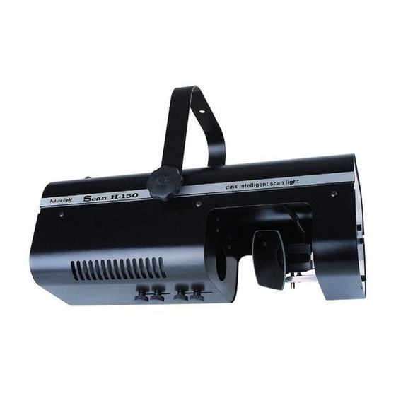
2. Allgemeines 2.1 Beschreibung der Teile 1 - Bügel 7 - Sicherungshalter 2 - Spiegel 8 - Netzanschluß 3 - Gehäuseschrauben 9 - DMX Ausgang 4 - Lufter 10 - DMX Eingang 5 - Feststellschraube 11 - DIP Schalter zur Projektorwahl 6 - Sub-D-Buchse für HC-Controller 12 - Betriebsanzeige 2.2 Einsetzen der Lampe... -
Page 6: Installation
Gobo-Farbrad Setzen Sie nun die Lampe ein. Vermeiden Sie es, den Glaskörper mit bloßen Händen zu berühren. Beachten Sie auch unbedingt die Hinweise des Lampenherstellers Vergewissern Sie sich, daß die Lampe auch richtig fest in der Fassung sitzt. Schließen Sie das Gehäuse wieder, und ziehen Sie die Gehäuseschrauben fest an. -
Page 7: Anschluß Des Hc-Controllers
Stecken Sie den HC-Controller in die Sub-D-Buchse (15) ein, und folgen Sie den Anweisungen in der Bedienungsanleitung des HC-Controllers. Achtung: Wird der FUTURELIGHT HC-Controller verwendet, muß beim Master-Gerät unbedingt ein 6,35mm- Stereo-Klinkenstecker in die DMX IN-Eingangsbuchse gesteckt werden! 4. Bedienung 4.1 Funktionen der Steuerkanäle... -
Page 8: Kodierung Des Projektors
III. Steuerkanal 3 - Lüfter: 0-127 Lüfter auf 100% 128-255 Lüfter auf 80% IV. Steuerkanal 4 - Gobo-/Farbrad 0 - 7 Black-Out 128-135 Gobo 11: Multi-Colour 1 8 -15 Gobo 1: weiß 136-143 Gobo 12: Multi-Colour 2 16 - 23 Gobo 2: blau 144-151 Strobe Gobo 1... -
Page 9: Wartung Und Reinigung
Elektronik - Digitaler Serieneingang DMX 512 - 4 Steuerkanäle: Kanal 1: Horizontale Spiegelbewegung Kanal 2: Vertikale Spiegelbewegung Kanal 3: Lüfter Kanal 4: Gobo-/Farbrad Gehäuse - Durch die große Gehäuseöffnung einfacher Zugriff zur Lampe und zu den wichtigsten Teilen Abmessungen und Gewicht - L x B x H: 435 x 162 x 162mm (ohne Bügel) - L x B x H: 435 x 230 x 300mm (mit Bügel) - Gewicht: 6,8kg... - Page 10 Table of contents 1. Introduction ........................11 1.1 Safety instructions ....................11 1.2 Operating instructions ....................11 2. In general ........................12 2.1 Description of components ..................12 2. 2 Fitting the lamp......................12 3. Installation ........................13 3.1 General instructions ....................13 3.2 Connection to the mains ...................
-
Page 11: Introduction
With a voltage of 230 V you can suffer a dangerous electric shock when touching the wires ! 1. Introduction Thank you for having chosen a FUTURELIGHT SCAN H-150. You will see you have acquired a powerful and versatile device. Unpack your SCAN H-150. -
Page 12: In General
2. In general 2.1 Description of components 7 - Fuseholder 1 - Bracket 8 - Mains plug 2 - Mirror 9 - DMX Output 3 - Fastening screws 10 - DMX Input 4 - Cooling fan 11 - DIP switches for projector selection 5 - Screws for bracket 12 - Operating LED 6 - Sub-D-jack for HC-Controller... -
Page 13: Installation
Gobo-Colourwheel During the installation do not touch the glass-bulbs bare- handed! Please follow the lamp manufacturer’s notes! Before you close the housing again, make sure that the lamp is installed tightly into the lampholder system. Reclose the housing and tighten the fastenig screws. Lampholder Switch on the device with closed housing only! 3. -
Page 14: Connection To The Hc-Controller
Plug the HC-Controller in the Sub-D-jack (15) and follow the instructions given in the controller’s user manual. Caution: If the FUTURELIGHT HC-controller is to be used, it is absolutely necessary to plug a 6.35mm-stereo- Jack plug in the DMX IN jack of the master-device. -
Page 15: Projector Addressing (For Digital Signals)
4.2 Projector addressing (for digital signals) DIP switch settings Projector No. & Channels Projector 1 - Channels 1-4 Projector 2 - Channels 5-8 Projector 3 - Channels 9-12 Projector 4 - Channels 13-16 Each projector occupies 4 channels. To ensure that the control signals are properly directed to each projector, the projector requires adressing. -
Page 16: Maintenance And Cleaning
6. Maintenance and cleaning It is absolutely essential that the projector is kept clean and that dust, dirt and smoke fluid residues must not build up on or within the projector. If this happens, the light output from the projector will be significantly reduced. Regular cleaning will not only ensure the maximum light output, but will also allow the projector to function reliably throughout its life. - Page 17 Sommaire 1. Sécurité ........................18 1.1 Instructions de sécurité ..................... 18 1.2 Emploi selon les prescriptions .................. 18 2. En général ........................19 2.1. Déscription des éléments ..................19 2.2. Installation de l’ampoule ..................19 3. Installation ........................20 3.1. Indications générales ....................20 3.2.
-
Page 18: Sécurité
La plupart des pannes survenant sur cet appareil sont dues à une utilisation inappropriée par des personnes incompétentes. Attention: Si vous utilisez le FUTURELIGHT contrôleur HC, il et absolument nécéssaire de ficher un Jack 6,35 à l’entrée DMX II de l’appareil master. -
Page 19: En Général
2. En général 2.1. Déscription des éléments 7 - Porte-fusible 1 - Ceintre de fixation 8 - Câble d’alimentation 2 - Miroir 9 - Sortie DMX 3 - Vis de boîtier 10 - Entrée DMX 4 - Ventilateur 11 - Interrupteurs DIP pour le choix du projecteur 5 - Vis de fixation pour le ceintre 12 - Indicateur de l’operation 6 - Douille Sub-D pour le contrôleur HC... -
Page 20: Installation
Roue des gobos/couleurs verre directement avec les doigts. Respectez les consignes du constructeur. Assurez vous que la lampe soit bien placée dans la douille. Refermer le couvercle et serrer bien les vis de boîtier. Douille d’ampoule Ne jamais mettre l’appareil sous tension sans que le boîtier ne soit pas refermé. 3. -
Page 21: Connexion Au Contrôleur Hc
Connectez le contrôleur HC à la douille Sub-D (15) et suivez les instructions dans le mode d’emploi du contrôleur. Attention: Si vous utilisez le FUTURELIGHT contrôleur HC, il et absolument nécéssaire de ficher un Jack 6,35 à l’entrée DMX II de l’appareil master. -
Page 22: Codage Du Projecteur
4.2. Codage du projecteur Tableau de codage: Numéro du projecteur & canaux Projecteur 1 - canaux 1-4 Projecteur 2 - canaux 5-8 Projecteur 3 - canaux 9-12 Projecteur 4 - canaux 13-16 Chaque projecteur a 4 canals de contrôle. Pour que les signals de commande s’adressent correctement à chaque projecteur, les projecteurs doivent être codés. -
Page 23: Entretien Et Nettoyage
6. Entretien et nettoyage Il est absolument nécessaire que vous nettoyez le projecteur régulièrement, car la saleté et la poussière se déposant ainsi que les résidus de liqides de brouillard diminuent considérablement l’intensité d’éclairement. Si vous ne nettoyez pas l’appareil, la durée de vie de votre appareil sera beaucoup réduite. Utiliser un torchon non pelucheux, mouillé...