ROBLIN IKOS Murale Manuel D'utilisation Et D'installation

Manuels Connexes pour ROBLIN IKOS Murale


Sommaire des Matières pour ROBLIN IKOS Murale
- Page 1 IKOS Murale NOTICE D’INSTALLATION ET D’UTILISATION INSTRUCTIONS FOR INSTALLATION AND DIRECTIONS FOR USE MONTAGE- UND GEBRAUCHSANWEISUNG LIBRETTO DI ISTRUZIONI INSTRUCCIONES DE INSTALACION E UTILIZACION MONTAGE- EN GEBRUIKSHANDLEIDING...
- Page 2 SOMMAIRE CONTENTS RACCORDEMENT ÉLECTRIQUE ELECTRICAL WIRING CONSEILS D’INSTALLATIONS INSTALLATION ADVICE POSE DE L’APPAREIL FITTING THE APPLIANCE FONCTIONNEMENT OPERATION CONSEILS D’UTILISATIONS USEFUL HINTS ENTRETIEN MAINTENANCE GARANTIE ET SERVICE APRÈS-VENTE GUARANTEE AND AFTER-SALES-SERVICES REMARQUES REMARKS INHALT CONTENUTI NETZANsCHLUSS COLLEGAMENTO ELETTRICO MONTAGEHILFEN CONSIGLI DI INSTALLAZIONE MONTAGE DES GERÄTES POSA DELL’...
- Page 3 Nous vous remercions de la confiance que vous nous avez accordée en choisissant un appareil de la gamme ROBLIN. Celui-ci a fait l’objet de toute notre attention dans sa conception et sa réalisation. Afin qu’il vous donne entière satisfaction, nous vous recommandons de lire avec attention cette notice qui vous expliquera comment l’installer, l’utiliser et l’entretenir dans les meilleures conditions.
- Page 4 différentes parties. 2) Positionner le support de conduit (Fig. 1 & 2, Rep. 2), centré sur la verticale à 1 à 2 mm du plafond ou de la limite supérieure et marquer sur la paroi les deux alésages du support. Effectuer sur la paroi deux trous avec un foret Ø...
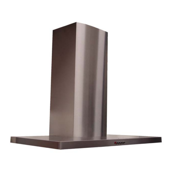
- Page 5 f- Conduit inférieur : Elargir légèrement les 2 bords latéraux (Fig.7, Rep. 7b) et les accrocher entre le conduit supérieur et la paroi; refermer jusqu'à la butée. fixer latéralement la partie inférieur au corps de la hotte à l'aide des 2 vis (12c) 2.9 x 9.5 fournies. FONCTIONNEMENT tableau de commande Touche...
- Page 6 • Débrancher complètement l’appareil. • Exigez toujours l’utilisation de pièces de rechange d’origine. La non observation de cette prescription peut compromettre la sécurité de l’appareil. • Lors de la commande de pièces détachées, rappeler le numéro de l’appareil inscrit sur la plaque signalétique située à...
- Page 14 Composants Componenti Components Componentes Bauelemente Onderdelen 7a 7a...
- Page 19 Halogen Beleuchtung Halogen Lighting Eclairage halogène Alogene Luci Alógenas Luz Halogeen Verlichting 2 x 40 W - 230 V...
- Page 21 Plaque Signalétique de la hotte Rating plate of the cookerhood Typenschild im Inneren der Dunstesse Etichetta all'interno della cappa Etiqueta de la campana Typeplaatje van de afzuigkap Modèle Model Numéro de série Modell Serial number Modello Seriennummer Modelo Numero di serie Model Numero de serie Serienummer...
- Page 22 Votre produit est conçu et fabriqué avec des matériaux et des composants de haute qualité, qui peuvent être recyclés et utilisés de nouveau. Lorsque ce symbole d’une poubelle à roue barrée est attaché à un produit, cela signifie que le produit est couvert par la Directive Européenne 2002/96/EC. Veuillez vous informer du système local de séparation des déchets électriques et électroniques.
- Page 24 93/68/EEG inzake de CE-markering. ROBLIN S.A. - Route de Caen - Sainte Cécile - B. P. 56 - 50800 VILLEDIEU-LES-POËLES - France Tél. 02 33 91 26 50 - Fax 02 33 51 54 79 - e-mail : com.France@roblin.fr For outside France : Tel.