
Manuels Connexes pour Fimer T 422


Sommaire des Matières pour Fimer T 422
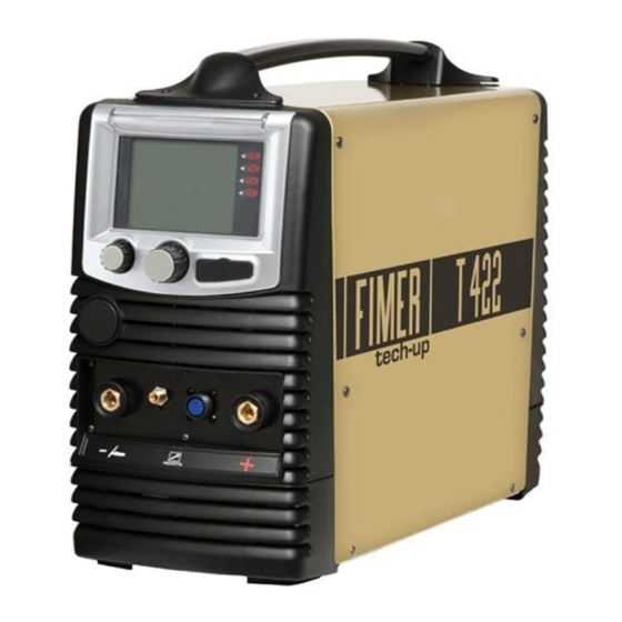
- Page 1 Manuale d’Istruzione Instruction Manual Manuel d’emploi Bedienungsanleitung Manual de instrucciones Cod. 910.100.397 REV04 T 422...
- Page 3 T 422...
- Page 4 TARGA DATI, NOMINAL DATA, LEISTUNGSCHILDER, PLAQUE DONÉES, PLACA DE CARACTERÌSTICAS...
-
Page 5: Table Des Matières
• AVVERTENZE ....................pag. 2, 3, 4 CARATTERISTICHE GENERALI E NOTE PER LA CONSULTAZIONE DEL MANUALE................... pag. 5 DESCRIZIONE DELL’APPARATO..............pag. 6 SALDATURA MMA..................pag. 7 3. 1 SALDATURA MMA Manuale................pag. 7 TABELLA DI SALDATURA ................pag. 8 COLLEGAMENTO PER SALDATURA MMA............ pag. -
Page 6: Avvertenze
Fimer S.p.A. Fimer SpA declina ogni responsabilità per danni a persone o cose derivanti da un uso inesperto, improprio o disattento del- INTRODUZIONE OGGETTI le proprie apparecchiature. - Page 7 INTERRUTTORE DI PROTEZIONE ACCESSORI Usare solo accessori previsti dal costruttore, l’uti- Verificare che l’impianto che alimenta la saldatrice sia lizzo di accessori di tipo differente può determina- dotato di opportuno organo di sezionamento e pro- re gravi malfunzionamenti dell’apparato. L’utilizzo di accessori non ori- tezione.
-
Page 8: Compatibilita' Elettromagnetica
SCARICHE ELETTRICHE PULIZIA DELL’AREA CIRCOSTANTE ALLA SCARICHE ELETTRICHE ZONA DI LAVORO Per ridurre il rischio di seri danni dovuti alle scariche elettriche, Ripulire accuratamente la zona di lavoro da qual- oltre alle avvertenze generali precedentemente riportate occor- siasi materiale combustibile. re rispettare scrupolosamente anche le seguenti precauzioni. -
Page 9: Caratteristiche Generali E Note Per La Consultazione Del Manuale
1. CARATTERISTICHE GENERALI E NOTE PER LA CONSULTAZIONE DEL MANUALE Le saldatrici tipo “T422” sono apparecchiature realizzate con tecnologia INVERTER; si tratta di apparati estremamente compatti e versatili utilizzabili in tutte le situazioni in cui, il minimo ingombro, si deve coniugare con le più elevate prestazioni. Queste saldatrici permettono di effettuare saldature in tecnologia MMA, TIG (lift). -
Page 10: Descrizione Dell'apparato
10). Valore evidenziato: Indica il parametro che viene variato tramite la manopola 10. VISUALIZZAZIONI: - All’accensione viene visualizzato il logo Fimer e la revisione Fig. 1 del Firmware caricata. PULSANTI DI COMANDO: (2, 3, 4, 5 di fig.1) Ad ogni pulsante di comando è... - Page 11 Seleziona il procedimento INIZIO Seleziona il procedimento MMA INIZIO Manuale INDIETRO OPZIONI OPZIONI Presa Frontale Presa Frontale PROCESSO DI SALDATURA 13 di Fig.1 11 di Fig.1 PINZA PORTA CAVO MASSA ELETTRODO...
-
Page 12: Saldatura Mma Manuale
4. TABELLA DI SALDATURA 6. INNESCO DELL’ARCO Attraverso la tabella riportata di seguito sarà ACCENSIONE possibile calcolare la corrente di saldatura a Creare il contatto per seconda dell’elettrodo utilizzato. accendere l’arco a circa 5 cm di distanza rispetto DIAMETRO CORRENTE DI LUNGHEZZA ELETTRODO SALDATURA... -
Page 13: Saldatura Tig
7. SALDATURA TIG Al fine di una migliore comprensione delle descrizioni dei parametri di saldatura ripor- tati, relativi alla modalità TIG, quando necessario fare riferimento agli andamenti riportati di seguito: Pulsante torcia TIG modalità 2t con rampe : corrente iniziale, tempo iniziale : corrente di saldatura : corrente di base : corrente finale, tempo finale... -
Page 14: Saldatura Tig (Lift-Arc)
Per scegliere questa modalità di saldatura : Durante la saldatura il potenziometro 8 di fig 1 regola la corrente di saldatura. tramite la manopola 10 scegliere TIG e La corretta connessione della torcia e del premere per conferma. cavo di massa è mostrata nella tabella sotto riportata: Seleziona il procedimento Presa Frontale... -
Page 15: Collegamento Per Saldatura Tig
rampa di salita: Permette di impostare la 2) Collegare la torcia all’apposito connettore “-” posto sul frontale (11 di fig 1). durata della rampa di salita della corrente di 3) L’inserimento deve avvenire allineando la saldatura. chiavetta con la scanalatura e stringendo pulsazione: Permette di attivare (Hz) o fino all’arresto tramite una rotazione in senso disattivare (OFF) la modalità... -
Page 16: Innesco Dell'arco Tig
9. INNESCO DELL’ARCO TIG 10.COLLEGAMENTO DELL’ALIMENTAZIONE Dopo aver aperto il gas, per mezzo dell’apposito Prima di collegare la macchina controllare rubinetto posto sull’impugnatura della torcia (A), tensione, numero di fasi e frequenza di alimentazione. regolarne la portata tramite il rubinetto (B) posto sulla bombola (intorno ai 6 litri/min) La tensione di alimentazione ammissibile è... - Page 17 Fig.7...
-
Page 18: Memorizzazione Del Punto Di Lavoro
15. MEMORIZZAZIONE DEL PUNTO DI 16. BLOCCO DEL PUNTO DI LAVORO LAVORO La saldatrice permette di bloccare le funzioni Come illustrato nei paragrafi precedenti la delle manopole 8 e 10 in modo che, fissato saldatrice permette notevole un punto di lavoro, esso non sia più personalizzazione del punto di lavoro (sia durante modificabile se non da personale in il funzionamento in manuale che in sinergico). - Page 19 Per potere utilizzare questo tipo di funzionalità di gestione del blocco della tastiera, funzione è necessario contattare Tasto F1 tramite la manopola 10 direttamente il servizio di assistenza (fig.1), indica il tasto da premere per attivare il tecnica FIMER. blocco.
- Page 20 è necessario con- riportato pop-up tattare direttamente il ser- richiede un inserimento vizio di assistenza tecnica dati da parte dell’utente FIMER. (es. inserimento nome programma, inserimento password di blocco/sbloc- Indica che il blocco co tastiera) tastiera è attivo Sostituisce il led lampeg-...
-
Page 21: Codice Errori
17. CODICE ERRORI Qui di seguito sono elencati gli errori che si possono incontrare e le relative descrizioni: Codice Descrizione 8101 Buffer dati non valido 8102 Errore durante la scrittura dati 8103 Indice/sottoindice CAN non valido 8104 Oggetto a sola lettura 8105 Errore durante la lettura dati 8106... -
Page 22: Ricerca Guasti
18. RICERCA GUASTI Qui di seguito sono elencati i più comuni problemi che si possono incontrare e le relative soluzioni. SOLUZIONI/CONSIGLI SEGNALAZIONE CAUSA/E Assenza di tensione sulla rete di ali- Ripristinare la tensione di Spegnimento della macchina [display: spento] mentazione alimentazione 1) Mancanza di una fase della rete 1) Controllare il collegamento alla... -
Page 23: Schema Blocchi
19.SCHEMA BLOCCHI 1. Interruttore generale 6. Trasformatore ausiliario 2. Filtro EMC 7. Convertitore di potenza 3. Scheda raddrizzatore circuiti di controllo 8. Induttanza 4. Controllo del processo di saldatura 9. Controllo ventilatore 5. Pannello di controllo 10. Presa di controllo remoto... -
Page 24: Parti Di Ricambio
20. PARTI DI RICAMBIO... - Page 25 USER AND MAINTENANCE MANUAL USER AND MAINTENANCE MANUAL Fimer S.p.A. would like to thank you for choosing this machine; if used according to the instructions reported in this user and maintenance manual, it will accompany you in your work for many years without any problems.
-
Page 26: Warning Symbols
WARNING SYMBOLS... -
Page 29: Caution
1. GENERAL SPECIFICATIONS AND NOTES FOR CONSULTING THIS MANUAL The “T 422” welders are made using INVERTER technology. They are extremely compact and versatile devices that can be used in all those situations that require minimum obstruction, combined with the highest performance. -
Page 30: Description Of The Equipment
Highlighted value: Indicates the welding parameter that is being changed with knob 10. VIEWS : Fig. 1 - At start-up, the Fimer logo and the Firmware revision are displayed. CONTROL BUTTONS: (2, 3, 4, 5 in fig.1) Each control button is associated with a specific function shown on the display. - Page 31 Select mode Seleziona il procedimento MMA START INIZIO Manuale INDIETRO OPZIONI OPTIONS Front Socket Front Socket WELDING PROCESS 13 of Fig.1 11 of Fig.1 ELECTRODE EARTH CABLE CLAMP HOLDER...
-
Page 32: Welding Table
4. WELDING TABLE 6. IGNITION OF THE MMA ARC Use the table below to calculate the IGNITION welding current, according to the type of electrode used: Create the contact for igniting the arc at a distance WORKPIECE WELDING ELECTRODE approximately 5 cm from THICKNESS CURRENT LENGTH... -
Page 33: Tig Welding
7. TIG WELDING In order for a better understanding of the descriptions of the welding parameters reported, related to the TIG mode, when necessary to make reference to the trends shown below: Torch Button 2t mode with ramps : start current, start time : welding current : background current : end current, end time... -
Page 34: Tig Welding (Lift-Arc)
To select this welding mode: The TIG procedure can be used on various types of metals, such as, ferrous materials, turn switch 10, select TIG and press alloys, nickel, copper, titanium, magnesium. confirm. Seleziona il procedimento During welding, potentiometer 8 in fig. 1, for example, regulates the welding current. -
Page 35: Adjustments And Settings
ADJUSTMENTS AND SETTINGS: 8. CONNECTOR FOR TIG WELDING 1) Connect the earth cable to the appropriate ‘+’ Button 8 controls the current and the socket on the front of the device (13 of Fig .1). machine power. Insert by lining-up the key with the groove and turn in a clockwise direction until it stops. -
Page 36: Ignition Of The Tig Arc
9. IGNITION OF THE TIG ARC 10. POWER CONNECTOR Before connecting the machine check the After opening the gas by means of the tap on tension, number of phases and the power the torch handle (A), adjust the flow rate using supply frequency. - Page 37 Fig.7...
-
Page 38: Memorising The Work Point
15. MEMORISING THE WORK POINT 16. LOCKING A WORK POINT The welder can lock the functions of As illustrated in the previous paragraphs, the switch 8 and 10, so that once a work point welder allows for a notable personalisation has been saved it cannot be changed, of the work point (when used both manually unless modified by a member of staff with... - Page 39 3. Once the password has been confirmed Appendix: titles/button symbols/function buttons the display will show the message in Fig. C, and pop-up notifications a lock symbol in the area 1 of the display and In the following figure and table, you will find the functions Unlock and Reset pw the descriptions of the principal title/button...
- Page 40 Position Position Symbol Description Symbol Description display display When the management F2 key This means the infor- function of the keyboard POP UP mation in the pop-mes- lock is activated, using sage is an error messa- switch 8 (fig.1), this indi- ge, which blocks cates the key to press for machine functions.
-
Page 41: Error Code
17. ERROR CODE Below lists the errors that you may encounter and their description: Codice Description 8101 Invalid data buffer 8102 Error while writing data 8103 Invalid CAN index/subindex 8104 Read-only CAN object 8105 Error while reading data 8106 Timeout expired while writing data 8107 Timeout expired while reading data 8108... -
Page 42: Troubleshooting
18. TROUBLESHOOTING Below are a list of some of the most common problems that may arise, with the relati- ve solutions. CAUSE/S SOLUTION/ADVICE INDICATION Lack of tension on the supply grid. Refresh the power supply Machine switches off tension. [display: off] Network error 1) Failure of one mains power supply phase 1) Check the connection to the... -
Page 43: Block Diagram
19. BLOCK DIAGRAM 1. Main switch 6. Auxiliary transformer 2. EMC filter 7. Power converter 3. Sheet rectifier control circuits 8. Inductance 4. Process control board 9. Fan control 5. Control panel 10. Remote control socket... -
Page 44: Spare Parts
20. SPARE PARTS... - Page 45 H A N D - U N D WA R T U N G S B U C H Fimer dankt Ihnen für den Erwerb dieses Gerätes. Es wird Sie für viele Jahre ohne Probleme bei Ihrer Arbeit begleiten, wenn Sie die folgenden Angaben und Hinweise im diesem Hand- und Wartungsbuch richtig befolgen.
-
Page 46: Verwendete Symbole
VERWENDETE SYMBOLE... -
Page 49: Allgemeine Eigenschaften Und Angaben Zur Einsicht Des Handbuchs
1. ALLGEMEINE EIGENSCHAFTEN UND ANGABEN ZUR EINSICHT DES HANDBUCHS Die Schweißgeräte des Typs „T422” sind Geräte, die mit der Technologie INVERTER hergestellt wurden. Es handelt sich um Geräte, die extrem kompakt und vielseitig sind, und in den Situationen perfekt einsetzbar sind, in denen ein Minimum an Platzaufwand und maximale Leistung benötigt werden. -
Page 50: Beschreibung Des Geräts
Angezeigter Wert: Gibt den Parameter an, der über den Abb. 1 Knopf 10 verändert werden kann. ANSICHTEN: - Beim Einschalten werden das Logo Fimer sowie eine Ansicht der Firmware angezeigt. BEDIENSCHALTER: (2, 3, 4, 5 der Abb. 1) Jedem Schalter wird eine spezielle Funktion zugewiesen, die auf dem Display angezeigt wird. - Page 51 Seleziona il procedimento Wahl MMA Verfahren INIZIO START Manuell ZURÜCK OPZIONI OPTIONEN Frontstecker Frontstecker SCHWEISSPRO- ZESS 13 Abb.1 11 Abb.1 ELEKTRODEN- MASSENKABEL STECKER...
-
Page 52: Schweisstabelle
4. SCHWEISSTABELLE 6. ERZEUGEN DES LICHTBOGENS BEI MMA Über die nachfolgende Tabelle können Sie die Schweissstromstärke je nach verwendeter EINSCHALTEN Elektrode berechnen. Erzeugen Sie den Kontakt zum Zünden des Bogens ELEKTRODEN- SCHWEISS- LÄNGE DER etwa DURCHMES- STROM- ELEKTRODE STÄRKE festgesetzten Beginn der Schweißnaht entfernt. -
Page 53: Wig Schweissen
7. WIG SCHWEISSEN Um zu einem besseren Verständnis der Beschreibung der Schweißparameter beri- chtet, bezogen auf das WIG, wenn notwendig, auf die Trends unten machen: Torch Knopf TIG 2t Modus mit Rampen : Anfangsstrom, Anfangszeit : Schweißstrom : Grundstrom : Ende Strom, Endzeit x100: Impuls Gleichgewicht : Pulsfrequenz : Nachgaszeit... -
Page 54: Wig Schweissen (Lift-Arc)
Während Schweißens regelt Zur Auswahl dieser Schweißtechnik: Potenzregler Abb. Über den Drehknopf 10 wählen Sie Schweißstromstärke. Verbindungsstromstärke WIG und drücken zur Bestätigung. Brennerkopfs und des Massenkabels wird in der nachfolgenden Tabelle angegeben. Verfahren wählen FRONTSTECKER FRONTSTECKER SCHWEISSPRO- START ZESS ELEKTRODE 13 Abb.1 11 Abb.1 MASSENKABEL BRENNERKABEL... -
Page 55: Anschluss Für Wig Schweissen
Stromanstiegszeit: 2) Verbinden Sie den Brennerkopf mit den Ermöglicht Halter auf der Vorderseite (11 der Abb.1). Einstellung der Dauer der Anstiegszeit des 3) Bei Einstecken muss der Stecker mit den Schweißstroms. Puls-Funktion: Ermöglicht die Einschaltung Einkerbungen ausgerichtet werden und über Drehen im Uhrzeigersinn festgezogen (Hz) oder... -
Page 56: Erzeugen Des Lichtbogens Bei Wig
9. ERZEUGEN DES LICHTBOGENS 10. NETZANSCHLÜSSE BEI WIG Vor dem Verbinden mit der Stromquelle Öffnen Sie den Gasaustritt über den Hahn auf dem kontrollieren Sie die Spannung, Phasenzahl Brennerkopf (A) und stellen Sie den Fluss über den und die Frequenz der Stromversorgung. Hahn (B) auf der Gasflasche auf etwa 6 Liter pro Minute ein. - Page 57 Abb.7...
-
Page 58: Speichern Des Schweisspunkts
15. SPEICHERN DES SCHWEISSPUNKTS 16. SPERREN DES SCHWEISSPUNKTES Wie in den vorherigen Abschnitten aufgezeigt Das Schweißgerät gestattet das Sperren von gestattet das Schweißgerät, den Schweißpunkt Funktionen der Knöpfe 8 und 10, so dass nach persönlich einzurichten (sowohl in manuell als der Speicherung eines Schweißpunkts dieser auch in synergisch). - Page 59 Entsperren erinnern. Wird über Knopf 10 (Abb. Zur Anwendung dieser Funktion ist es Funktion Tastatursperre aktiviert, Key F1 nötig, dass Sie direkt den technischen gibt sie an, welche Taste zur Sperrung zu drücken Kundendienst FIMER kontaktieren. ist.
- Page 60 Angabe der Firmware- nern. Zur Anwendung die- Versionen /SD im Gerät). ser Funktion ist es nötig, dass Sie direkt den tech- nischen Kundendienst FIMER kontaktieren. Die Pop-up Nachricht POP UP verlangt die Eingabe von Gibt dass Daten durch den Nutzer Tastatursperre eingeschal- (Z.B.
-
Page 61: Error Code
17. ERROR CODE Im Folgenden sind die Fehler, die auftreten können und ihre Beschreibungen: Code Beschreibung 8101 Ungültiger Pufferspeicher 8102 Fehler während der Dateneingabe 8103 Ungültiger CAN Index/Unterindex 8104 Objekt nur lesen 8105 Fehler während der Datenablese 8106 Zeitlimit wàhrend Dateneingabe erreicht 8107 Zeitlimit Datenablese erreicht 8108... -
Page 62: Fehlersuche
18. FEHLERSUCHE Nachfolgend werden die häufigsten Probleme aufgeführt, die sich ergeben können, sowie die dazugehörige Lösung. LÖSUNGEN/EMPFEHLUNGEN URSACHE/N ANZEICHEN Keine Netzspannung vorhanden Stellen Sie die Netzspannung Gerät schaltet sich aus wieder her [Display: ausgeschaltet] Netzwerkfehler 1) Ausfall einer Netzversorgung Phase 1) Überprüfen Sie den Anschluss an das Stromnetz und überprüfen Sie, ob die Sicherungen intakt sind. -
Page 63: Blockschaldbild
19.BLOCKSCHALDBILD 1. Wechseln 6. Hilfstransformer 2. EMC-Filter 7. Leistungsumwandler 3. Karte Gleichrichter-Schaltungen 8. Induktivität 4. Prozess-Kontrollkarte 9. Ventilatorbedienfeld 5. Kontrol-Panel 10. Fernbedienungsbuchse... -
Page 64: Ersatzteile
20. ERSATZTEILE... - Page 65 M A N U E L D’UTILISATION ET DE MAINTENANCE Fimer vous remercie d'avoir choisi cet appareil qui vous garantira de nombreuses années de fonctionnement sans problèmes à condition d’être utilisé en respectant les indications du manuel d’utilisation et de maintenance.
-
Page 66: Symboles Utilisés
SYMBOLES UTILISÉS... -
Page 69: Caractéristiques Générales Et Recommandations Pour La Consultation De Ce Manuel
1. CARACTÉRISTIQUES GÉNÉRALES ET RECOMMANDATIONS POUR LA CONSULTATION DE CE MANUEL Les postes à souder de type “T422” sont des appareils réalisés avec la technologie ONDULEUR. Il s'agit d'appareils extrêmement compacts et polyvalents, pouvant être utilisés dans toutes les situations où un encombrement minimum doit s'associer aux prestations les plus élevées. -
Page 70: Description De L'appareil
10. Fig. 1 VUES: - À l’allumage, le logo Fimer apparaît ainsi que le numéro de révision du Firmware. TOUCHES DE COMMANDE: (2, 3, 4, 5 di fig.1) Une fonction spécifique affichée sur l'afficheur est associée à... -
Page 71: Soudure Mma
étroites ou difficiles d’accès. Avec les postes à souder T 422 il est possible de souder tout type d'électrode et de diamètre. L'allumage de l’arc se produit en approchant l’électrode de la pièce à... -
Page 72: Tableau De Soudage
4. TABLEAU DE SOUDAGE 6. ALLUMAGE DE L'ARC À travers le tableau indiqué ci-après il sera possible ALLUMAGE de calculer le courant de soudage selon l'électrode utilisée. Créer le contact pour allumer l'arc à environ 5 DIAMÈTRES COURANT DE LONGUEUR DE distance SOUDAGE L'ÉLECTRODE... -
Page 73: Soudage Tig
7. SOUDAGE TIG Pour une meilleure compréhension de la description des paramètres de soudage rap- porté, lié à la mode TIG, lorsqu'il est nécessaire de faire référence aux tendances indiquées ci-dessous: BOUTON TORCH TIG 2T avec rampes : courant initial, temps initial : courant de soudage : courant de base : courant final, temps final... -
Page 74: Soudage Tig (Lift-Arc)
Pour choisir ce mode de soudage : Pendant le soudage, le potentiomètre 9 de la figure 1 règle le courant de soudage. Choisir TIG à l’aide du bouton rotatif 10 Le branchement correct de la torche et du et appuyer pour confirmer. câble de masse est indiqué... -
Page 75: Branchement Pour Le Soudage Tig
T de départ: Permet de sélectionner le 2) Brancher la torche au connecteur correspondant « - » placé sur la façade temps d'application du courant établi par le (11 de la fig 1). paramètre courant initial. 3) L’insertion se produit en alignant la clé Slope up: Permet de sélectionner la avec la cannelure et en resserrant le durée de la rampe de montée du courant... -
Page 76: L'allumage De L'arc Tig
9. L'ALLUMAGE DE L'ARC TIG 10. BRANCHEMENT DE L’ALIMENTATION Après avoir ouvert le gaz à l’aide du robinet Avant de brancher l’appareil, contrôler la prévu à cet effet placé sur la poignée de la tension, le nombre de phases et la fréquence torche (A), régler le débit avec le robinet (B) de l’alimentation. - Page 77 Fig.7...
-
Page 78: Mémorisation Du Point De Travail
15. MÉMORISATION DU POINT DE 16. BLOCAGE DU POINT DE TRAVAIL Le poste à souder permet de bloquer les TRAVAIL fonctions des boutons 8 et 10 de façon à ce Comme illustré dans paragraphes que, après avoir fixé un point de travail, il ne précédents, le poste à... - Page 79 Pour pouvoir utiliser ce type de clavier est activée par le Touche F1 biais du bouton 10 (figure fonction, il faut contacter directement 1), elle indique la touche service d'assistance technique à appuyer pour activer le blocage. FIMER.
- Page 80 POP UP indiqué dans le pop-up vice d'assistance techni- demande une saisie de que FIMER. la part de l'usager (par ex. saisie du nom du Indique que le blocage programme, saisie du mot de passe de bloca- du clavier est activé.
-
Page 81: Code D'erreur
17. CODE D'ERREUR Ci-dessous répertorie les erreurs que vous pouvez rencontrer et leur description: Code Description 8101 Buffer données non valide 8102 Erreur pendant l'écriture des données 8103 Index/sous-index non valable 8104 Sujet seulement en lecture 8105 Erreur pendant la lecture des données 8106 Timeout pendant l'écriture des données 8107... -
Page 82: Résolutions Des Problèmes
18. RÉSOLUTIONS DES PROBLÈMES Nous présentons ci-après les problèmes les plus communs qu’il est possible de rencontrer ainsi que les solutions correspondantes. SOLUTIONS/CONSEILS CAUSE/S SIGNALISATION Absence de courant sur le réseau d’a- Rétablir le courant Extinction du poste à souder limentation [afficheur : éteint] 1) Manque d'une phase du réseau. -
Page 83: Schéma Des Liaisons
19. SCHÉMA DES LIAISONS 1. Changer général 6. Transformateur auxiliaire 2. Filtre EMC 7. Convertisseur de puissance 3. Carte des circuits de commande de 8. Inductance redresseur 9. Commande du ventilateur 4. Contrôle du processus de soudage 5. Pupitre de contrôle 10. -
Page 84: Pièces De Rechange
20. PIÈCES DE RECHANGE... - Page 85 MANUAL DE USO Y MANTENIMIENTO MANUAL DE USO Y MANTENIMIENTO Fimer les agradece que hayan elegido este aparato; les acompañará en su trabajo por muchos años siéndoles de gran utilidad si lo utilizan siguiendo las indicaciones que aparecen en este manual de uso y mantenimiento.
- Page 86 SÌMBOLOS UTILIZADOS...
-
Page 89: Características Generales Y Notas Para Consultar El Manual
1. CARACTERÍSTICAS GENERALES Y NOTAS PARA CONSULTAR EL MANUAL Las soldadoras tipo “T422” son aparatos realizados con tecnología INVERTER; se trata de aparatos extremadamente compactos y versátiles que se pueden utilizar en todas las situaciones en las que, el menor estorbo, se tiene que conjugar con las mejores prestaciones. -
Page 90: Descripción Del Aparato
10. PUNTOS DE VISTA: Fig. 1 - Cuando se enciende, visualiza el logotipo Fimer y la revisión del Firmware. BOTONES DE MANDO: (2, 3, 4, 5 de la fig.1) A cada botón de mando se le asocia una función específica que se visualiza en el display. - Page 91 Seleccione el metodo COMIENZO Seleccione proceso MMA COMIENZO Manual VOLVER OPCIONES OPCIONES Toma Frontal Toma Frontal PROCESO DE SOLDADURA 13 de la Fig.1 11 de la Fig.1 PINZA PORTA- CABLE MASA ELECTRODOS...
-
Page 92: Tabla De Soldadura
4. TABLA DE SOLDADURA 6. CEBADO DEL ARCO MMA Con la ayuda de la tabla que se muestra a ENCENDIDO continuación se podrá calcular la corriente de soldadura según el electrodo utilizado. Crear el contacto para encender arco CORRIENTE aproximadamente 5 cm DIÁMETRO LONGITUD distancia... -
Page 93: Soldadura Tig
7. SOLDADURA TIG Con el fin de una mejor comprensión de las descripciones de los parámetros de sol- dadura se informó, relacionado con el modo TIG, cuando sea necesario para hacer referencia a las tendencias que se muestran a continuación: Antorcha interruptor soldadura 2t modo TIG con rampas : corriente inicial, tiempo inicial... -
Page 94: Soldadura Tig (Lift-Arc)
Para escoger esta modalidad de Durante la soldadura, el potenciómetro 9 de soldadura: la fig 1 regula la corriente de soldadura. con la ruedecilla 10 escoger TIG y En la tabla de abajo se muestra la correcta pulsar para confirmar. conexión de la antorcha y del cable de ma Seleccione el metodo Toma Frontal... -
Page 95: Conexión Para Soldadura Tig
2) Conectar la antorcha al debido T de départ: Permite configurar el tiempo durante el que se aplica la corriente estable- conector “-“ que se encuentra en la parte cida por el parámetro corriente inicial. frontal (11 de la Fig 1). Slope up: Permite configurar la duración de 3) La inserción se deberá... -
Page 96: Cebado Del Arco Tig
9. CEBADO DEL ARCO TIG 10. CONEXIÓN DE LA ALIMENTA- CIÓN Después de haber abierto el grifo del gas Antes de conectar la máquina controlar la que se encuentra sobre el mango de la antor- tensión, el número de fases y la cha de soldadura (A), regular el flujo a través frecuencia de la alimentación. - Page 97 Fig.7...
-
Page 98: Memorización Del Punto De Trabajo
15. MEMORIZACIÓN DEL PUNTO DE BLOQUEO PUNTO TRABAJO TRABAJO Como se ha ilustrado en los apartados anteriores, La soldadora permite bloquear las funciones de la soldadora permite una notable personalización las ruedecillas 8 y 10 de modo que, una vez que del punto de trabajo (ya sea durante el se haya fijado un punto de trabajo, este ya no funcionamiento en manual que en sinérgico). - Page 99 Tecla F1 Para poder utilizar este tipo de función, través de la ruedecilla 10 (fig.1), indica la tecla que hay que contactar directamente al hay que presionar para activar el bloqueo. servicio de asistencia técnica FIMER.
- Page 100 (ej. introducción stencia técnica FIMER. nombre programa, intro- ducción contraseña de Indica que el bloqueo b l o q u e o / d e s b l o q u e o teclado está...
-
Page 101: Código De Error
17. CÓDIGO DE ERROR A continuación se enumeran los errores que pueden surgir y sus descripciones: Código Descripción 8101 Buffer datos no valido 8102 Error durante la escritura de datos 8103 Indice/subindice CAN no valido 8104 Objecto de solo lectura 8105 Error durante la lectura de datos 8106... -
Page 102: Squeda De Averías
18. SQUEDA DE AVERÍAS A continuación se muestran los problemas más comunes que se pueden encontrar y las relativas soluciones. SOLUCIONES/ CAUSA/S SEÑALIZACIÓN RECOMENDACIONES La ausencia de tensión en la red de Restaurar el poder suministrar Apagado de la máquina [display: apagado] suministro de energía 1) falta de una fase de la red... -
Page 103: Diagrama De Bloques
19. DIAGRAMA DE BLOQUES 1. Cambiar general 6. Transformador auxiliar 2. Filtro EMC 7. Convertidor de potencia 3. Tarjeta de rectificadores 8. Inductancia circuitos de control 9. Control del ventilador 4. Control proceso 5. Panel de control 10. Toma el control remoto... -
Page 104: Piezas De Repuesto
20. PIEZAS DE REPUESTO... - Page 105 NOTE: ................................................................................................................................................................................
- Page 106 NOTE: ................................................................................................................................................................................