R&G LP0183BK Mode D'emploi
Les langues disponibles
Les langues disponibles
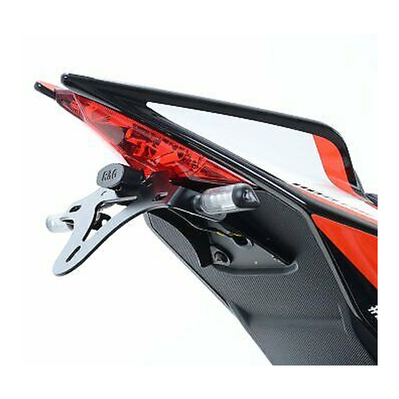
FITTING INSTRUCTIONS FOR LP0183BK LICENCE PLATE BRACKET
THIS KIT CONTAINS THE ITEMS PICTURED AND LABELLED BELOW.
DO NOT PROCEED UNTIL YOU ARE SURE ALL PARTS ARE PRESENT.
Please note that the way the kit is packed does not necessarily represent the way of mounting to the bike.
T
HE PARTS SHOWN MAY BE REPRESENTATIVE ONLY
3
4
6 6
Unit 1, Shelley's Lane, East Worldham, Alton, Hampshire, GU34 3AQ
Tel: +44 (0)1420 89007 Fax: +44 (0)1420 87301
APRILIA RSV4 & TUONO '15-
1
5
R&G Racing
www.rg-racing.com
(
FOR CLARITY OF INSTRUCTIONS ONLY
2
3
3
4
10
Email:
info@rg-racing.com
).
7
8
9
10
Table des Matières

Manuels Connexes pour R&G LP0183BK


Sommaire des Matières pour R&G LP0183BK
- Page 8 INSTRUCTIONS DE MONTAGE POUR LP0183BK SUPPORT DE PLAQUE APRILIA RSV4 & TUONO ’15- Assurez vous que toutes les pièces soient présentes avant de procéder au montage. La façon dont le kit est emballé ne correspond pas forcément à la façon de monter les pièces sur la moto.
-
Page 9: Outils Requis
LEGENDE ARTICLE 1 = SUPPORT PRINCIPAL (TB0183 Part 1) (x1). ARTICLE 2 = BOUCHON DE CAOUTCHOUC (RB0002) (x1). ARTICLE 3 = M6 x 6mm BOULONS (x4). ARTICLE 4 = ADAPTATEURS DE CLIGNOTANTS (I0041) (x2). ARTICLE 5 = SUPPORT DE PLAQUE AJUSTABLE (TB0183 Part 2) (x1). ARTICLE 6 = LA0002 No. - Page 10 Photo 3 Photo 4 Photo 5 Photo 6 Photo 7 Photo 8 R&G Racing Unit 1, Shelley’s Lane, East Worldham, Alton, Hampshire, GU34 3AQ Tel: +44 (0)1420 89007 Fax: +44 (0)1420 87301 www.rg-racing.com Email: info@rg-racing.com...
- Page 11 Photo 9 Photo 10 Photo 11 Photo 12 Photo 13 Photo 14 R&G Racing Unit 1, Shelley’s Lane, East Worldham, Alton, Hampshire, GU34 3AQ Tel: +44 (0)1420 89007 Fax: +44 (0)1420 87301 www.rg-racing.com Email: info@rg-racing.com...
- Page 12 Photo 15 Photo 16 Photo 17 Photo 18 INSTRUCTIONS DE MONTAGE Pour monter le support R&G, enlever le siège passager ou la bosse arrière à l’aide de la clé. Soulever le bloc électrique monté sur le caoutchouc pour permettre l’accès au bloc de connecteur blanc pour les clignotants arrière &...
- Page 13 Une fois le support de plaque d’origine extrait de la moto, enlever le boulon qui fixe le feu de plaque en place, voir photo 9. A présent, vous avez accès aux 2 boulons qui sont fixés dans le passage de roue. Enlever ces boulons, voir photo 10.
- Page 14 Prendre le clignotant adéquat pour ce coté de la moto, puis placer la griffe de fixation, avant de l’enrouler en position. Remonter l’écrou d’origine ainsi que le boulon, avant de serrer. Faire cela pour les 2 clignotants. Passer les fils dans le trou de fixation, dans le corps de clignotant adéquat, comme enlevé et remonté...